Page is loading ...

TUBE-O-THERM® Low Temperature Gas Burners
www.maxoncorp.com
combustion systems for industry
Maxon reserves the right to alter specifications and data without prior notice.
© 2012 Copyright Maxon Corporation. All rights reserved.
1-2.1-1
E- i -8/21
TUBE-O-THERM®
Low Temperature Gas Burners
Fires directly into small-bore immersion tubes
Burner-to-tube direct firing system allows uniform heat transfer, eliminates “hot spots”, and
produces faster bring-up times
Economical and efficient package design with integral low power blower costs less and saves
energy (external blower models also available)
No hassle installation and easy maintenance access with wall mounted design
Burns natural, propane or butane gas and produces reduced levels of NOx and CO
Flame scanner capability for all sizes
Four models sized for 3”, 4”, 6”, 8” and 10” diameter tubes
Heat releases up to 8,500,000 Btu/hr
No powered exhaust required, saving energy

www.maxoncorp.com
combustion systems for industry
Maxon reserves the right to alter specifications and data without prior notice.
© 2012 Copyright Maxon Corporation. All rights reserved.
1-2.1-2
E- i -8/21
TUBE-O-THERM® Low Temperature Gas Burners
Product description
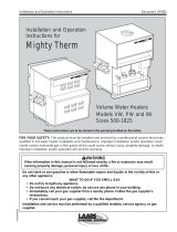
MAXON TUBE-O-THERM® burners are nozzle-mixing, gas fired, refractory-less burners specifically designed for firing into a small
bore tube. The burner fires cleanly with natural gas, propane, butane or LPG blends.
TUBE-O-THERM® burners are available in two basic versions:
packaged with integral combustion air blower
EB (external blower) for use with an external combustion air source for extended capacities
Both versions incorporate a gas and air valve linked together to control the gas/air ratio over the full throttling range of the burner.
Gas flows through the gas nozzle where it mixes with the combustion air.
1) Fire tube
2) Tank wall
3) Air inlet
4) Air control valve
5) Air mixing plate
6) Gas nozzle
7) Gas control valve
8) Gas inlet
1
2
5
7
8
6
4
3

TUBE-O-THERM® Low Temperature Gas Burners
www.maxoncorp.com
combustion systems for industry
Maxon reserves the right to alter specifications and data without prior notice.
© 2012 Copyright Maxon Corporation. All rights reserved.
1-2.1-3
E- i -8/21
Available TUBE-O-THERM® burner sizes
Typical burner data
Fuel: natural gas at 60°F with 1000 Btu/ft3 (st) HHV - sg = 0.6 [1]
Combustion air: 60°F - 21% O2 - 50% humidity - sg = 1.0 [1]
Stated pressures are indicative. Actual pressures are a function of air humidity, altitude, type of fuel and gas quality.
TUBE-O-THERM® burner Size 3” 4” 6”
Description Pkgd. EB Pkgd. EB Pkgd. EB
Maximum capacity MBtu/h 0.5 0.75 0.9 1.35 2.0 3.0
Pilot capacity MBtu/h 0.05 0.075 0.09 0.135 0.13 0.2
Minimum capacity MBtu/h 0.05 0.075 0.09 0.135 0.16 0.24
Gas pressure burner inlet “wc 35.3 72.5 29.5 65.3 36.5 76.4
Gas pressure burner test port “wc 32.1 63.0 25.8 56.9 29.2 62.1
Combustion air pressure required “wc 5.6 16.8 6.6 15.4 8.4 17.1
[1] sg (specific gravity) = relative density to air (density air = 0.0763 lb/ft3 (st) )
Typical burner data
Fuel: natural gas at 60°F with 1000 Btu/ft3 (st) HHV - sg = 0.6 [1]
Combustion air: 60°F - 21% O2 - 50% humidity - sg = 1.0 [1]
Stated pressures are indicative. Actual pressures are a function of air humidity, altitude, type of fuel and gas quality.
TUBE-O-THERM® burner
Size 8” burner
Description Pkgd. EB 8” HC
8” tube [2]
8” HC
10” tube [2]
Maximum capacity MBtu/h 3.5 5.3 7.5 8.5
Pilot capacity MBtu/h 0.35 0.53 0.50 0.50
Minimum capacity MBtu/h 0.35 0.47 0.25 0.28
Gas pressure burner inlet “wc 37.0 76.0 125 144
Gas pressure burner test port “wc 33.0 72.0 110.8 139
Combustion air pressure required “wc 9.9 24.9 29.7 27.1
[1] sg (specific gravity) = relative density to air (density air = 0.0763 lb/ft3 (st) )
[2] HC burners require the use of an external blower (EB)

www.maxoncorp.com
combustion systems for industry
Maxon reserves the right to alter specifications and data without prior notice.
© 2012 Copyright Maxon Corporation. All rights reserved.
1-2.1-4
E- i -8/21
TUBE-O-THERM® Low Temperature Gas Burners
Applications
Typical applications include industrial solution heating jobs such as dip tanks, glycol reboilers, spray washers, pickling or quench
tanks and salt baths. TUBE-O-THERM® burners may also be used with proper design for indirect air heaters and bakery ovens.
1) TUBE-O-THERM®
burner
2) Combustion air fan
3) Air/gas control linkage
4) MAXON gas pipe train
1
2
3
4

TUBE-O-THERM® Low Temperature Gas Burners
www.maxoncorp.com
combustion systems for industry
Maxon reserves the right to alter specifications and data without prior notice.
© 2012 Copyright Maxon Corporation. All rights reserved.
1-2.1-5
E- i -8/21
Dimensions and weights
Packaged TUBE-O-THERM® burners
1) Gas test connection
2) Gas inlet
3) Required dimension for
ignitor removal
4) Combustion air blower
Dimensions in inches unless stated otherwise
Burner size A B C D E F [1] Weight lbs
3” 21.6 15.8 18.8 10.5 4.9 1/2” 145
4” 22.7 17.5 20.34 10.5 5.7 1/2” 170
6” 28.55 20.5 23.03 15.0 7.75 3/4” 265
8” 30.7 23.75 25.5 14.0 9.2 1-1/4” 370
[1] Connections are threaded (NPT or ISO)
A
1
2
D
3
4
E
B
C
F

www.maxoncorp.com
combustion systems for industry
Maxon reserves the right to alter specifications and data without prior notice.
© 2012 Copyright Maxon Corporation. All rights reserved.
1-2.1-6
E- i -8/21
TUBE-O-THERM® Low Temperature Gas Burners
EB (external blower) TUBE-O-THERM® burners
Typical emissions
TUBE-O-THERM® burners utilize rapid mixing of fuel and air to suppress formation of NOx. With lower levels of excess air than
many tube burners, the TUBE-O-THERM® also controls the production of CO to low levels at most of its firing rates.
Exact emissions performance may vary in your application. Contact MAXON for information on installation specific estimates or
guarantees. No guarantee of emissions is intended or implied without specific written guarantee from MAXON.
Read “Specifications of TUBE-O-THERM® burners” for correct and complete information on TUBE-O-THERM® burners.
1) Gas test connection
2) Gas inlet
3) Required dimension for
ignitor removal
4) Combustion air inlet
Dimensions in inches unless stated otherwise
Burner size A B C D E F [1] GWeight lbs
3” EB 6.75 15.75 18.72 10.5 4.9 1/2” 4.0 105
4” EB 7.50 17.5 20.34 10.5 5.7 1/2” 4.0 135
6” EB 9.4 20.49 23.03 15.0 7.75 3/4” 6.0 200
8” EB 11.6 23.75 25.5 14.0 9.2 1-1/4” 6.0 295
[1] Connections are threaded (NPT or ISO)
A
G4
C
F
B
1
2
3
D
E
/