Page is loading ...

002-998e-09.21
Kistler Group, Eulachstrasse 22, 8408 Winterthur, Switzerland, Tel. +41 52 224 11 11 www.kistler.com
Kistler Group products are protected by various intellectual property rights. For more details, visit www.kistler.com
TheKistler Group includes Kistler Holding AG and all its subsidiaries in Europe, Asia, the Americas and Australia.
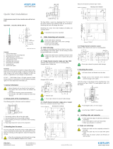
Mounting set for preparation of the clamping surface
for strain sensors Type 9232A, 9234B, 9237B and 9238B
Preparation/Bill of materials
For the preparation of clamping surfaces, which meet the mini-
mum requirements (see sensor manual), a tool set Type 9431B
including a drill jig material number 55231551 is available on re-
quest.
Quantity Parts list assembly tool set Type 9431B
1 Drill jig 105x40x30 with holding magnet
1 Twist drill ø5
1 Tap set M6 3 pieces DC N1110-S
1 Counterbore ø14
1 Special countersink ø45
1 Roller pin ø12/M6x28
1 Drill bush ø5
1 Drill bush ø6.3
1 Drill bush ø14
In addition to the included parts, the following tools are required:
• Slow-speed hand drill with 13 mm drill chuck and switchable
speed, continuously adjustable, power at least 600 watts. The
use of a magnetic stand drill enables better compliance with
the perpendicularity tolerance.
• Tap wrench for M6 taps
• Cutting oil
• 1 screwdriver No. 5
• Grease-dissolving cleaning agent
• Cleaning cloths or paper

002-998e-09.21
Kistler Group, Eulachstrasse 22, 8408 Winterthur, Switzerland, Tel. +41 52 224 11 11 www.kistler.com
Kistler Group products are protected by various intellectual property rights. For more details, visit www.kistler.com
TheKistler Group includes Kistler Holding AG and all its subsidiaries in Europe, Asia, the Americas and Australia.
1.1 Remove casting skin with hand grinder.
1.2 Position the drill jig, if possible in the direction of the
highest expected tilting moment when drilling.
Insert drill bush ø5 mm, material number 55230608.
1.3 Drill with twist drill ø5 mm, material number 65007751.
Speed 1200 1/min.
1.4 Insert drill sleeve ø14 mm, material number 52230611,
into drill jig material number 55231551.
Counterbore with flat countersink material number
65007752.
Speed 430 1/min.
Use cutting oil. Avoid chatter marks. Do not cant the tool,
otherwise the drill jig may be displaced.
Process description

002-998e-09.21
Kistler Group, Eulachstrasse 22, 8408 Winterthur, Switzerland, Tel. +41 52 224 11 11 www.kistler.com
Kistler Group products are protected by various intellectual property rights. For more details, visit www.kistler.com
TheKistler Group includes Kistler Holding AG and all its subsidiaries in Europe, Asia, the Americas and Australia.
1.5 Insert drill sleeve ø6.3 mm, material number 52230609,
into drill jig material number 55231551.
Cut M6 thread using tap set material number 55238714.
Use cutting oil.
Remove the drill jig.
1.6 Screw roller pin ø12 mm/M6 x28, material number
55236390, into M6 thread. Ensure that the ø14 mm
chamfer is clean. Tighten slightly with screwdriver.
Lubricate bearing journal well with cutting oil.
1.7 Counterbore surfaces with special countersink ø45 mm
material, number 55233298, until surface is clean in the
contact area of the strain sensor.
Maximum speed 180 1/min. Use cutting oil.
The ø45 mm surface must not be countersunk by more
than 0.8 mm!
Do not cant the special countersink to the bearing journal!
Avoid chatter marks.
Remove roller pin ø12mm/M6 x28, material number
55236390
/
