Quantum Q-Logic 3e Controller Owner's manual
- Type
- Owner's manual


Copyright © 2020
INFMANU5154/Rev A/May 2020
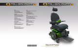
IDENTIFICATION KEY
USB-C Charger Port
Page Button
Mode Button
Horn Button
XLR Charger Port XLR Charger Port
Joystick
Power Button
Soft Keys
LCD Screen
On/Off Mode Jacks

3
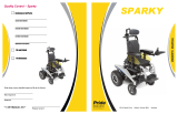
Attendant Control
IDENTIFICATION KEY
Mode Button
Mode LED
Actuator Indicators
Battery Condition Meter
On/Off Button
Joystick
On/Off and Mode Jacks

4BASIC OPERATION INSTRUCTIONS
WARNING!
A Quantum Rehab Provider or a qualified technician
must perform the initial setup of this product and must
perform all of the instructions in this manual.
The symbols below are used throughout this owner’s manual
and on the power chair to identify warnings and important
information. It is very important for you to read them and
understand them completely.
Indicates a potentially hazardous condition/situation.
Failure to follow designated procedures can cause either
personal injury, component damage, or malfunction. On
the product, this icon is represented as a black symbol
on a yellow triangle with a black border.
These actions should be performed as specified. Failure
to perform mandatory actions can cause personal injury
and/or equipment damage. On the product, this icon is
represented as a white symbol on a blue dot with a white
border.
These actions are prohibited. These actions should
not be performed at any time or in any circumstances.
Performing a prohibited action can cause personal
injury and/or equipment damage. On the product, this
icon is represented as a black symbol with a red circle
and a red slash.
Intended Use
A wheelchair component is a device intended for
medical purposes that is generally sold as an integral
part of a wheelchair, but may also be sold separately as
a replacement part.
Regarding Devices for Prescription Use
CAUTION! Federal law restricts this device to sale by or
on the order of a physician or other certified personnel
licensed by the law of the State (US only) or region in
which this personnel practices to use or order the use
of the device.
WARNING!
MANDATORY!
PROHIBITED!
Safety Guidelines NOTE: These instructions are compiled from the latest
specifications and product information available at
the time of publication. We reserve the right to make
changes as they become necessary. Any changes to
our products may cause slight variations between the
illustrations and explanations in this manual and the
product you have purchased. The latest/current version
of this manual is available on our website.
NOTE: This product is compliant with WEEE, RoHS, and
REACH directives and requirements.
NOTE: This product meets IPX4 classification (IEC
60529).
NOTE: The Q-Logic 3e Controller and its components
are not made with natural rubber latex. Consult with the
manufacturer regarding any after-market accessories.
WARNING!

5
Product Safety Symbols ......................................... 5
The Q-Logic 3e Controller ......................................6
Precautionary Guidelines ....................................... 6
Operating the Q-Logic 3e Controller .....................6
On/Off Button ............................................................. 6
Joystick ...................................................................... 6
Lock/Unlock Procedure ............................................. 6
Speed Adjustment ..................................................... 6
Keypad ....................................................................... 7
Horn Button ............................................................... 7
Mode Button .............................................................. 7
Page Button ............................................................... 7
Soft Keys ................................................................... 7
Light Soft Keys ........................................................... 7
Left/Right Turn Indicator Soft Keys ............................ 7
LCD Screen ............................................................... 8
Drive Profile Selection ............................................... 9
Actuator Adjustment (Seat Screen) ........................... 9
iLevel® Feature (Optional) ....................................... 10
Settings Screen ....................................................... 12
USB Charging .......................................................... 13
Bluetooth Functions ................................................. 13
Interactive Assist ..................................................... 13
Attendant Control ..................................................14
Thermal Rollback ...................................................14
Battery Condition Meter ........................................ 14
Battery Life Indicator ............................................. 15
Q-Logic 3e Error Codes ........................................15
Care and Maintenance .......................................... 16
Temperature ........................................................... 16
Warranty ................................................................. 16
Graphic User Interface Icons ................................ 17
BASIC OPERATION INSTRUCTIONS
Product Safety Symbols
The symbols below are used on the controller to identify
warnings, mandatory actions, and prohibited actions. It
is very important for you to read and understand them
completely.
Table of Contents
Read and follow the instructions in
the owner's manual.
Avoid exposure to rain, snow, ice,
salt, or standing water whenever
possible. Maintain and store in a
clean and dry condition.
EMI/RFI - This product has been
tested and passed at an immunity
level of 20 V/m.
Disposal and recycling - Contact
your Quantum Rehab Provider for
information on proper disposal and
recycling of your Quantum product
and its packaging.

6
The Q-Logic 3e Controller
The Q-Logic 3e Controller is a fully programmable, modular
electronic controller system that allows you to operate your
power chair. The hand control will primarily be discussed in
this manual along with references to the Attendant Control.
Contact your Quantum Rehab Provider for more information.
The controller has been pre-programmed to meet a typical
user's needs. The program is adjusted using either a
personal computer with software provided by the controller
manufacturer or with a handheld programmer, also provided
by the controller manufacturer, by your Quantum Rehab
Provider or a trained service technician.
The controller program can affect speed acceleration,
deceleration, dynamic stability, and braking. If it is
programmed incorrectly or outside of the safe limits
as determined by your healthcare professional, it can
create a dangerous situation. Only your Quantum Rehab
Provider or a trained technician should program your
controller.
Precautionary Guidelines
Before operating the Q-Logic 3e Controller please read the
following. These guidelines are provided for your benefit and
will aid you in the safe operation of the seating system.
Turn off the power to the controller before you are seated
in your power chair.
Always have assistance when you are being seated in
your power chair.
Follow all of the procedures and heed the warnings
as explained in your power chair owner’s manual and
Consumer Safety Guide.
Operating the Q-Logic 3e Controller
The Q-Logic 3e hand control is used to operate your power
chair and all of its components.
On/Off Button
The On/Off button turns the system on and off. It also resets
the controller if the LCD screen shows a prompt of a finger
pressing the power button when programming has been
updated
When faced with an emergency situation, release the
joystick, then press the on/off to stop the power chair.
Use caution. Be advised that pressing the on/off button
may cause the power chair to stop abruptly.
Always turn the power off when you are stationary to
prevent unexpected movement.
WARNING!
WARNING!
Joystick
The joystick controls the driving speed and direction of the
power chair and is used to navigate the menus on the LCD
screen. When the joystick is at rest, it is in the neutral (center)
position and the chair is stationary. In order to drive the chair,
the joystick must be taken out of neutral. Moving the joystick
in any direction will switch the chair from neutral to drive,
and the chair will move in the direction indicated by the
joystick position. The farther away from the neutral position
the joystick is, the faster the chair will move in that direction.
To stop chair movement, simply release the joystick or move
it back to the neutral position. The chair’s electromagnetic
brakes will engage after the chair has come to a controlled
stop.
Lock/Unlock Procedure
The Q-Logic 3e Controller comes with a programmable lock/
unlock option.
NOTE: The lock-out feature is not programmed at
the factory. To have this feature added, contact your
Quantum Rehab Provider.
To lock the controller:
1. Push the On/Off Button once to power on the chair and
the controller.
2. Push and hold the Mode Button until the controller
turns off. The controller is now locked.
To unlock the controller:
1. Push the On/Off Button once to power on the chair
and the controller. The “System Lock Icon” will appear
on the display screen.
2. Move the joystick to the full forward position until you
hear a beep.
NOTE: This will take several seconds.
3. Move the joystick to the full reverse position until you
hear a beep.
NOTE: This will take several seconds.
4. Release the joystick. The controller is now unlocked.
Speed Adjustment
The speed adjustment is used to control the speed of the
power chair.
To change the speed:
1. Push the On/Off Button once to power on the chair and
the controller.
2. To increase your speed, press the speed up soft key.
3. To decrease your speed, press speed down soft key.
The speed indicator arc will increase and decrease as the
speed arc keys are pressed, providing a visual display of
how fast the chair will move.
BASIC OPERATION INSTRUCTIONS

7
1 2
3
Keypad
The keypad is located directly in front of the joystick. It
contains the components that you will use to control your
power chair.
Horn Button
The horn button activates a warning horn.
Mode Button
The mode button is used to cycle through Drive Profiles,
Seat Mode (if equipped) and Settings Mode.
Page Button
The page button is used to cycle through the soft key pages.
NOTE: The soft key pages can be changed by your Quantum
Rehab Provider.
Soft Keys
The soft keys will perform the action depicted directly above
them. This action may change depending on the screen and
it will change with the page button.
NOTE: If your Q-Logic 3e Controller is equipped with
a lighting system, the soft key buttons will default to a
light and left/right turn indicator.
Light Soft Key
The light soft key controls the front headlights and rear
running lights.
To operate the lights:
1. Push the On/Off Button once to power on the chair and
the controller.
2. Press the light soft keys button once to activate the front
headlights and rear running lights.
3. Press the light soft key button again to turn off the
lighting system.
NOTE: On the Drive Screens a light icon will be displayed
above the speed arc when the headlights are on.
Left/Right Turn Indicator Soft Keys
The left/right turn indicator soft keys toggle either the left or
right turn indicators.
To operate the turn indicators:
1. Push the On/Off Button once to power on the chair and
the controller.
2. Press the desired turn indicator soft key once to turn on
that indicator.
3. Press the same turn indicator soft key again to turn off
that indicator.
NOTE: If the left turn indicator is activated, pressing the
right indicator soft key will turn off the left indicator and
activate the right indicator.
NOTE: On the Drive Screens a Left/Right turn indicator
icon will be displayed next to the speed arc when the
Left/Right turn indicator is on.
NOTE: The turn indicator soft keys also control the
hazard lights. Press both turn indicator soft keys at the
same time to activate the hazard lights and press both
buttons again to turn off the hazard lights. If the hazard
lights are left on and the controller is turned off, the
hazard lights will continue to flash. The Q-Logic 3e must
be turned back on and both turn indicator buttons must
be pressed to deactivate the hazard lights.
Drive Mode Setting Mode
Seating Mode
BASIC OPERATION INSTRUCTIONS

8
Drive Screen
The LCD screen, provides the current profile, drive operation,
and the speed adjustment settings.
Drive/Function Inhibit status is depicted as an icon at the top
left of the screen. Actuator adjustment will affect the inhibit
status. As your seat and/or back angle increases, a red icon
will indicate full drive lockout. If your power chair is equipped
with a seating system lift, a yellow icon will indicate speed
reduction as the seat is elevated. To return your power chair
to full speed, reverse operation.
To Access the Drive Screen from the Home Screen
1. Push the joystick up for the "Drive Screen."
NOTE: To access the Drive Screen from any other screen,
press the Mode Button until the desired Drive Profile
is reached.
BASIC OPERATION INSTRUCTIONS
LCD Screen
The Q-Logic 3e provides the user with easily intuited
feedback information via the LCD screen. The top left corner
of the screen will indicate any drive restrictions.
No icon Full drive speed
Yellow Caution Icon Limited Drive Speed
Red Warning Icon Full Drive Lockout
1 2
34
5 6
7
Inhibit Status Indicator Battery Indicator
Percentage of Full Speed of
Drive Indicator Left Soft Key Indicator
Middle Soft Key Indicator Right Soft Key Indicator
Drive Indicator
Outdoor Graphic User Interface
The Q-Logic 3e includes an outdoor Graphic User Interface
that increases the contrast of the screen to make it easier to
be seen in natural light.
To switch from the indoor to outdoor Graphic User Interface
or from the outdoor to indoor Graphic User Interface, press
and hold page button until the screen changes.

9
Drive Profile Selection
Your Q-Logic 3e Controller may be programmed for up to
four drive profiles that allow the system to be custom-tailored
to your environment. Profiles 1 – 3 may be selected by
pressing the Mode button. The selected profile is displayed
on the Drive Screen.
NOTE: Drive profiles are set by your Quantum Rehab
Provider. Contact your Quantum Rehab Provider to
change or add a drive profile.
To select a profile setting using the Mode Button:
1. Push the On/Off Button once to power on the chair and
the controller.
2. Push the Mode Button to select a drive profile. Cycle
through the four available drive profiles.
3. Continuing to push the button will cycle through the
Setting screen and Seat screen (if power positioning is
present), then back to Drive profile 1.
Drive/Function Inhibit status is read-only in your
actuator adjustment (seat screen). This function is
disabled in drive mode in order to prevent unintended
loss of function in your power chair. Take caution when
negotiating, obstacles, ramps, and inclines. Whenever
possible, use an attendant in these conditions.
Operating your power chair on inclines and/or with tilt/
recline function will affect your power chair's stability.
Actuator Adjustment (Seat Screen)
The Q-Logic 3e Controller can control five power seat
actuators, using the mode button and the joystick.
To select and adjust an actuator:
1. Push the On/Off Button once to power on the chair and
the controller.
2. Push the Mode Button several times until the seat
screen is displayed on the LCD or push the middle soft
key button once to go directly to actuator mode.
3. Push the joystick to the left or right to cycle through
the available actuators until the desired actuators are
illuminated on the actuator indicator. See figure 1.
4. When the desired actuator is selected, give a forward
command to the joystick to adjust position in one
direction or give a reverse command to the joystick to
adjust position in the opposite direction. If you continue
to push the Mode Button, it will cycle through the Drive
screens and Auxiliary screen, and then return to Seat
Screen.
5. Push the Mode Button until you return to the desired
drive profile.
WARNING!
NOTE: The Drive/Function Inhibit status is affected only
in the actuator adjustment (seat screen).
Recline & ELR/ ALR Mode
(both)
Elevating Seat Mode
Figure 1. Actuator Selection
BASIC OPERATION INSTRUCTIONS
Tilt Mode
Recline Mode
Articulating Foot Platform

10
The iLevel feature should be used only on a flat, level,
indoor surface, such as in malls, offices, and/or medical
facilities. Never raise the seat from its lowest position
on an inclined surface. Failure to heed this warning can
result in the power chair tipping over.
The iLevel feature is intended for limited outdoor use on
only flat level, hardscape surfaces. If you are unsure of
your environment, do not use iLevel outdoors.
Never raise the seat into iLevel when operating your
power chair on bumpy or uneven surfaces. Failure to
heed this warning can result in the power chair tipping
over.
Always fasten the positioning belt when operating the
power chair.
Do not operate the iLevel or change the seat height in
any way while your power chair is positioned under a
fixed object, such as a table or a desk. Keep area clear
prior to and during movement.
To activate the iLevel using a single switch:
1. Press once and hold the single switch once to raise the
seat and activate iLevel.
2. Press and hold the single switch to lower the seat.
NOTE: The iLevel feature is automatically engaged when
the power elevating seat is activated and the iLevel
indicator is displayed on your controller. See figure 2.
WARNING!
NOTE: The iLevel feature is equipped with a system that
allows the power chair to drive at a predetermined, safe
speed when the seat is elevated. Always check to be
sure this system is operating properly before using your
power chair.
NOTE: If a warning or visual indicator appears on your
controller stating that iLevel is not engaged, the power
chair’s speed will be reduced to 25% when elevated.
If this warning appears while on level ground, please
discontinue use of iLevel feature and consult your
Quantum Rehab Provider for assistance.
iLevel Feature (Optional)
Your power chair may be equipped with the iLevel feature
that will be used in conjunction with your seating system.
The iLevel feature is mounted on a Quantum power base
for enhanced stability when the seating system is elevated.
There are certain situations, including some medical
conditions, where the power chair user will need to practice
operating the power chair equipped with iLevel in the
presence of a trained attendant. A trained attendant can be
defined as a family member or care professional specially
trained in assisting a power chair user in various daily living
activities.
As you begin using iLevel during daily activities, you will
probably encounter situations in which you will need some
practice. Simply take your time and you will soon be in full
and confident control.
Elevation (Seat Screen)
The iLevel feature can be activated by selecting the elevating
seat actuator.
To select and adjust the seat elevation using the Q-Logic 3e
Controller:
1. Push the On/Off Button once to power on the chair and
the controller.
2. Push the Mode Button several times until the seat
screen is displayed on the LCD or push the middle soft
key button once to go directly to seat screen. See figure 1.
3. Push the joystick to the left or right to cycle through to the
elevating seat mode, this is illuminated on the actuator
indicator.
NOTE: If your Q-Logic 3e settings are different than
those described, contact your Quantum Rehab Provider.
Your Quantum Rehab Provider may have changed the
programming of your Q-Logic 3e Controller.
4. When the elevating seat mode is selected, give a
forward command to the joystick to adjust position in one
direction or give a reverse command to the joystick to
adjust position in the opposite direction.
5. If you want to return to another profile, push the Mode
Button to return to the desired drive profile.
The power chair should be used on an indoor, level surface,
such as malls, offices, and/or medical facilities to activate
iLevel. Once the seating system actuator is started, the
iLevel boots inhibit movement on the front caster arms. The
seating system can be reclined or tilted up to 20° while the
iLevel feature is activated.
Never use the iLevel outdoors on uneven terrain (gravel,
hills or other uneven, non-compact terrain) or in fields.
Never use iLevel while ascending or descending a curb
or uneven surface of any height.
PROHIBITED!
BASIC OPERATION INSTRUCTIONS

11
Figure 2. Q-Logic 3e Controller Indicators
1a 1b
1c
Definitions of Indicators
1a - Safe Elevation
1b - Reduced speed restriction
1c - Full drive lockout
Safe Elevation Reduced speed
restriction
Full drive lockout
BASIC OPERATION INSTRUCTIONS
iLevel not engaged

12
Settings Screens
The following pages explain the various screens you will use
with the Q-Logic 3e Controller. Contact your Quantum Rehab
Provider with any questions you may have.
NOTE: Some screens in this Basic Operating Instructions
may differ from your system depending on configuration
and options selected.
To change the horn volume:
1. Push the Mode button, until setting screen is displayed.
2. Push the joystick up to enter the available setting
subjects. Push left or right to change the settings.
3. When the desired subject is displayed on the screen,
push the joystick up or down to adjust that setting.
After "Horn" is displayed, an up command will increase
volume, a down command will decrease volume.
NOTE: Any time a setting is changed, the system will
back up the configuration to the power base. When the
system is turned off, "parameter backup" will be
displayed on the screen before the system turns off.
To change the display brightness:
1. Push the Mode button, until setting screen is displayed.
2. Push the joystick up to enter the available setting
subjects. Push left or right to change settings subject.
3. When the desired subject is displayed on the screen,
push the joystick up or down to adjust that subject.
After "Display Brightness" is displayed, an up command will
increase brightness and a down command will decrease
brightness.
Drive Screen Settings
Sound Brightness
To change the horn volume: To change the display setting:
1. 2.
3. 3.
BASIC OPERATION INSTRUCTIONS
Drive Screen Settings
1. 2.

13
NOTE: This product has been tested for Electromagnetic
and Radio Frequency Interference (EMI/RFI) and has met
standard requirements. Please refer to the Consumer
Safety Guide for more information regarding EMI/RFI.
Although we do not recommend using a cell phone
while operating a power chair, the system is capable
of receiving and/or making calls through a cell phone
device, accessing music files or contact lists, and
navigating a device menu.
Bluetooth Electronic Specifications
EMC Testing on Sample Wheelchair
Bluetooth Output Power 10 mW
Operation Range 40 m LOS (Line of Sight)
Operating Temperature -40°F to 185°F / -40°C
to 85°C
Storage Temperature -67°F to 302°F / -55°C
to 150°C
RF Wireless Technology Type Co-existence with IEEE
802.11 (AWMA, AFH)
Encryption Security 128-bit
Susceptibility Tested to 20V/m to IEC 61000-4-3
Emissions To CISPR11, Group 1, Class B
ESD To IEC 610000-4-2
FCC ID
FCC ID: T7V1316
IC: 216Q-1316
FCC Information contains transmitter module
The Q-Logic 3e system includes Bluetooth that can be
used to program the Q-Logic 3e electronics.
If a programmer is connected to the power chair, the Q-Logic
3e screen will ask the user to accept Bluetooth access by
programming device.
1. To accept the Bluetooth connection, perform a forward
command on the power chair's input device.
To accept Bluetooth access by programming device:
BASIC OPERATION INSTRUCTIONS
Interactive Assist
The Interactive Assist uses the Q-Logic 3e's Bluetooth
connection to allow your provider access to the Q-Logic 3e's
Diagnostic information. The connection requires the user to
accept access similar to the Bluetooth programming. Refer
to the Interactive Assist manual for details.
USB Charging Port
The Q-Logic 3e hand control includes a USB-C port for
charging small devices.
The USB port will output up to 1.5 Amps depending on the
adaptor.

14
Attendant Control
For more information on this applications, contact your
Quantum Rehab Provider.
The Attendant Control is laid out:
On/Off Button
Enables/disables power
Mode Button
Cycle through Drive Profiles and Seat Mode (if equipped)
Battery Condition Meter
Indicates battery charge
Actuator LEDs
Indicates actuators in use
Mode LED
Used for profile selection
Joystick
They joystick controls speed and direction in Drive mode.
Push the joystick to the right to select actuators in Seat
mode. Move the joystick forward or backward to activate
the desired actuator(s).
On/Off and Mode Jacks
Allow for remote On/Off and Mode switch installations
BASIC OPERATION INSTRUCTIONS
Thermal Rollback
The Q-Logic 3e Controller is equipped with a thermal rollback
circuit that monitors the temperature of the power chair's
motors and controller. If either exceeds the safe operating
temperature, the controller reduces the output to 20% of full
operation level. This reduces the power chair's speed and
allows a cool-down period. Once the temperature returns to
a safe level, the power chair will resume normal operation.
Battery Condition Meter
The battery condition meter is in front of the joystick on the
controller and as an LED on the Attendant Control.
Or
GREEN: ~100%–50%
YELLOW: ~49%–25%
RED: ~24%–0%
BATTERY CONDITION METER
Figure 3. Battery Condition Meter

15
BASIC OPERATION INSTRUCTIONS
Battery Life Indicator
The Q-Logic 3e Controller system uses pop-ups to indicate
the remaining battery life of the power chair. The system
will show information screens when the battery voltage
is at 50%, 30%, and 15%. If the pop-ups are not needed,
this feature can be disabled, using a programmer, such as
Econ-W or Econ-I, under the display settings.
Battery Charge 50% Battery Charge 30%
Battery Charge 15%
Q-Logic 3e Error Codes
The Q-Logic 3e Controller displays two types of messages:
warning and error. See figure 4.
Warning: Alerts you to conditions that may affect power
chair functionality and performance.
Error: Alerts you to conditions that influence power chair
functionality and performance.
Error codes are displayed on the LCD by number. The
following table identifies the error codes that may be easily
rectified, probably causes, and possible solutions. If you
receive one of these error codes, follow the recommended
solution, and if the problem persists, you receive any other
error code or experience any other problem with your power
chair, contact your Quantum Rehab Provider.
INFORMATION
WARNING
ERROR
Figure 4. Error Codes

16 BASIC OPERATION INSTRUCTIONS
Care and Maintenance
Refer to your power chair owner's manual for proper cleaning
and disposal instructions.
Temperature
Some of the parts of your power chair are susceptible to
extreme changes in temperature. Always keep your power
chair between the temperatures of 18°F (-8°C) and 122°F
(50°C).
Warranty
Refer to your power chair owner's manual for specific
information on controller warranty.

17
Item Icon Name Icon visual Comments
X4 Power
Cycle
Shown when power cycle is required. Indicates a required action/input.
X5 DB backup Shows when system is backing up any changes made.
X6 DB restore Shows when system is restoring parameters from Power base.
X7 Animated bar;
Animated
element
Shows when system is processing internally.
X8 Firmware
update
Shown if system has detected an update and asks to confirm the installation upon a
forward input command. Similarity to BT connection x. Icon Select on top, "Update"
text on the bottom. Indicates a required action/input.
X9 Home drive A forward command will move to the first drive profile.
X10 Home seat A right command will move to the seat screen.
X11 Home settings A left command will move to the settings screen.
X12 Battery
outline;
Battery X,
Battery
charging
The battery state shall have the following state indications:
1. Green, 100% segments (total, full)
2. Green, 80% segment
3. Green, 60% segment
4. Yellow, 40% segment
5. Red, 20% segment
6. Red Cross (empty)
Percentage is shown below. While charging, an indication shall be added in front of
it.
X13 BT visible Shows when Bluetooth is enabled.
X14 BT connected Shows when Bluetooth is connected.
X15 Configuring
network
Item that indicates that the system modules are being configured. Shows animated
bar below.
Graphic User Interface - General System
BASIC OPERATION INSTRUCTIONS

18
Item Icon Name Icon visual Comments
D1.1 Drive 1 to 4 Shown while in drive profile. 4 profiles. Example: D1.
D1.2 Drive Indoor
slow; Drive indoor
moderate; Drive
outdoor fast; Drive
school; Drive work;
Drive ramp; Drive
sport
Icon to represent drive profile as opposed to Dx, must be programmed
by the dealer. Outdoor fast icon shown.
D1.3 Drive green circle;
Drive purple
pentagon; Drive
white square; Drive
red triangle; Drive
blue cross; Drive
yellow star
Icon to represent drive profile as opposed to Dx, must be programmed
by dealer. Yellow star symbol shown.
D2 Drive 5 - 100 Shows reachable profile speed with speed adjust setting. 19 items.
Example. 60%.
D4 iLevel Shown if iLevel drive mode is active while seat is elevated. Shown in
drive and seat screens.
D5 Drive restricted Shown if a drive speed restriction of any source is active. Shown in
drive and seat screens.
D6 Drive Inhibited Shown if driving is inhibited. Shown in drive and seat screens.
D7 Attendant Drive
1/2
The attendant drive has 2 profiles.
GUI Icons - Drive
Item Icon Name Comments
L1 Light on Icon shows while light status "on". No icon shows if light status
"off."
L2 Indicator left on Icon shows while left indicator "on". Shall alternate on and off. No
icon shows if left indicator "off."
L3 Indicator right on Icon shows while right indicator "on". Will alternate on and off. No
icon shows if right indicator "off."
L4 Hazzard on Icons show while hazard status "on". Will alternate on and off. No
icons show if hazard "off." Use indicator icons.
Lights, Indicators, Hazard
BASIC OPERATION INSTRUCTIONS

19
BASIC OPERATION INSTRUCTIONS
Seat
Seat Icons
Item Icon Name Icon Visual Comments
S1 Main Seat Tilt
Forward
Seating and seatback icon, both highlighted. Direction arrows,
forward highlighted.
S2 Main Seat Tilt
Backward
Seating and seatback icon, both highlighted. Direction arrows,
backward highlighted.
S3 Main Seat
Recline
Forward
Seatback icon highlighted. Direction arrows, forward highlighted.
S4 Main Seat
Recline
Backward
Seatback icon highlighted. Direction arrows, backward highlighted.
S5 Main Seat
elevate up
Seating highlighted. Direction arrows, up highlighted.
S6 Main Seat
elevate down
Seating highlighted. Direction arrows, down highlighted.
S7 Main Seat
AFP, Legs out
Used, if both legs operate at the same time:
-AFP
-Legs
-Left leg & right leg combined
Foot platform, consisting of 2 elements (1 rear, 1 feet), both
highlighted. Arrows, forward highlighted.
S8 Main Seat,
AFP, Legs in
Used, if both legs operate at the same time:
-AFP
-Legs
-Left leg & right leg combined
Foot platform, consisting of 2 elements (1 rear, 1 feet), both
highlighted. Arrows, forward highlighted.
S9 Main Seat
Legs up
Consisting of 2 elements (1 rear, 1 feet) feet highlighted. Left side
chair view. Arrows, reverse highlighted (same placement as 4.1)
S10 Main Seat
Legs down
Consisting of 2 elements (1 rear, 1 feet) feet highlighted. Left side
chair view. Arrows, reverse highlighted (same placement as 4.2)
Seatback
Seating
Rear (legs)
Feet (legs)

20
Item Icon Name Icon Visual Comments
S11 N/A Seat right leg up. Seat left leg up remains in place
S12 N/A Seat right leg down. Seat left leg remains in place..
Item Icon Name Icon Visual Comments
M2 Settings Settings menu icon, selected with forward input. Left or right input
lead to Bluetooth or information menu icon. Shown as well: Select/
Next/Previous
M3 Select Select menu item. Highlighted if activated by input device forward
input.
M4 Previous Navigates through menu and settings items. Highlighted if activated
by input devices right input (all).
M5 Next Navigates through menu and settings items. Highlighted if activated
by input device right input (all).
M6 Change plus Highlighted if activated by input device forward input.
M7 Change
minus
Highlighted if activated by input device reverse input.
M8 Brightness Large brightness change icon. Shown as well: Next/Previous/
Change plus/minus
M9 Beep Large beep volume change icon. Shown as well: Next/Previous/
Change plus/minus
M10 Horn Large horn volume change icon. Shown as well; Next/Previous/
Change Plus/minus.
M11 BT Main
Menu
Main Bluetooth, press up to enable.
Auxillary Functions
BASIC OPERATION INSTRUCTIONS
Seat Icons continuted
Page is loading ...
Page is loading ...
Page is loading ...
Page is loading ...
Page is loading ...
Page is loading ...
Page is loading ...
Page is loading ...
-
 1
1
-
 2
2
-
 3
3
-
 4
4
-
 5
5
-
 6
6
-
 7
7
-
 8
8
-
 9
9
-
 10
10
-
 11
11
-
 12
12
-
 13
13
-
 14
14
-
 15
15
-
 16
16
-
 17
17
-
 18
18
-
 19
19
-
 20
20
-
 21
21
-
 22
22
-
 23
23
-
 24
24
-
 25
25
-
 26
26
-
 27
27
-
 28
28


Quantum Q-Logic 3e Controller Owner's manual
- Type
- Owner's manual
Ask a question and I''ll find the answer in the document
Finding information in a document is now easier with AI
Related papers
-
Quantum Q-Logic 3 Controller Owner's manual
-
-
-
-
-
-
-
-
-
Other documents
-
 Pride Mobility Tru-Balance 3 Power Positioning Systems Owner's manual
-
 Pride Mobility Quantum Rehab Catalog Owner's manual
-
 Pride Mobility 1121 User manual
-
 Quantum Rehab Power Chairs 600 Owner's manual
-
Pride Quantum Rehab edge Owner's manual
-
 Quantum Rehab 6000 XL Owner's manual
-
-
 Pride Mobility Quantum Q6 Edge HD Owner's manual
-
-
 Pride Mobility Quantum 6000Z 3S User manual


