Page is loading ...

1
0£
Instruction Manual
HI 8510 • HI 8512
HI 8710 • HI 8711
HI 8720
Panel Mounted
pH and ORP
Indicators and Controllers
SLOPE
DOSAGE
OXID. REDUC.
ΔAL
COARSE
SET
FINE
ΔAL
MEA
SURE SET
0 mV
TEST 500 mV
TEST
HI 8720E
ORP
mV
www.hannainst.com

3
2£
2
PRELIMINARY EXAMINATION
Remove the instrument from the packing
material and examine it carefully to make
sure that no damage has occurred during
shipping. If there is any noticeable damage,
immediately notify your dealer.
Each model is supplied complete with
transparent splash-proof front cover, mounting
brackets and instruction manual
Note: Save all packing materials until you
are sure that the instrument functions
correctly. All defective items must be
returned in the original packing materials
together with the supplied accessories.
GENERAL DESCRIPTION
HI 8510 and HI8512 pH and ORP panel-
mounted indicators, and HI 8710, HI 8711
and HI 8720 pH and ORP controllers, are
ideal for process control monitoring in a wide
range of industrial applications.
These instruments have been designed for
easy and fast installation, and are provided
with membrane keypads on the front panel,
large display and autodiagnostic functions.
All connections are made through screw ter-
minals on the rear panel.
Two versions are available for each model, to
accept either a direct input from a pH or ORP
electrode (E version) or from a transmitter
through 4-20mA input (T version).
Moreover, you can choose the output
configuration for connecting a recorder or a
PLC, between 0-20 or 4-20 mA.
Dear Customer,
Thank you for choosing a HANNA instruments®
product.
Please read this instruction manual carefully
before using the instrument.
If you need additional technical information,
do not hesitate to e-mail us at
These instruments are in compliance with the
directives.
Preliminary Examination ............................. 3
General Description..................................... 3
Available Models ......................................... 4
Mechanical Dimensions .............................. 6
Functional Description HI 8510.................... 7
Functional Description HI 8512.................. 10
Functional Description HI 8710.................. 13
Functional Description HI 8711 .................. 16
Functional Description HI 8720.................. 20
Specifications............................................ 24
Initial Preparation ...................................... 27
Operational Guide ..................................... 30
pH Calibration ........................................... 34
pH Values at Various Temperature............. 36
pH Diagnostic Tests .................................. 37
ORP Diagnostic Tests............................... 39
LED Indication........................................... 40
Taking Redox Measurements .................... 41
Electrode Maintenance.............................. 43
Suggested Installations ............................. 47
Accessories.............................................. 49
Warranty ................................................... 55
TABLE OF CONTENTS

5
4£
4
AVAILABLE MODELS
HI 8510E020 pH indicator with electrode
input and 0-20 mA recorder
output
HI 8510E420 pH indicator with electrode
input and 4-20 mA recorder
output
HI 8510T020 pH indicator with input from
transmitter and 0-20 mA
recorder output
HI 8510T420 pH indicator with input from
transmitter and 4-20 mA
recorder output
HI 8512E020 ORP indicator with electrode
input and 0-20 mA recorder
output
HI 8512E420 ORP indicator with electrode
input and 4-20 mA recorder
output
HI 8512T020 ORP indicator with input from
transmitter and 0-20 mA
recorder output
HI 8512T420 ORP indicator with input from
transmitter and 4-20 mA
recorder output
HI 8710E020 pH controller with electrode
input and 0-20 mA recorder
output
HI 8710E420 pH controller with electrode
input and 4-20 mA recorder
output
HI 8710T020 pH controller with input from
transmitter and 0-20 mA
recorder output
HI 8710T420 pH controller with input from
transmitter and 4-20 mA
recorder output
HI 8711E020 pH controller with 2 setpoints,
electrode input and 0-20 mA
recorder output
HI 8711E420 pH controller with 2 setpoints,
electrode input and 4-20 mA
recorder output
HI 8711T020 pH controller with 2 setpoints,
input from transmitter and 0-
20 mA recorder output
HI 8711T420 pH controller with 2 setpoints,
input from transmitter and 4-
20 mA recorder output
HI 8720E020 ORP controller with electrode
input and 0-20 mA recorder
output
HI 8720E420 ORP controller with electrode
input and 4-20 mA recorder
output
HI 8720T020 ORP controller with input from
transmitter and 0-20 mA
recorder output
HI 8720T420 ORP controller with input from
transmitter and 4-20 mA
recorder output

7
6£
6
FUNCTIONAL DESCRIPTION HI 8510
FRONT PANEL
SLOPE
Δ
SENSOR
TEST
pH 7
TEST pH 4
TEST
pH
HI 8510E
pH
Keypad
SENSOR TEST
To display the mV reading of the electrode and,
therefore, verify its working condition
pH 7 TEST
To verify the internal circuit of the meter in terms
of Offset compensation
pH 4 TEST
To verify the amplifier circuit of the meter
Trimmers
ΔΔ
ΔΔ
ΔOFor Offset calibration
SLOPE For Slope calibration
MECHANICAL DIMENSIONS
The meters are provided with a black anodized
aluminum body, front and back panels in
shockproof ABS plastic and a transparent
splash-proof front cover.
Front view of the panel-mounted unit
The dimensions show the cutout size for the
installation.
Side view of the panel-mounted unit
Adjustable location brackets (supplied with
the meter) allow the indicator to slide into the
cutout and will hold the unit securely in place.
190 mm (7.50") is the minimum space re-
quired to install the indicator with complete
wiring.
190mm MIN
7.50"
135mm
5.31"
0.25/4mm
0.01/0.160"
1
44mm
5.67"
ADJUSTABLE
LOCATION
BRACKET
141mm
5.55" 144m
m
5.67
"
69mm
2.71"
72mm
2.83"

9
8£
8
1. Fuse holder
2. Power supply terminals
3. Recorder output terminals
4. Connections to the transmitter
REAR PANEL HI 8510T
1. Fuse holder
2. Power supply terminals
3. Recorder output terminals
4. Connections for Pt100 temperature sensor
5. BNC socket for pH electrode
FUSE
FUSE
ELECTRODE
INPUT
PT100
mA OUT
+
-
220
110
L
1
2
3
4
5
REAR PANEL HI 8510E
Unplug the instrument from the power
supply before replacing the fuse. Unplug the instrument from the power
supply before replacing the fuse.

11
10£
10
1. Fuse holder
2. Power supply terminals
3. Recorder output terminals
4. BNC socket for ORP electrode
REAR PANEL HI 8512E
FUSE
FUSE
ELECTRODE
INPUT
220
110
L
1
2
3
4
mA OUT
+
-
FUNCTIONAL DESCRIPTION HI 8512
Keypad
0 mV TEST To verify the instrument cali-
bration at 0 mV
500 mV TEST To verify the slope at 500 mV
Trimmers
SLOPE For slope calibration
FRONT PANEL
SLOPE
0 mV
TEST 500 mV
TEST
mV
HI 8512E
ORP
Unplug the instrument from the power
supply before replacing the fuse.

13
12£
12
FUNCTIONAL DESCRIPTION HI 8710
Keypad
SET To set the pH dosage limit
MEASURE To enter measurement mode
and to enable diagnostic tests
SENSOR TEST To display electrode mV reading
and verify its working condition
ΔΔ
ΔΔ
ΔAL To display & set alarm tolerance
pH 7 TEST To verify Offset compensation
pH 4 TEST To verify amplifier circuit
Trimmers
ΔΔ
ΔΔ
ΔOFor Offset calibration
SLOPE For Slope calibration
ΔΔ
ΔΔ
ΔAL To set the alarm tolerance
SET/COARSE To coarsely adjust the setpoint
SET/FINE To finely adjust the setpoint
LEDs
ACID Show that acid dosage is active
BASE Show that basic dosage is active
ΔΔ
ΔΔ
ΔAL (blinking) Indicate an active alarm
FRONT PANEL
SLOPE
ACID BASE
ΔAL
0
Δ
COARSE
SET
FINE
SENSOR
TEST
MEA
SURE
ΔAL
SET
pH 7
TEST pH 4
TEST
pH
HI 8710E
pH
1. Fuse holder
2. Power supply terminals
3. Recorder output terminals
4. Connections to the transmitter
REAR PANEL HI 8512T
Unplug the instrument from the power
supply before replacing the fuse.

15
14£
14
1. Fuse holder
2. Power supply terminals
3. Acid/Basic dosage selection terminals
4. Red/ox dosage consent terminals
5. Connections for dosing pump
6. Alarm contacts
7. Recorder output contacts
8. Connections to the transmitter
REAR PANEL HI 8710T
1. Fuse holder
2. Power supply terminals
3. Acid/Basic dosage selection terminals
4. Red/ox dosage consent terminals
5. Connections for dosing pump
6. Alarm contacts
7. Recorder output contacts
8. Connections for Pt100 temperature sensor
9. BNC socket for pH electrode
REAR PANEL HI 8710E
FUSE
FUSE
ELECTRODE
INPUT
PT100
mA OUT
OPEN: ACID
SHORT: BASE
+
-
SET
CONSENT
ALARM
220
110
L
1
2
3
7
8
9
4
6
5
Unplug the instrument from the power
supply before replacing the fuse. Unplug the instrument from the power
supply before replacing the fuse.

17
16£
16
ΔΔ
ΔΔ
ΔAl To display and set the
alarm tolerance
pH 7 TEST To verify Offset compen-
sation
pH 4 TEST To verify amplifier circuit
Trimmers
ΔΔ
ΔΔ
ΔOFor Offset calibration
SLOPE For Slope calibration
ΔΔ
ΔΔ
ΔAL To set the tolerance of the
alarm
ACID SET/COARSE To coarsely adjust
acid setpoint
ACID SET/FINE To finely adjust acid
setpoint
BASE SET/COARSE To coarsely adjust
basic setpoint
BASE SET/FINE To finely adjust basic
setpoint
LEDs
ACID SET (Blinking) Show that acid dos-
age is active
BASE SET (Blinking) Show that basic
dosage is active
ΔΔ
ΔΔ
ΔAL (Blinking) Indicate active alarm
FUNCTIONAL DESCRIPTION HI 8711
Keypad
ACID SET To set the working point
of acid dosage
BASE SET To set the working point
of basic dosage
MEASURE To enter measurement
mode and to enable
diagnostic tests
SENSOR TEST To display electrode mV
reading and, therefore,
verify its working condition
FRONT PANEL
SLOPE
ΔAL
Δ
COARSE
ACID SET
FINE
COARSE
FINE
BASE SET
HI 8711E
SENSOR
TEST
MEA
SURE
ACID
SET
ΔAL
BASE
SET
pH 7
TEST pH 4
TEST
pH
HI 8711E
pH

19
18£
18
1. Fuse holder
2. Power supply terminals
3. Connections for dosing pump for acid
4. Connections for dosing pump for base
5. Alarm contacts
6. Recorder output contacts
7. Connections to the transmitter
REAR PANEL HI 8711T
1. Fuse holder
2. Power supply terminals
3. Connections for dosing pump for acid
4. Connections for dosing pump for base
5. Alarm contacts
6. Recorder output contacts
7. Connections for Pt100 temperature sensor
8. BNC socket for pH electrode
REAR PANEL HI 8711E
FUSE
FUSE
ELECTRODE
INPUT
PT100
mA OUT
+
-
BASE
ACID
ALARM
220
110
L
1
2
6
7
8
3
5
4
Unplug the instrument from the power
supply before replacing the fuse. Unplug the instrument from the power
supply before replacing the fuse.

21
20£
20
Trimmers
SLOPE For Slope calibration
ΔΔ
ΔΔ
ΔAL To display and set the alarm
tolerance
SET/COARSE To coarsely adjust the
setpoint
SET/FINE To finely adjust the setpoint
LEDs
OXID Show that the oxidant dosage is
active
REDUC Show that the reductant dosage
is active
ΔΔ
ΔΔ
ΔAL (blinking) Indicate an active alarm
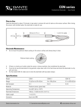
FUNCTIONAL DESCRIPTION HI 8720
Keypad
SET To set the working point of ORP
dosage
MEASURE To enter measurement mode and
to enable diagnostic tests
ΔΔ
ΔΔ
ΔAl To display and set the alarm
tolerance
0 mV TEST To verify the instrument
calibration at 0 mV
500 mV TEST To verify the slope at
500mV
FRONT PANEL
SLOPEDOSAGE
OXID. REDUC.
ΔAL
COARSE
SET
FINE
ΔAL
MEA
SURE SET
0 mV
TEST 500 mV
TEST
mV
HI 8720E
ORP

23
22£
22
1. Fuse holder
2. Power supply terminals
3. Ox/Red dosage selection terminals
4. Ox/red dosage consent terminals
5. Connections for dosing pump
6. Alarm contacts
7. Recorder output contacts
8. Connections to the transmitter
REAR PANEL HI 8720T
1. Fuse holder
2. Power supply terminals
3. Ox/Red dosage selection terminals
4. Ox/red dosage consent terminals
5. Connections for dosing pump
6. Alarm contacts
7. Recorder output contacts
8. BNC socket for ORP electrode
REAR PANEL HI 8720E
FUSE
FUSE
ELECTRODE
INPUT
CONSENT
mA OUT
OPEN: OXD
SHORT: RDX
+
-
SET
ALARM
220
110
L
1
2
3
7
4
8
6
5
Unplug the instrument from the power
supply before replacing the fuse. Unplug the instrument from the power
supply before replacing the fuse.

25
24£
24
HI 8510E HI 8510T
Range 0.00 to 14.00 pH
Resolution 0.01 pH
Accuracy ±0.02 pH ±0.5%
Typical EMC Dev. ±0.1 pH / ±0.2 mA
Installation Category II
Input 1012 Ohm 4 to 20 mA
Calibration Offset: ±2 pH with Δ0 trimmer
Slope: 80 to 110% with slope trimmer
Temperature Fixed or automatic with Pt100
Compensation from 0 to 100°C (32 to 212°F)
Recorder Output 0-20 mA or 4-20 mA (isolated)
Power Supply 115 or 230 Vac; 50/60 Hz
Environment -10 to 50°C (14 to 122°F);
RH max 95% non condensing
Panel Cutout 141 x 69 mm (5.6 x 2.7'')
Weight 1 kg (2.2 lb.)
SPECIFICATIONS HI 8710E HI 8710T
Range 0.00 to 14.00 pH
Resolution 0.01 pH
Accuracy ±0.02 pH ±0.5%
Typical EMC Dev. ±0.1 pH / ±0.2 mA
Installation Category II
Input 1012 Ohm 4 to 20 mA
Calibration Offset: ±2 pH with Δ0 trimmer
Slope: 80 to 110% with slope trimmer
Temperature Fixed or automatic with Pt100
Compensation from 0 to 100°C (32 to 212°F)
Relays 1 for setpoint and 1 for alarm,
max 2A, 240 V resistive load (isolated)
Recorder Output 0-20 mA or 4-20 mA (isolated)
Power Supply 115 or 230 Vac; 50/60 Hz
Environment -10 to 50°C (14 to 122°F);
RH max 95% non condensing
Panel Cutout 141 x 69 mm (5.6 x 2.7'')
Weight 1 kg (2.2 lb.)
HI 8512E HI 8512T
Range ±1000 mV
Resolution 1 mV
Accuracy ±5 mV ±0.5%
Typical EMC Dev. ±6 mV / ±0.2 mA
Installation Category II
Input 1012 Ohm 4 to 20 mA
Calibration Slope: 90 to 110% with slope trimmer
Recorder Output 0-20 mA or 4-20 mA (isolated)
Power Supply 115 or 230 Vac; 50/60 Hz
Environment -10 to 50°C (14 to 122°F);
RH max 95% non condensing
Panel Cutout 141 x 69 mm (5.6 x 2.7'')
Weight 1 kg (2.2 lb.)
HI 8711E HI 8711T
Range 0.00 to 14.00 pH
Resolution 0.01 pH
Accuracy ±0.02 pH ±0.5%
Typical EMC Dev. ±0.1 pH / ±0.2 mA
Installation Category II
Input 1012 Ohm 4 to 20 mA
Calibration Offset: ±2 pH with Δ0 trimmer
Slope: 80 to 110% with slope trimmer
Temperature Fixed or automatic with Pt100
Compensation from 0 to 100°C (32 to 212°F)
Relays 2 for setpoint and 1 for alarm,
max 2A, 240 V resistive load (isolated)
Recorder Output 0-20 mA or 4-20 mA (isolated)
Power Supply 115 or 230 Vac; 50/60 Hz
Environment -10 to 50°C (14 to 122°F);
RH max 95% non condensing
Panel Cutout 141 x 69 mm (5.6 x 2.7'')
Weight 1 kg (2.2 lb.)

27
26£
26
•Connect a 3-wire cable to
the power supply terminal
according to the voltage level
as indicated, and pay par-
ticular attention to the correct
live, earth and neutral
connections.
•For E models, connect the
electrode to the BNC plug
on the rear panel.
•For T models, connect the
2 signal wires of the analog
transmitter to the "IN/OUT
TRANSMITTER" terminals,
while paying attention to the
indicated polarity.
•Recorder output terminals:
these contacts are used for
connection to a recorder.
The output can be 0-20 mA
or 4-20 mA depending on
model, and is proportional
to the pH or ORP reading.
•Pt100 terminals: these con-
tacts are used to connect
the Pt100 temperature
sensor for automatic tem-
perature compensation of pH
readings. If temperature com-
pensation is not required,
connect a 110 Ohm/0.25W
resistor across the terminals
(equivalent to a fixed tem-
perature of 25°C/77°F).
FUSE
FUSE
220
110
L
ELECTRODE
INPUT
INITIAL PREPARATION
PT100
mA OUT
+
-
HI 8720E HI 8720T
Range ±1000 mV
Resolution 1 mV
Accuracy ±5 mV ±0.5%
Typical EMC Dev. ±6 mV / ±0.2 mA
Installation Category II
Input 1012 Ohm 4 to 20 mA
Calibration Slope: 90 to 110% with slope trimmer
Relays 1 for setpoint and 1 for alarm,
max 2A, 240 V resistive load (isolated)
Recorder Output 0-20 mA or 4-20 mA (isolated)
Power Supply 115 or 230 Vac; 50/60 Hz
Environment -10 to 50°C (14 to 122°F);
RH max 95% non condensing
Panel Cutout 141 x 69 mm (5.6 x 2.7'')
Weight 1 kg (2.2 lb.)

29
28£
28
•Consent contacts (HI 8710 and HI 8720):
these contacts (max. 2A, 240V) are used
for reduction and oxidation reactions when
the pH controller works in conjunction with
an ORP controller and vice versa.
In these applications, the consent contacts
of both meters are connected together to
link the ORP and pH controllers, so that
ORP dosage will occur only if the actual
pH value is correct. This feature avoids
overdosages which may lead to undesirable
pollution.
For HI 8710, the "Consent" contacts can
be left open if the instrument is used
independently as pH controller only.
For HI 8720, the "Consent" contacts should
be shorted if the instrument is used inde-
pendently as ORP controller only.
•Alarm contacts (HI 8710,
HI 8711 and HI 8720): if the
pH or ORP measurement is
not within the set value
tolerance, the alarm contact
is closed.
Note: All external cables connected to the rear
panel should be ended with cable lugs.
FUSE
ACID
FUSE
FUSE
BASE
FUSE
FUSE
ALARM
FUSE
•The HI 8710 models are single dosage
controllers with acid/alkaline selection.
If acid dosage is needed
(e.g. in chromium VI
reduction), leave open the
ACID/BASE selection
terminals (see picture), while
for alkaline dosage (e.g. in
cyanide oxidation), make a
short circuit across the
ACID/BASE selection
terminals with a jumper wire.
•The HI 8720 models are single dosage
controllers with oxidant/reductant selection.
If oxidant dosage is needed
(e.g. in cyanide oxidation),
leave open the OX/RED
selection terminals (see
picture), while for reductant
dosage (e.g. in chromium
VI reduction), make a short
circuit across the OX/RED
selection terminals with a
jumper wire.
•Set contacts (HI 8710 and HI 8720): these
contacts (max. 2A, 240 V)
are used to connect the
dosing pump, and act only
as a switch for the power
to the drive.
•Acid contacts (HI 8711):
these contacts are used to
connect the dosing pump
for acid, and act as a switch
for the power to the drive.
•Base contact (HI 8711):
these contacts are used to
connect the dosing pump
for base, and act as a
switch for the power to the
drive.
OPEN: ACID
SHORT: BASE
OPEN: ACID
SHORT: BASE
OPEN: OXD
SHORT: RDX
OPEN: OXD
SHORT: RDX
FUSE
SET
FUSE

31
30£
30
Using a small screwdriver adjust the ACID
SET COARSE and FINE trimmers to display
the desired acid set value.
To set the working point for alkaline dosage,
press the BASE SET key and the display will
show the set value for base dosage.
Using a small screwdriver adjust the BASE
SET COARSE and FINE trimmers to display
the desired base set value.
ALARMS (HI 8710, HI 8711 and HI 8720)
To set the alarm tolerance, press ΔAL key
and the display will show the current value.
Using a small screwdriver adjust the ΔAL
trimmer to display the desired tolerance.
OPERATIONAL GUIDE
All instrument settings are made via front
panel keys and trimmers.
When each key is pressed, the corresponding
LED lights up to show the operating function.
If using a model with input from electrode,
make sure that the meter is calibrated before
starting any operation (see "Calibration"
section for details).
SET POINTS (HI 8710 and HI 8720)
To set the working point for pH or ORP
dosage, press SET and the display will show
the set value.
Using a small screwdriver adjust the COARSE
and FINE trimmers to display the desired set
value.
SET POINTS (HI 8711)
To set the working point for acid dosage,
press the ACID SET key and the display will
show the set value for acid dosage.
pH
COARSE
SET
FINE
SET
pH
COARSE
SET
FINE
SET
pH
COARSE
ACID SET
FINE
ACID
SET BASE
SET
pH
COARSE
ACID SET
FINE
ACID
SET BASE
SET
ACID
SET BASE
SET
COARSE
FINE
BASE SET
pH
ACID
SET BASE
SET
COARSE
FINE
BASE SET
pH
ΔAL
ΔAL
pH

33
32£
32
When acid dosage is active,
the ACID LED lights up, while
during alkaline dosage, the
BASE LED turns on (HI 8710
only).
When oxidant dosage is active,
the OXID LED lights up, while
during reductant dosage, the
REDUC LED turns on (HI 8720
only).
SLOPEDOSAGE
ACID BASE
ΔAL
COARSE
SET
FINE
MEA
SURE SET
SLOPEDOSAGE
OXID. REDUC.
ΔAL
COARSE
SET
FINE
MEA
SURE SET
Examples:
For HI 8710, if the set value is pH 3 and the
ΔAlarm is 1.5 pH, the instrument generates
an alarm every time the pH reading is higher
than 4.5 pH or lower than 1.5pH.
For HI 8711, if the set values are pH 7 and
pH 8, and the Δ Alarm is 1.5 pH, the instru-
ment generates an alarm every time the pH
reading is higher than 9.5 pH or lower than
5.5 pH.
For HI 8720, if the set value is 300 mV and the
ΔAlarm is 100 mV, the instrument generates an
alarm every time the ORP reading is higher than
400 mV or lower than 200 mV.
MEASUREMENTS
After setting the pH (or ORP)
and alarm (if available)
thresholds, immerse the elec-
trode in the solution to be
tested and press MEASURE.
The actual pH or ORP value of the test solu-
tion is displayed.
COARSE
SET
FINE
MEA
SURE
ΔAL
ΔAL
pH
pH
mV

35
34£
34
Rinse pH electrode and thermometer probe
thoroughly with water, then immerse them in
pH4.01 (HI 7004) or pH 10.01 (HI 7010) buffer
solution.
Note: For accurate readings, use pH 4.01 if
you are going to measure acid samples
or pH 10.01 for alkaline measurements.
Shake briefly and wait one minute before
adjusting the slope trimmer to display the ph
value of the buffer solution, i.e. pH4.01 (or
10.01) at 25°C (77°F).
If the buffer solution temperature is different
from 25°C (77°F), refer to the "pH vs.
temperaturare" chart on page 36 for the ap-
propriate pH value at the noted temperature.
The calibration is now complete and the in-
strument is ready for use.
Note: If a Pt100 temperature sensor is used,
immerse it into the buffer solutions
during calibration.
Make sure that the instrument
is in measurement mode
(MEASURE LED is on) before
proceeding with calibration.
Measure the temperature of
the calibration buffer with a
ChecktempC or another
accurate thermometer.
Remove the protective cap
from the electrode, rinse and
immerse in pH 7.01 solution
(HI 7007).
Note: The electrode should be
submerged at least 4
cm (1½") into the solu-
tion. The thermometer
should be located as
close as possible to the
pH electrode.
Shake briefly and wait one minute before
adjusting the Δ0 trimmer to display the buffer
solution value, i.e. "pH 7.01" at 25°C (77°F).
If the buffer solution temperature is different
from 25°C (77°F), refer to the "pH vs.
temperaturare" chart on page 36 for the ap-
propriate pH value at the noted temperature.
pH CALIBRATION
COARSE
SET
FINE
MEA
SURE
4 cm
(1½")
HI 7007
°C
4 cm
(1½")
HI 7004
°C
DOSAGE
ACID BASE
SLOPE
SET
COARSE
FINE
ΔO
SET
MEA
SURE
pH
DOSAGE
ACID BASE
SLOPE
SET
COARSE
FINE
ΔO
SET
MEA
SURE
pH

37
36£
36
pH DIAGNOSTIC TESTS
HI 8510, HI 8710 and HI 8711 are provided
with autodiagnostic functions that allow to
check and troubleshoot any malfunctioning.
The functions are made via front panel keys
to isolate the cause of malfunction whether it
is due to pH electrode contamination, internal
offset circuit or amplifier circuit.
Follow the procedure described below.
First press the MEASURE
key, then one of the following
keys.
A) Sensor Test
Immerse the electrode in
pH7.01 buffer solution
(HI 7007), press SENSOR
TEST key and the display
shows the mV response
of the electrode.
If the electrode is in good working condi-
tion, the value should be within ±30 mV.
A value between 30 and 60 mV or -60 and
-30 mV, indicates some contamination of
the electrode.
If the value is higher than 60mV or lower
than -60 mV, the contamination is too
high and the electrode should be replaced.
COARSE
SET
FINE
MEA
SURE
4 cm
(1½")
HI 7007
pH VALUES AT VARIOUS
TEMPERATURE
Temperature has an effect on the pH. The
calibration buffer solutions are affected by
temperature changes to a lesser degree than
normal solutions.
Please refer to the following chart to perform
the pH calibration:
For instance, if the buffer temperature is 25°C
(77°F), calibrate to read on the display pH
4.01 or 7.01 or 10.01.
If the buffer temperature is 20°C, calibrate to
read on the display pH 4.00 or 7.03 or 10.06.
If the buffer temperature is 50°C, calibrate to
read on the display pH 4.06 or 6.98 or 9.82.
TEMP pH VALUE
°C °F 4.01 6.86 7.01 9.18 10.01
0
5
10
15
20
25
30
35
40
45
50
55
60
65
70
32
41
50
59
68
77
86
95
104
113
122
131
140
149
158
4.01
4.00
4.00
4.00
4.00
4.01
4.02
4.03
4.04
4.05
4.06
4.07
4.09
4.11
4.12
6.98
6.95
6.92
6.90
6.88
6.86
6.85
6.84
6.84
6.83
6.83
6.84
6.84
6.85
6.85
7.13
7.10
7.07
7.04
7.03
7.01
7.00
6.99
6.98
6.98
6.98
6.98
6.98
6.99
6.99
9.46
9.39
9.33
9.27
9.22
9.18
9.14
9.10
9.07
9.04
9.01
8.99
8.97
8.95
8.93
10.32
10.24
10.18
10.12
10.06
10.01
9.96
9.92
9.88
9.85
9.82
9.79
9.77
9.76
9.75
SENSOR
TEST
mV

39
38£
38
ORP DIAGNOSTIC TESTS
HI 8512 and HI 8720 are ORP controllers
provided with autodiagnostic functions that
allow to check and troubleshoot any
malfunctioning.
The functions are made via front panel keys
to isolate the cause of malfunction.
For HI 8720 only, press
MEASURE key before
proceeding with the following
tests.
A) 0 mV Test
Press the 0 mV TEST
key and the display
should show a value of
0±10 mV, to verify the
"zero" calibration of the
instrument.
B) 500 mV Test
Press the 500 mV TEST
key and the display should
show a value of 500±20
mV, to verify the slope
at 500 mV.
COARSE
SET
FINE
MEA
SURE
0 mV
TEST 500 mV
TEST
mV
0 mV
TEST 500 mV
TEST
mV
B) Internal Offset Circuit Test
Press the pH7 TEST key and the display
should show a value within 7±1 pH, to
verify the internal circuit of the meter in
terms of the offset compensation.
C) Amplifier Circuit Test
Press the pH4 TEST key and the display
should show a value within the 3.30 to
4.30 pH range, to verify the amplifier circuit
of the meter.
pH
pH 7
TEST
pH 4
TEST
pH
/