PREVOST Marathon/Mirage Owner's manual
- Category
- Cars
- Type
- Owner's manual
This manual is also suitable for


A WORD FROM
THE
PRESIDENT
Welcome to the proud and growing family of Prevost Bus Shell Owners.
Welcome
to
the "New Breed".
Prevost started production of intercity buses in 1924. Over the many years,
our products have been tested and have provided millions of passenger
miles throughout North America.
The Prevosl Bus Shell which you have purchased is the result of lhese many
years of experience. We feel that our product is the best and most advanced
Bus Shell for interior design completion on the market today.
Prevost Bus Shells are designed for ultimate comfort and additional space.
Our new 102" wide Buss Shell is a
"New
Breed" in this market.
Thank you for having shown confidence in Prevost.
Bon Voyage! and Happy Motoring!

.I

This OWNER'S
MANUAL
has been prepared in order
to allow the
owner
to become familiar with the vehicle
and its principle of operation. It
is
important to under-
stand the complete operation
of
the vehicle in
order
to
obtain maximum
comfort
and safety.
Although the mere reading or such information does
not eliminate the unforeseen, your understanding of
the information will promote the correct use of
your
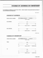
vehicle. We suggest that this manual remain with the
vehicle at the time of resale and that PREVOST CAR-
ING. be informed of such a sale in
order
to update its
file. Use the appropriate form at the end of this manual.
All
information
and
specifications in this
manual
are current at time of printing. However, because of
PREVOST's policy of continual improvement, we re-
serve the right to make changes at any time without
notice.
Please note that this manual applies to bus shells manu-
factured by
PREVOST CAR INC. and explains all equip-
ment including options installed in
our
factory. Therefore,
you
may find explanations for equipment not installed
on your vehicle.
It
does not explain equipment installed
by your converter.
FOREWORD
This material may not be reproduced
or
copied in
whole
or
in part without the written permission of
PREVOST CAR INC.
The following symbols and wordings are used to
emphasize particular information:
•
WARNING:
Identifies instructions which if not fot-
lowed, could cause personal injury.
•
CAUTION:
Denotes instructions which if not fol-
lowed, could severely damage vehicle components.
0
NOTE:
Indicates supplementary information needed
to fully complete an instruction.


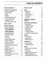
TABLE OF CONTENTS
Recommendations . . . . .
..
. . . . . . . . . 9 Cruise control ..
..............
...... 22
Controls & instruments .......... 10 Seats
..
...............................
23
-Driver's compartment . .
...............
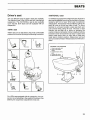
10 -Driver's seat
....
...
...................
23
-Indicator lights .
.......
...
.
..
.
..
... ...
11
-
cclSRln
seat . .
....
. .
...........
.
.......
23
-Gages
................
. . . . .
..
..
..
.....
12 -
ccNATIONALn
seat
...
.
......
..
........
23
-Switches
.............................
13
-Co-pilot's seat
..............
.
.........
24
-Steering column controls
.......
.
.....
15 -Seat belts
............................
24
-Foot operated controls
............
.
..
15
-Dashboard controls
.....
.
.............
15
Windshield wipers &
washers
..............................
2s
-Side switch panel controls
............
17
Alarm system
.......................
11
Automatic transmission ......... .
26
-Lockup clutch
........................
26
Engine operation
..................
10 -Accelerator control .
..................
26
-Engine compartment
...........
.
.....
18 -Downshift control
....................
.
26
-Starting engine from
driver's compartment
.................
18 -Deceleration
..........................
27
-Oil level check
.......................
27
-Starting engine from
engine compartment
..................
19 -Oil check procedure
.......
.
.......
...
27
-Cold weather starting
................
. 19 -Transmission oil specifications . .
....
..
27
-Engine block heater
.......
.
........
. . 19 Brakes .......... .
..
..
... ........ .
..
.
..
20
-Warm-up
.............................
20
-Service brakes
..
..
..............
.....
28
-
Air
pressure
..........................
20
-Parking brakes
.......................
28
-Engine oil specifications
..............
20
-Emergency brakes
............
.
.......
28
-Engine oil pressure
...................
20
-Engine
oil
level check
................
20
Suspension
.........................
29
-Engine temperature
..................
20
-Level
low
system
..
. .
.................
29
-Optional engine brake system . .
......
20
-Retractable tag axle
..................
29
-Alternator
...........
. .
............
.
..
21
Lights
.................................
30
-Engine alarm system
.................
21
- Head, markers and tail lights
..........
30
-Stopping engine
......
.
...............
21
-Fog lights .
..
.
.............
...
....
.
...
30
-Engine emergency stop
......
..
......
21
-Driver's lights ..
............
..
....
.
....
30
-
Belt
tensioners
......................
.
21
-Baggage compartment lights .
........
30
-Air system emergency fill valve
.......
22
-Directional signal switch . .
............
30
-Power steering
.......................
22 -Hazard warning flasher switch
........
30

Heating & air conditioning ..
..
. 31
-Driver's compartment heating
and
A/C
system ..
...
..
. .
..
. .
.......
..
31
-Central heating and
A/C
system .
...
..
32
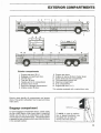
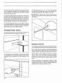
Exterior compartments ..... .
.. ..
33
-Baggage compartment
........
. . . . .
..
.
33
-Battery compartment . . . . . .
...
..
. . .
...
34
-Engine compartment
..
.
...
....
.
....
..
34
-Spare wheel and tire compartment
...
34
-Emergency exit . . .
.......
....
.
.....
...
35
-Entrance door .
......
.
...
.
....
.
.......
35
-Compartment
doors
.....
..
. . .
... ...
.
36
-Exterior mirrors
..
. . .
............
.....
.
36
-Trailer hitch . . . .
.....
..
............
37
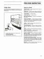
Pre-ride inspection .........
..
.... 37
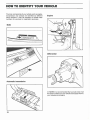
How
to
identify
your vehicle ................ ....... .
38
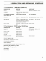
Lubrication & servicing
schedule .
...........................
.
39
Technical data
...............
..
.... 41
Light bulb data .
..
.
..............
..
.
42
Owner's assistance .... ... ........
43
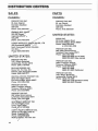
Distribution centers ... ......... ..
44
-Sales
....
. . .
.....
.......
...
.
.....
.
..
..
44
-Parts
.. ..
.
.............
..
..
.
..
.
..
. . . . .
44

We suggest the following :
-Make sure the basic principles of operation of
your
vehicle are understood.
-Maintain
your
vehicle in
good
running condition.
-Do not drive your vehicle with an extremely low fuel
level. This advice is very important, especially if your
vehicle is equipped with an auxiliary tank.
-Only perform procedures as detailed in this manual;
unless otherwise specified, engine should be turned
OFF for all lubrication and maintenance procedures.
-Do not attempt to push
or
pull-start your vehicle.
-Fire extinguishers are located just behind the driv-
er's seat. In case of fire, evacuate the vehicle then take
the time to think before you attempt to fight the fire.
-The Gross Vehicle Weight (GVW) and the Gross
Axle Weights (GAW) of your vehicle appear on the
certification plate mounted
on
the wall at the left of the
driver. These values are carrying capacities, which
safely exceed the loads to be carried,
i.e.
the loads
permitted on U.S. roads.
RECOMMENDATIONS
•To
exceed theG.V.W.R.and/ortheG.A.W.
R.
. voids
the PREVOST warranty.
• For unloaded vehicle and axle weight specifications,
please refer to the document which is included in
the technical publications box.
• DO NOT conceal the certification plate.
If
neces-
sary, reinstall over the trim.
-Installation of odd type and size of windows requires
cutting the vertical window posts located on 45 5/ 16"
centers on LE MIRAGE model. However,
no
more
than three (3) of these posts should
be
cut on one side
of a vehicle and never
cut
two (2) adjacent posts.
IMPORTANT
Violation of these instructions is not safe and consti-
tutes sufficient reason for PREVOST
to
void its
war
-
ranty on any affected area.
9

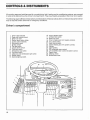
CONTROLS &
INSTRUMENTS
All controls, gages and switches used
for
normal driving, light, heating
and
air conditioning systems, are arranged
in what will be referred to as the uDriver's Compartment». They are all readily accessible
to
the
driver
when seated.
The following pages
will feature descriptions and illustrations
of
these as well as other controls and equipment which
may be required
under
abnormal
or
emergency
conditions.
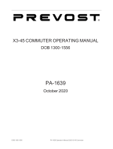
Driver's compartment
10
1. Driver's light rheostat.
2.
Gage and indicator panel.
3. Driver's air vent.
4.
Electric push button shifter.
5.
Cruise control switches.
6.
Side switch panel.
7. Ignition switch.
B.
Fast
idle switch.
9.
Jacobs brake switch .
10. Cold start switch.
11. Emergency stop switch.
12. Fog lamp switch.
13. Clearance and identification light switch.
14. Blinker switch.
15. General lighting switch.
16. Hazard flasher switch.
17
. Air
door
locK switch.
18. Driver's air
vent.
19. Driver's heating and
A/C
system controls.
20.
A/C
clutch switch.
21. Water
pump
switch.
22
. Central heating and
A/C
system controls.
23. Ashtray.
24
. Cigar lighther.
25.
RH
windshield wiper control.
26. LH windshield wiper control & washer control.
27. Electric horn.
28. Steering wheel.
29. Multifunction lever.
~~~~~~====~~~26
=
25
~~;;;;;;;;~~~~~~H-24
~[l-....;:!~t--
23
=~-22
21
20

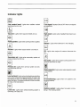
Indicator lights
Low
coolant
level: Lights when radiator coolant
level becomes too low.
~
Tag-axle:
Lights when tag axle wheels are up.
[§]
Parking
brake:
Lights when parking brake
is
applied.
~
Hazard:
li
ghts when hazard switch is turned on.
~
Secondary
air:
Lights when secondary system air
pressure becomes too low.
~
Primary
air: Lights when primary system air pres-
sure becomes too low.
Low
fuel
level: Lights when fuel level does
not
allow
you to cover a distance of approximately 75 miles
(120
kilometers)
or
more. On vehicles equipped with a 250
gallon fuel tank, the distance allowed
is
approximately
90
miles
(150
kilometers).
~
~
Level
low:
Lights when vehicle levelling system is
operating (see page 29).
Turn
signal:
Flashes ON and OFF when turn signals
are operating.
~
High
beam:
Lights when headlight high beams are
selected.
Battery: Lights when alternator is not charging.
B
Oil: Li
ght
s when engine oil pressure becomes too
low.
Hot
water:
Lights when engine cooling system tem-
perature becomes too high.
Water
separator:
Lights when water separator needs
to be drained.
[Ale]
Air
conditioning:
Lights when
A/C
system
is
not
working properly.
'~
_,.
-·-
-"
f'
Heating
system:
Lights when hot water is circu-
lating in the heating system.
11

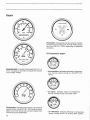
Gages
Speedometer: Indicates
drivin~
speed in
M
.
P.~.
~r
km/h
.
It
includes an odometer to indicate the vehicles
accumulated mileage.
Tachometer: Indicates engine speed in hundreds of
revolutions per minute {
R.P
.M.). Use it while driving to
select correct shift points and to prevent engine from
overreving during deceleration.
12
Pyrometer: Indicates left and right
exhau~t
manifold
temperature in hundreds of °F. Normal reading should
vary from
500°F
to
1100°F
depending on operating
conditions.
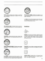
Oil temperature gages:
-
for
transmission:
indicates transmission oil tempera-
ture. Normal reading should be 160-250°F
(70-
1200C).
-for engine: Indicates engine oil temperature.
Normal reading should not exceed
250°F
.
-for differential: Indicates differential all temperature.
Normal reading should not exceed
2500F
(1200C).

Turbo gage: Indicates turbo pressure in inches of
Hg
or
psi. Reading depends on engine R.P.M. and
load conditions.
Oil
pressure
gage: Indicates engine oil pressure.
Normal reading should be 35-75 psi (240-280 kPa).
Voltmeter: Indicates electrical system voltage. With
engine operating, normal reading should be 24-27.5
volts.
Water temperature gage: Indicates engine coolant
temperature. Normal reading should be 170-195°F
(76-90°C).
Fuel gage: Indicates approximate Quantity of fuel
remaining
in
fuel tank.
It
is not recommended to operate
the vehicl e when
th
e reading is below roughly
Mi
full.
Air pressure gage: Indicates air pressure in air
system. Normal reading should vary from
90
to 125 psi
(620 to 860 kPa).
0 NOTE: Two air pressure gages are used. The upper
one indicates primary circuit air pressure. The lower
one is
for
the secondary circuit.
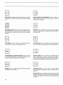
Switches
OFF
•
Ignition: This switch will activate electrical circuits
when key is in ON position. To start engine, rotate key
to ST ART position then release it as soon as engine
starts. Turn key to «OFF» position to stop engine and
all electrical circuits.
Fast
idle: Push on button
to
engage engine
fas
t idle
increasing idle to
950
RPM
. Push again on button to
disengage.
B
Jacobs
brake: Activates half
or
full engine brake
system by respectively pushing on button once
or
twice. Push again to disengage.
13

BJ
Cold
start:
Activates ether cold start device in engine
compartment. (Refer to cold weather starting
on
page
19)
.
Emergency
stop:
Push
on
button to engage engine
stop mechanism if engine turns
out
of
control. This is
for emergency use only (not required
on
turbocharged
engine.).
Fog
lamp:
Push
on
button to operate fog lamps.
Push again
on
button to disengage circuit.
Identification
& clearance
light:
Push
on
button
to operate identification and clearance lights. Push
again on button to obtain
«OFF»
position.
IUNMER
COURTOIS
lt
Blinker:
Push on button to activate blinkers and release
to obtain
«OFF»
position.
14
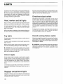
Head
marker
and
tail
lights:
Push
on
button to
activate night and day lights. Push again
on
button to
obtain
ccOFF»
position.
Hazard:
Push
on
button to cause all turn signal lights
to flash simultaneously. Indicator light will also flash
(see page 30).
Air
door
lock:
Push
on
button to lock the entrance
door
. Push again to disengage the locking mechanism.
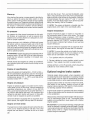
Driver's
light:
Push on button to operate driver's
lights. Push again on button to obtain
OFF
position.
Driver's lights can also
be
operated by the other switch
located on the dashboard near the entrance door.
Heating
mirror:
Push
on
button to heat outside
mirror
system. Push again
on
button to obtain
«OFF»
position.
• CAUTION:
Do
not install any convex
mirro
r over the
heating
mirror
glass. This prevents the even distribution
of heat in the heating
mirror
and could cause the glass
to break.

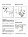
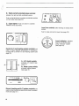
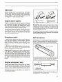
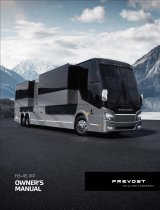
Steering
column
controls
al.INKER
OR
HORN
LE"
TUAN
SIGNAL
A. "Multifunction" lever is used to operate the fol-
lowing accessories:
1.
Turn signal: move the lever
up
to the second stop
to signal a right turn, move it
down
to the second stop
to signal a left turn. When the turn is completed, the
signal will cancel and the lever will return to horizontal.
2.
Lane change signal: move the lever part way to the
first stop, and hold it there. The lever will return to
horizontal when you release it.
3.
Headlight beam changer: high beam
or
low beam
can
be
selected
by
respectively pushing the lever
towards the dashboard
or
pulling it towards the driver.
High beam can be flashed momentarily by pulling the
lever completely towards the driver and then releasing
it.
4.
Electrical horn:
on
vehicles so equipped, electrical
horn
can be operated by pressing the button located at
the lever tip.
5. Blinkers: on vehicles so equipped, blinkers can be
operated by pressing the button located at the lever tip.
0
NOTE:
Your
vehicle is equipped with only one
of
the two above-mentioned features
(#4
or
#5).
B. Electrical horn: can be operated by pressing
the button at the center
of
the steering wheel.
Foot
operated
controls
A B
A.
Brake pedal: applies service brakes.
B.
Accelerator pedal: controls engine R.P.M.
C.
Air horn valve: sounds air horn.
Dashboard
controls
A.
Dash
light
rheostat:
controls instrument and
switch panel illumination lrght intensity.
15

A
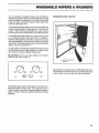
B.
Right
and
left
windshield
wiper
controls:
activate the right and left windshield wipers.
Push on the left button to activate windshield washers
on both sides (see page 25).
C.
Cigar
lighter:
Push on button to operate.
Release will be automatic.
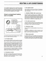
Central
A/C
and
heating
system
controls:
are
used to obtain desired temperature
in
vehicles e-
quipped with a centra' A/ C and
he
ating system (see
page 32).
-,
I
LJ
·-·
-
---B
A.
A/C
clutch
switch:
activates
A/C
system (see
page 31).
B.
Water
pump
switch:
activates heating system
(see page
31
).
Driver's
heating
and
A/C
system
controls:
are
used
to
obtain desired temperature in driver's compart-
ment (see page 31).
16
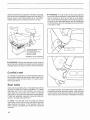
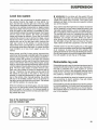
Level
low
controls:
allow leveling of vehicle when
parked.
Push to raise and pull to lower (see page 29).
Level
indicator:
indicates
level of the vehicle when
using "level
low
" system
(see page 29).

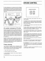
Side
switch
panel
controls
TRANSMISSION
®S~~e
;~
NO
0
R0
9
A.
Automatic
transmission
electrical
shifter:
aHows
proper selection of the transmis-
sion range electrically
(see page 26).
B.
Cruise
control:allows selec-
tion of desired cruising speed
(see page 22).
The following controls are located at the left of the
dr
iver's seat:
A B c
A.
Automatic
transmission
shifter
lever:
allows
proper serec
ti
on of the transmission range (see page
26
).
D NOTE: The shifter lever may be located at right of
the driver's seat upon request.
B.
Tag
axle
switch:a
llows the raising
or
the l
ow
-
ering of the
tag
ax
te wheels. (see page 29).
C.
Parking
brake
valve:
allows application or parking
brake.
-PULL to apply.
-PUSH to release.
(see page 28).
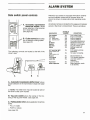
ALARM
SYSTEM
PREVOST bus shells are equipped with alarm systems
sucn as indicator lamps
and/or
buzzers which ins
inform the driver of cenain abnormal operating condi·
lions.
All indicator lamps are located on the ugage and indicator
panel»
1n
the drivers compartment. They are
as
follows:
AUDIBLE
INDICATOR ALARM CONDITION
Low coolant
No
Low coolant level.
Hot
waler
Yes Engine overheating.
Air
Pfl-ry
cln:ult
Yes
Low air pressure_
HCOndary circuit Yes Low air pressure_
011
Yes
Low engine oil pressure.
Hl·Beam
No
Headlamp hi-beam
"'
on
".
Battery
No
Alternator not charging.
Tag
axle
Yes Tag axle wheels up.
Brake
No
Parking brakes are
applied.
A/C
wamlng
ll~hl
No
A/C
system working
(central
system
0
11ty>
improperly_
Heat
No
Hot water circulating .
(cenlral
syslem
o
rll
y>
J
Hazard No Hazard llashers
on
_
Turn signal No Turn signals operating.
Level
low
No Level low system in
operation.
Fuel level
No
Low fuel level.
Waler
separator
No
Water separator needs
to
be
drained.
17

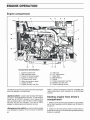
ENGINE OPERATION
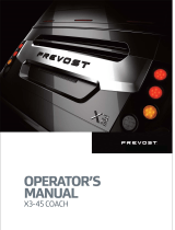
Engine
compartment
1
16
15
2
13 12
Component identification:
1 . Engine coolant tank
2.
Rear electrical panel
3.
Engine oil pressure gage
4. Engine
011
reserve tank
5.
O
il
reserve tan k valve
6. Water temperature gage
7.
Engine air filter
8.
Engine primary fuel filter
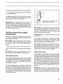
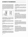
The following controls are used to start and stop engine
from the operator's compartment.
ctlgnition
switchn
is used to start and stop the engine,
and also to activate electrical circuits. To start engine,
rotate key to
11STARTn
position. then release it as
soon
as
engine starts. With key set to
ccON11
posiUon.
electrical circuits are activated. Turn key to
uOFF11
position to stop engine and electrical circuits.
<CEmergency
stop
switch>1
is used to stop the engine
in
an
emergency situation. Push
on
button to activate.
18
3 4 5 6
11
10 9
9. Alternator
10.
A/C
compressor
11
. Water filter
12. Belt tensioner
13
. Muffler
14. Engine secondary fuel filter
15. Radiator fan gear box
16. Power steering oil tank.
1
8
Refer to uEngine emergency
stop11
for complete ope-
rating instructions
(not
required
on
turbocharged
engine).
Starting
engine
from
driver's
compartment
1. Make sure the remote control switch in rear panel is
set for front operation and the battery cut off switch is
turned on.
2. Make sure that the parking brake control button is
pulled all the way up, so that the spring loaded parking
brakes are applied.
Page is loading ...
Page is loading ...
Page is loading ...
Page is loading ...
Page is loading ...
Page is loading ...
Page is loading ...
Page is loading ...
Page is loading ...
Page is loading ...
Page is loading ...
Page is loading ...
Page is loading ...
Page is loading ...
Page is loading ...
Page is loading ...
Page is loading ...
Page is loading ...
Page is loading ...
Page is loading ...
Page is loading ...
Page is loading ...
Page is loading ...
Page is loading ...
Page is loading ...
Page is loading ...
Page is loading ...
Page is loading ...
Page is loading ...
Page is loading ...
Page is loading ...
Page is loading ...
Page is loading ...
Page is loading ...
-
 1
1
-
 2
2
-
 3
3
-
 4
4
-
 5
5
-
 6
6
-
 7
7
-
 8
8
-
 9
9
-
 10
10
-
 11
11
-
 12
12
-
 13
13
-
 14
14
-
 15
15
-
 16
16
-
 17
17
-
 18
18
-
 19
19
-
 20
20
-
 21
21
-
 22
22
-
 23
23
-
 24
24
-
 25
25
-
 26
26
-
 27
27
-
 28
28
-
 29
29
-
 30
30
-
 31
31
-
 32
32
-
 33
33
-
 34
34
-
 35
35
-
 36
36
-
 37
37
-
 38
38
-
 39
39
-
 40
40
-
 41
41
-
 42
42
-
 43
43
-
 44
44
-
 45
45
-
 46
46
-
 47
47
-
 48
48
-
 49
49
-
 50
50
-
 51
51
-
 52
52
-
 53
53
-
 54
54


PREVOST Marathon/Mirage Owner's manual
- Category
- Cars
- Type
- Owner's manual
- This manual is also suitable for
Ask a question and I''ll find the answer in the document
Finding information in a document is now easier with AI
Related papers
-
 PREVOST H3-45 VIP Owner's manual
-
 PREVOST X3-45 VIP Owner's manual
-
 PREVOST H3-45 VIP Owner's manual
-
 PREVOST X3-45 Commuter Owner's manual
-
 PREVOST X3-45 Commuter Owner's manual
-
 PREVOST H3-45 VIP Owner's manual
-
PREVOST H3-45 Incomplete Owner's manual
-
 PREVOST X3-45 Owner's manual
-
-


