
Product Materials:
Polyamide
O-Ring: Nitrile
NOTE:
The standard thread pitch up to and including the
M75 size is 1.5mm.
For Increased Safety Enclosures
Ensure the stopping plug thread is compatible with the enclosure thread. If the enclosure contains a clearance hole entry, the
maximum clearance permitted between the enclosure entry hole and the stopping plug nominal thread size is 0.7mm. Ensure that
the area around the enclosure entry thread is clean and at and the entry thread is square to the enclosure face.
For Threaded Entries in Exe Enclosures
Insert the stopping plug from the outside of the enclosure and fully tighten using the correct size of Allen key.
For Clearance Entries in Exe Enclosures
Insert the stopping plug from the outside of the enclosure. Fit a locknut of the same thread type and size onto the stopping plug
thread within the enclosure and using the correct size of Allen key and a suitable spanner or wrench tighten the stopping plug fully.
SPECIAL CONDITIONS FOR SAFE USE
1. The maximum operating temperature range of
the stopping plug when tted with a nitrile
O-ring is -60°C to +75°C.
2. When the stopping plug is tted in plain holes
in increased safety or dust protected
enclosures, the sealing face of the enclosure is
to be smooth and the hole no larger than
0.7mm above the major diameter of the male
thread on the stopping plug. The stopping plug
is to be secured with a locknut and optional
locking washer.
3. When tted in threaded holes, the sealing face
of the enclosure is to be smooth, the threaded
hole perpendicular to the wall of the enclosure
and the thread medium t.
4. Sizes M50, M63 and M75 - Warning: static
ignition risk, clean only with a damp cloth.
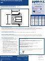
THREAD DETAILS
M20 28.0
M16 24.0
33.0
50.0
40.0
60.0
85.0
73.0
M25
M32
M40
M50
M63
M75
Thread Size
Metric
Outside
Diameter
10
8
10
10
10
10
10
10
15.0
15.0
15.0
15.0
15.0
15.0
15.0
15.0
Allen Key
Size
Thread
Length
Thread Length
Thread Size
Operating temperature range -60°C +75°C
II 2 GD Ex eb IIC Gb Ex tb IIIC Db
Baseefa12ATEX0095X IP66/67
BAS21UKEX0053X
IECEx BAS12.0065X
IEx No: 15.0291X
No EA3C RU C-GB.HA91.B.00265/21
c CSA us No: 2700364
Class I Zone 1 AExeb IIC Gb
Zone 21 AExtb IIIC Db IP66/67
Certication Details
AI 410 - Issue M / Page 1 of 1
AI 410 / Issue M - 12/21
Assembly Instructions for stopping plug:
375
Declaration of Conformity in accordance with European Directive 2014/34/EU and UK
Statutory Instrument 2016/1107
Provisions of the Directive fullled by the Equipment: II 2 GD Ex eb IIC Gb Ex tb IIIC Db
Harmonised Standards used: EN IEC 60079-0:2018, EN IEC 60079-7:2015+A1:2018,
EN60079-31:2014
Notied Body for EU-Type Examination: SGS Fimko 0598 Helsinki Finland
EU-type Examination Certicate: Baseefa 12ATEX0095X
Notied Body for Production: 0598
Approved Body for UK-Type Examination: SGS Baseefa 1180 Buxton UK
UK-type Examination Certicate: BAS21UKEX0053X
Approved Body for Production: 1180
On behalf of the above named company, I declare that, on the date the equipment accompanied
by this declaration is placed on the market, the equipment conforms with all technical and
regulatory requirements of the above listed directives.
………………………………….
A. Reid
Technical Manager
Connection Solutions
Hawke International is a division of Hubbell Ltd.
Registered No. 669157 in England. Registered Oce:
Cannon Place, 78 Cannon Street, London EC4N 6AF.
A member of the Hubbell Group of Companies
www.ehawke.com
UK Oce
Oxford Street West,
Ashton-under-Lyne,
Lancashire. OL7 0NA. UK
Product supplied may dier
slightly from that shown.
Images are for illustration
purposes only.
Tel: +44 (0) 161 830 6695
-
 1
1

Ask a question and I''ll find the answer in the document
Finding information in a document is now easier with AI
Related papers
-
Hawke 487 Installation guide
-
-
-
-
-
-
-
-
-
Other documents
-
CMP PXRC Compound Barrier Cable Gland Installation guide
-
-
-
-
-
-
-
-
-