Page is loading ...

Rev F Date: 10.4.2018
I:\Manuals\Reveal_Over-Under Combo Case 20-78347.pub
Structural Concepts Corporation ∙ 888 E. Porter Road ∙ Muskegon, MI 49441 Phone: 231.798.8888 Fax: 231.798.4960 ∙ www.structuralconcepts.com
SCC P/N
20-78347
READ AND SAVE
INSTALLATION
AND OPERATING
MANUAL
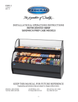
REVEAL® FREE STANDING OVER-UNDER REFRIGERATED COMBO MERCHANDISERS
> CONVERTIBLE UPPER SECTION MAY BE EITHER AMBIENT OR REFRIGERATED
> REFRIGERATED LOWER SECTION
> SELF-CONTAINED OR REMOTE UNITS
> UPPER SECTION: REAR SLIDING DOORS
> OPTIONAL RISERS (IN LIEU OF SHELVING)
> LOWER SECTION: REAR SLIDING DOORS WITH
PERFORATED ACRYLIC PLENUMS OR SOLID BACK PANELS
> CAUTION! DO NOT PUSH OR PULL ON UPPER GLASS ENCLOSURE!
> ONLY USE HANDLES (AT EACH END OF CASE) TO PUSH OR PULL CASE INTO POSITION!
Models Are Shipped WITHOUT
Panels and Cladding Attached.
See Pages 10 & 11 For Component
Attachment Instructions.
Reveal
®
Reveal® Model NR3631RRSSV
Self-Service Solid Back Rear Panel
Optional Product Steps / Shown As Shipped
From Factory (Without Components) / Front
Slide-Out Access To Condenser Package
Reveal® Model NR3631RRSSV /
Rear Sliding Doors and Acrylic
Perforated Plenums / Shown As Shipped
From Factory (Without Components) / Rear
Slide-Out Access To Condenser Package
Reveal® Model
NR4838RRSSV
Rear Sliding Doors and
Acrylic Perforated
Plenums / Cladding
Shown Attached

2
TABLE OF CONTENTS
TABLE OF CONTENTS …………………………………………………………………………………...…...
REVEAL® REFRIGERATED OVER-UNDER COMBO MODEL APPLICABILITY & DIMENSIONS ..
OVERVIEW / DISPLAY TYPE I vs. II / COMPLIANCE / WARNINGS / PRECAUTIONS ……………...
INSTALLATION: TOE-KICK & GRILLE REMOVAL / DISONNECTING CASE FROM PALLET …….
INSTALLATION, CONT’D: CASTER ADJUSTMENT / LOCK / UNLOCK / CASE REMOVAL
FROM PALLET .……….………………………………………………………………………..……...
INSTALLATION, CONT’D: SHELVING ASSEMBLY COMPONENTS ...………………………………...
INSTALLATION, CONT’D: MAIN POWER SWITCH / TOE-KICK & AIR INTAKE GRILLE / PLUG-IN
INSTALLATION, CONT’D: SHIPPING BRACE / ATTACHING FRONT PANEL COMPONENTS /
HANDLES ……………………………………………………………………………………………….
INSTALLATION, CONT’D: ATTACHING SIDE PANELS, REAR PANEL AND REAR GRILLE ……..
INSTALLATION, CONT’D: OPTIONAL ACRYLIC SECURITY COVER ………………………………...
CASE DESIGN: FRONT OF CASE (UNITS WITH LOWER REAR DOORS) .......................................
CASE DESIGN, CONT’D: REAR OF CASE (UNITS WITH LOWER REAR DOORS) ..……………….
CASE DESIGN, CONT’D: CONTROLLER / DC DRIVERS / MAIN POWER SWITCH /
CONDENSER COIL FILTER ….………………………………………………………………………
CASE DESIGN, CONT’D: NIGHT CURTAIN ACCESS AND OPERATION ……………………………..
CASE DESIGN, CONT’D: TUB AREA (AFTER DECK PAN REMOVAL) ……………………………….
CASE DESIGN, CONT’D: LED LIGHT SWITCH LOCATIONS / LED LIGHTS / THERMOMETERS ..
CASE DESIGN, CONT’D: REAR SLIDING DOOR REMOVAL / REAR PERFORATED PLENUM
CONTROL ………………………………………………………………………………………………
CASE DESIGN, CONT’D: CONDENSER PACKAGE (SELF-CONTAINED UNITS ONLY) …………..
PRODUCT PLACEMENT / UPPER SECTION & HONEYCOMB AIRFLOW / LOAD LINES ………….
CLEANING SCHEDULE (TO BE PERFORMED BY STORE PERSONNEL) ..…....…...…………...….
PREVENTIVE MAINTENANCE (TO BE PERFORMED BY TRAINED SERVICE PROVIDER) ……....
TROUBLESHOOTING (TO BE PERFORMED BY STORE PERSONNEL ONLY) ...………………......
TROUBLESHOOTING (TO BE PERFORMED BY TRAINED SERVICE PROVIDERS ONLY) ……….
TROUBLESHOOTING (TO BE PERFORMED BY TRAINED SERVICE PROVIDERS ONLY) -
CONDENSING SYSTEM ..………………………………………………………………………...….
TROUBLESHOOTING (TO BE PERFORMED BY TRAINED SERVICE PROVIDERS ONLY) -
EVAPORATOR SYSTEM ...…………………………………………………………………………...
SERIAL LABEL INFORMATION & LOCATION ..…………………………….……...…....……………..…
TEMPERATURE CONTROLLER - CAREL® ...…..……………………..…….……………………..……..
TECHNICAL SERVICE CONTACT INFORMATION & WARRANTY INFORMATION ...…...…...….....
2
3
4-5
6
7
8
9
10
11
12
13
14
15
16
17
18
19
20
21
22
23-25
26-27
28-31
32
33
34
35-37
38

3
REVEAL® REFRIGERATED OVER-UNDER COMBO MODEL APPLICABILITY & DIMENSIONS
Model Upper Display
Case Height Overall Case Height Case Depth x Width
NR3651RRSSV 16” 50 3/4” 33”D* x 35 3/4”W
NR3658RRSSV 16” 57 1/2” 33”D* x 35 3/4”W
NR4851RRSSV 16” 50 3/4” 33”D* x 47 3/4”W
NR4858RRSSV 16” 57 1/2” 33”D* x 47 3/4”W

4
OVERVIEW / DISPLAY TYPE I vs. II / COMPLIANCE / WARNINGS / PRECAUTIONS - PAGE 1 of 2
WARNING
Hazardous moving parts. Do not operate unit with covers removed.
Fan blades may be exposed when deck panel is removed.
Disconnect power before removing deck panel.
WARNING
Risk of electric shock. Disconnect power before servicing unit.
CAUTION! More than one source of electrical supply is
employed with units that have separate circuits.
Disconnect ALL ELECTRICAL SOURCES before servicing.
WARNING
ELECTRICAL
HAZARD
WARNING
KEEP
HANDS
CLEAR
OVERVIEW
• These Structural Concepts Reveal® cases are
designed to merchandise packaged products at
40 °F (4 °C) or less product temperatures.
• Cases should be installed and operated according to
this operating manual’s instructions to insure proper
performance. Improper use will void warranty.
TYPE I vs. TYPE II ENVIRONMENTAL CONDITIONS
This unit is designed for the display of products in
ambient store conditions where temperature and
humidity are maintained within a specific range.
• Type I display refrigerators are intended for use in an
area where environmental conditions are controlled
and maintained so that the ambient temperature does
not exceed 75 °F (24 °C) and 55% maximum humidity.
• Type II display refrigerators are intended for use in an
area where environmental conditions are controlled
and maintained so that the ambient temperature does not
exceed 80 °F (27 °C) and 55% maximum humidity.
• If unsure if your unit is Type I or II, see tag next to serial
label. See SERIAL LABEL LOCATION & INFORMATION
LISTED / TECH INFO & SERVICE section in this
manual for sample serial labels.
COMPLIANCE
• Performance issues when in violation of applicable
NEC, federal, state and local electrical and plumbing
codes are not covered by warranty.
• See below compliance guideline.
WARNINGS
• Please read the important warnings in this document
carefully as they can prevent injury or death.
• See next page for PRECAUTIONS.
COMPLIANCE
This equipment MUST be installed in compliance with
all applicable NEC, federal, state and local
electrical and plumbing codes.
ATTENTION
CONTRACTORS
CAUTION! IF YOUR UNIT IS SELF-CONTAINED, YOU MUST
CHECK CONDENSATE PAN POSITION & PLUG!
Water on flooring can cause extensive damage!
Before powering up unit, check and confirm that:
• Condensate pan is DIRECTLY UNDER condensate drain.
• Condensate pan plug is securely plugged into receptacle.
• Overflow pan has plug connected to its box. Units with
optional Clean Sweep® MUST HAVE two plugs connected.

5
OVERVIEW / DISPLAY TYPE I vs. II / COMPLIANCE / WARNINGS / PRECAUTIONS - PAGE 2 of 2
PRECAUTIONS
• Following are important precautions to prevent
damage to unit or merchandise.
• Please read carefully!
• See previous page for specifics on OVERVIEW, NSF
TYPE, COMPLIANCE and WARNINGS.
CAUTION! ADVERSE CONDITIONS / SPACING ISSUES
• Performance issues caused by adverse conditions are NOT covered
by warranty.
• End panels must be tightly joined or kept at least 6-inches away from
any structure to prevent condensation.
• Unit must be kept at least 15-feet from exterior doors, overhead HVAC
vents or any air curtain disruption to maintain proper temperatures.
• Do not expose to direct sunlight or heat source (ovens, fryers, etc.).
CAUTION
CAUTION! LAMP REPLACEMENT GUIDELINES
LED lamps reflect specific size, shape and overall design.
Any replacements must meet factory specifications.
CAUTION
WIRING DIAGRAM FORMAT & LOCATION
• Each case has its own wiring diagram folded & in its own packet.
• Wiring diagram placement may vary; it may be placed near field
wiring box, raceway, or other related location.
CAUTION!
DO NOT RELY ON THERMOMETERS OR THERMOSTATS
FOR ACTUAL PRODUCT (FOOD) TEMPERATURES.
• Thermometers and thermostats reflect air temperatures ONLY.
• For PRECISE food temperatures, use calibrated food
thermometers ONLY.
CAUTION! GFCI BREAKER USE REQUIREMENT
If N.E.C. (National Electric Code) or your local code
requires GFCI (Ground Fault Circuit Interrupter) protection,
you MUST use a GFCI breaker in lieu of a GFCI receptacle.
CAUTION!
• To prevent sagging or breakage, do not exceed 5 LBS (2.3 KG)
weight load per top glass section (between vertical supports).
• To prevent scratching or marring, do not place ANY items on glass.
5
LBS

6
INSTALLATION: TOE-KICK & GRILLE REMOVAL / DISONNECTING CASE FROM PALLET
Toe-Kick
Air Intake Grille
1. Remove Front Toe-Kick From Case
• To prevent damage to case, remove front
toe-kick from case before removing from pallet.
• Toe-kick is held in place by magnets only. No
screw removal is required.
• Place front toe-kick in secure location while
removing case from pallet.
2. Remove Air Intake Grille From Case
• To prevent damage to case, lift air intake grille
UP and OFF case.
• Air intake grille is held in place by magnets.
No screw removal is required.
• Place air intake grille in secure location
while removing case from pallet.
3. Disconnect Case From Pallet
• Use Phillips driver to remove screws
from shipping brackets. Remove and
discard shipping brackets from pallet.
• Place J-bar/pry bar under base frame.
Raise case up from pallet to take
weight off casters.
• With case raised, lower casters all the
way down against pallet (see next
step for detailed instructions on
lowering or raising casters).
• Remove rubber shipping blocks.
Pallet
Rubber
Shipping Block
Shipping
Bracket

7
4. Caster Height: Raising and Lowering
• Raise or lower casters (to adjust case height) by
rotating casters’ vertical adjustment rings.
• Rotate vertical adjustment ring clockwise to lower
caster (and increase height of case).
• Rotate vertical adjustment ring counter-clockwise
to raise caster (and decrease height of case).
5. Caster Rolling Capability: Unlocking
• Important! Case is shipped with caster mechanisms
factory set at ON (locked) to prevent case from
rolling.
• Unlock casters by pressing OFF on the caster
mechanism.
• See illustration at right.
6. Carefully Remove Case From Pallet
• Check that casters are lowered as far down as they
will go (as instructed in step #4).
• Use handles to carefully slide case to rear of pallet
(see illustration at right).
• Caution! 4 people are required for this task!
• Carefully lower to floor (using ramp if available).
• Slide pallet from under case as required.
• Maintain support of case at all times or center
of gravity may cause case to fall.
• See illustration at right.
7. Casters: Locking
• After case is at desired position (and height),
use level to check that case is level and plumb.
• Readjust height as needed (as instructed in
step #4).
• Locking Height: After proper height (and positioning)
of case is attained, tighten the two (2) set screws to
lock each caster’s height in place.
• Locking Movement: Then, to prevent casters’ rolling
capability, lock casters by pressing ON atop the “ON”
and “OFF” lever mechanism (shown at right). Case
will now be secured at its new location.
Vertical
Adjustment
Ring
Pallet
Support case
while removing
from pallet
Caster
Tighten Set
Screws To
Lock Caster
Height In
Place
Press “ON” Lever To
Lock Caster In Place
(And Prevent Caster
From Rolling)
Press “OFF” Lever To
Unlock Caster (And
Allow Casters To Roll)
Caster
Caster
INSTALLATION, CONT’D.: CASTER ADJUSTMENT / LOCK / UNLOCK / CASE REMOVAL FROM PALLET
Handles
Ramp

8
INSTALLATION, CONT’D: SHELVING ASSEMBLY COMPONENTS INSTALLATION, CONT’D: SHELVING ASSEMBLY COMPONENTS
8. Shelving Assembly Components
• Check that glass shelving is in proper position
before placing product in case
• Shelves may be adjusted vertically or entirely
removed from merchandiser.
• Metal shelving brackets ARE NOT able to be
angled. They are at a fixed 90° position.
• There are 12 components comprising each
shelf assembly:
A. Right bracket (with hooks to attach to slots in
upright)
B. LED light with magnets
C. Front shelf support rail (LED light attaches to
its inner cavity via magnets)
D. Cover (rests atop front shelf support rail)
E. Left bracket (hooks to attach to slots in upright)
F. Nylon thumb screws (4 per shelf) secures
shelving during shipment. Note: Remove
(using pliers, if necessary) and discard
thumbscrews after case is installed so shelves
can be disassembled (to clean or service).
G. Rear shelf support rail
H. Left and right glass shelf/cover assemblies (glass
is affixed to covers with 2-sided tape from factory).
Caution! Glass pieces ARE NOT IDENTICAL!
Notches on underside metal covers determine
placement in case.
I. Nylon retainer clips (2 per shelf) secure brackets
during shipment. Note: To adjust or remove
shelves, you must remove retainers; pliers may
be required to accomplish this task.
Glass Shelving
Glass Shelving
E
A
B
C
D
G
From Factory: Transparent
2-Sided Tape Holds
Glass To Top Of Rear
Shelf Support Rail
H
Right Glass
Shelving Piece
Left Glass
Shelving Piece
Nylon Retainer
Clip (Typ.)
I
F

9
INSTALLATION, CONT’D: MAIN POWER SWITCH / TOE-KICK & AIR INTAKE GRILLE / PLUG-IN
9. Plug Case In / Turn Main Power Switch On
• Power cord with plug is factory-supplied.
• Plug case into customer-supplied electrical outlet.
• Note 1: Partially-disassembled view at right is
shown with casters removed for illustrative
purposes only. View/location of floor receptacle
is for illustrative purposes only.
• Note 2: Due to space constraints, it may be
necessary to pull out condenser package to
maneuver power cord plug around components
and into receptacle.
• Turn main power switch on.
• Check that case is energized. Lift deck pans to
confirm that evaporator fans are rotating).
• Turn on LED light switch at front-left header.
10. Toe-Kick To Case
• After case has been fully assembled and is in
position, return toe-kick to case.
• Toe-kick is held in place by magnets only. No
screw replacement is required.
11. Return Air Intake Grille To Case
• After case has been energized and main power
switch has been turned on, return air intake grille
to case.
• Air intake grille is held in place by magnets.
Screw replacement is not required.
• See illustration below.
Main Power Switch
Front Toe-Kick
Air Intake Grille
Factory-Supplied Power
Cord With Plug
Customer Supplied Receptacle (Sample
Floor Unit Illustrated). Casters Removed
For Illustrative Purposes Only.
Main Power
Switch
Note: Shipping Brace That Is At Air
Intake Side of Condenser Package
(Shown) Must Be Removed!

Note: Illustration shown may
not reflect every feature or
option of your particular case.
10
INSTALLATION, CONT’D: SHIPPING BRACE / ATTACHING FRONT PANEL COMPONENTS / HANDLES
• Then, slide front panel into case until it attaches
to case via lower magnets.
• See illustration below.
14. Handles On Sides of Case
• Handles may remain on case after it has been
moved into position and cladding is attached.
• However, if handles interfere with the placement
of cladding, they may be removed.
>> See Next Page For Instructions on ATTACHING
SIDE PANELS, REAR PANEL AND GRILLE.
12. Shipping Brace (Air Intake Side) vs. Air
Exhaust Side
• Shipping brace keeps condenser package secure
during shipment & while moving case into position.
• After case is in position, remove shipping brace
that is just below condenser package by removing
(2) screws.
• Note: Shipping brace that is opposite to air intake
side of condenser package (shown below) is NOT
to be removed.
13. Attaching Front Panel Components
• Carefully remove components from packaging.
• Note: All front panel components may be attached
to case via magnets (WITHOUT screw
attachments).
• Attach front toe-kick to case (via lower magnets).
• Slide front panel horizontal support bracket
into case’s support slot (line up arrows).
Shipping Brace Stays In Air Exhaust Side
Of Case. It Is ONLY To Be Removed From
Air Intake Side Of Condenser Package
(At Opposite End Of Illustrated Case).
Front Toe-Kick
Support Slot (For Front
Panel’s Horizontal
Support Bracket)
Front Panel
Horizontal
Support Bracket
Front Panel
Magnet (Typ.)
Front Panel
Handles (on Both Sides of
Case) May Be Removed If
They Interfere With Cladding

11
INSTALLATION, CONT’D: ATTACHING SIDE PANELS, REAR PANEL AND REAR GRILLE
15. Attaching Side Panels
• Attach side panels to case using slot/hook method.
• Use latches at case rear to firmly attach side
panels to case.
• See illustrations below.
16. Attaching Rear Upper Panel
• Place rear upper panel onto care rear.
• Four (4) magnets will hold it firmly in place.
• See illustration below
17. Attaching Rear Grille
• Use finger holes to place rear grille’s inner hooks
onto case rear’s lower shoulder screws.
• Snap onto case’s two (2) rear vertical magnets.
>> Note: Components may be removed in reverse
order they were shown being attached on this sheet.
Hook
Unlocked
Latch (Typ.)
Rear Grille
Side Panel (Typ.)
Rear Upper Panel
Slots
Side Panel
(Typ.)
Inserts
Hooks
Locked Latch
Hook
Rear Grille Inner Hook (Grille Reversed
For Illustrative Purposes Only)
Shoulder
Screw (Typ.)
Note: Illustration shown may
not reflect every feature or
option of your particular case.

12
INSTALLATION, CONT’D: OPTIONAL ACRYLIC SECURITY COVER
18. Optional Acrylic Security Cover
Note: Illustrations reflects Model NR4835RSS; it
may not reflect every feature or option of your case.
A. View of optional acrylic security cover with holes
for grasping (for removing and replacing),
enlarged lock/key and lower protrusion.
B. Acrylic security cover rests against upper
security cover stop.
C. Acrylic security cover’s lower protrusions are to
rest in lower bracket slots (one in each bracket).
D. Upper acrylic security cover must rest against
upper security cover stop. Lock at both ends of
cover with locking mechanism.
> Important! After locking in place, store keys in safe
yet accessible place.
> If removing acrylic security cover, store in safe
location away from foot traffic as well as work areas
that could lead to scratching or marring of surfaces.
> See CLEANING SCHEDULE (TO BE PERFORMED
BY STORE PERSONNEL) for cleaning information.
Security Cover
Lock/Key
Acrylic Security
Cover
Upper
Security
Cover Stop
Lower Bracket
For Acrylic Security
Cover (Angled View)
C
Acrylic Security Cover
Lower Protrusion
D
Enlarged View of
Security Cover Lock,
Latch and Key
Upper Security
Cover Stop Security
Cover
Lock/Key
B
Lower Bracket For
Acrylic Security Cover
A

13
CASE DESIGN: FRONT OF CASE (UNITS WITH LOWER REAR DOORS)
1. Front of Case (Units With Lower Rear Doors)
• Model NR4838RRSSV with lower rear sliding doors is shown below. Models with solid back (in lower
section) will not reflect every feature or option shown below.
• Acrylic perforated plenums are shown in lower section. Your unit may have solid back panel.
• Acrylic perforated plenums are controlled by rear door brackets’ opening and closing action.
• See illustration below
Deck Pans
Acrylic
Perforated
Plenums
(Optional)
Acrylic Air
Return
Deflector
Upper Shelving
Air Return
Grille
UV-Bonded
Glass Upper
Honeycomb
Air Diffuser
Convertible Upper Section
(Ambient /Refrigerated) Refrigerated
Lower Section
Handles For
Pushing or Pulling
Unit Into Position
Note: Do Not Remove The
Shipping Brace That Is Opposite
The Air Intake Side of Condenser
Package (Shown).
UV-Bonded
Glass Upper

14
CASE DESIGN, CONT’D: REAR OF CASE (UNITS WITH LOWER REAR DOORS)
2. Case Design: Rear of Case (Units With Lower Rear Doors)
• Model NR4838RRSSV with lower rear sliding doors is shown below.
• Models with solid back (in lower section) will not reflect every feature or option shown below.
• Optional acrylic perforated plenums are shown in lower section. Your unit may have solid back panel.
• Power cord route may differ depending upon customer request.
• Side cladding, air intake grille, etc., has been removed for illustrative purposes only (see below).
Upper Section
Removable Rear
Doors
Lower Section
(With Optional Rear
Doors And Acrylic
Perforated Plenums)
Condenser
Package /
Clean Sweep
Coil Cleaner
Handles For
Pushing or Pulling
Unit Into Position
Caster (Typ.)
Magnets For
Rear Panel
& Grille
Thermostat
and Main
Power Switch
UV-Bonded Glass Upper Upper Shelving
Note: Remove
Shipping Brace
On Air Intake Side
of Condenser
Package.
Magnets For
Rear Panel
& Grille
Magnets For Rear
Panel & Grille

15
CASE DESIGN, CONT’D: CONTROLLER / DC DRIVERS / MAIN POWER SWITCH / COIL FILTER
3. Controller / DC Driver Access / Components
Remove air intake grille with slot/hook method; no
screw removal is required.
Magnetic condenser coil filter is directly accessible.
See CLEANING SCHEDULE (TO BE PERFORMED
BY STORE PERSONNEL) for cleaning
instructions.
Remove base support bracket by removing 4 screws.
Remove 4 screws from the controller/DC
driver box cover to access electrical
components.
Note: Only certified electricians are to access
electrical components in case.
After accessing controller and/or DC drivers,
return components to case in reverse order
they were removed.
Air Intake
Grille
Main Power
Switch
Thermostat
Terminal Block
DC Drivers
Contactor
Magnetic
Condenser
Coil Filter
Note: Only The
Shipping Brace That Is
At Air Intake Side Of
Condenser Package
(Shown) Is To Be
Removed!

16
CASE DESIGN, CONT’D: NIGHT CURTAIN ACCESS AND OPERATION
4. Night Curtain: Access and Operation
The night curtain saves energy by preventing outside ambient air
from entering case. Use night curtain whenever possible.
A. Night curtain is attached to inside of case at underside of air return
grille and decks (at case front).
B. Night curtain handle (and retaining magnets) is to rest atop air
return grille (as shown in illustration). If not, remove decking;
remove (2) screws holding return air grille in place. Reach in,
grasp handle and pull night curtain upward. Replace grille.
Reattach screws.
C. Firmly grasp handle and slowly extend night curtain (shown green for
illustrative purposes). Attach magnets to front of honeycomb housing.
D. Side view of night curtain attachment to mid-deck header.
>> Caution! To retract curtain, carefully break magnet’s hold on mid-deck
header; slowly rewind curtain until it rests back on return air grille.
Caution! If allowed to ‘snap back’ to return air grille, it could be damaged!
Night Curtain Handle
(And Retaining Magnets)
Rest Atop Return Air Grille
B
D
Night
Curtain
Mid-Deck
Header
LED
Lamp
Handle Magnets Honeycomb
C
Air Return
Grille
Acrylic Air
Deflector
Decks
Night
Curtain
A

17
CASE DESIGN, CONT’D: TUB AREA (AFTER DECK PAN REMOVAL)
5. Tub Area After Deck Pan Removal
Note: Refrigeration service to be accomplished by refrigeration / electrical contractors only.
Caution! Turn main power off before accessing tub area.
• Illustration below shown after removal of deck pans.
• After cleaning or servicing in tub area, return deck pans to case and return power to case.
Refrigeration
Line Route
--- Case Rear ---
--- Case Front ---
Drain
Evaporator Coil
Cover
TXV
Evaporator
Fan
Refrigeration
Lines
Evaporator
Coil
Acrylic Return
Airflow Deflector
Air Discharge

18
CASE DESIGN, CONT’D: LED LIGHT SWITCH LOCATIONS / LED LIGHTS / THERMOMETERS
7. LED Light Switch Locations
• Separate LED light switches are in upper and lower
sections of case (as shown below).
• Cases with lower rear sliding doors have different
light switch location than units with solid back rear
lower panel (as shown in illustrations below).
6. LED Lights
• LED lights are located at both header and
shelving of case (as shown below).
• Check that ALL of the light plugs are properly
connected to the LED light.
• Plug must be inserted ALL THE WAY into the
LED light orifice (with no gap) to work properly.
• See TROUBLESHOOTING section in manual
if LED lights malfunction.
8. Thermometer Function & Placement
• Separate thermometers are located in both
upper and lower sections of case.
• Cases with lower rear sliding doors have
different thermometer location than units with
solid back rear lower plenums (as shown in
illustrations below).
• Thermometer provides temperature of
refrigerated section of case.
• Thermometers reflect warmest air
temperature in merchandiser. They do not
provide actual food temperature.
• Use probe thermometers to determine
actual product temperatures.
Upper Section
LED Light
Switch And
Thermometer
Lower Section
LED Light
Switch And
Thermometer
Thermometer --- Case With Solid Back Rear Lower Plenum ---
--- Case With Lower Rear Sliding Doors ---
Light
Switch
LED Light
Plug

19
CASE DESIGN, CONT’D: REAR SLIDING DOOR REMOVAL / REAR PERFORATED PLENUM CONTROL
9. Rear Sliding Door Removal
• Separate rear sliding doors are in both upper
and lower sections of the case.
• To remove rear sliding doors, move doors
toward center of the case.
• Individually lift each door up toward the top of
the case; pivot the bottom of the door out.
• Return doors to case in reverse order they
were removed.
10. Rear Perforated Plenum Control
• Optional acrylic perforated plenums are shown.
Your unit may have solid back panel.
• Units with acrylic perforated plenums have sliding
doors with angled brackets that insert into acrylic
perforated plenum slots (as shown below).
• As doors open and close, acrylic perforated
plenums follow.
Acrylic Perforated
Plenums (Optional)

20
CASE DESIGN, CONT’D: CONDENSER PACKAGE (SELF-CONTAINED UNITS ONLY)
Refrigeration
U-Tubes
Filter Dryer
Electrical
Starter Unit
Condenser Coil
Housing
Condenser Coil
Fans & Motors
Overflow
Condensate Pan
(With Electric Coil)
Hot Gas Loop
Condensate Pan
Sight Glass Compressor
12. Condenser Package (Self-Contained Units)
Assembly/disassembly and servicing to be performed by licensed refrigeration contractor.
Condensate Package Configuration
• Illustration shown is from model NR3658RRSSV. Your unit’s component layout may slightly vary.
Controller DC
Driver
Evaporator
Section
Drain PVC
Optional Clean Sweep®
Condenser Coil
Cleaning System
/