Page is loading ...

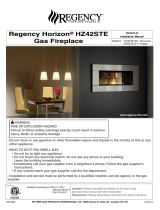
C72 FIREPLACE
Installation Reference Guide
REFER TO OWNER’S MANUAL FOR SPECIFIC INSTALLATION REQUIREMENTS AND ADDITIONAL PRODUCT INSTRUCTIONS
Clearance to Combustibles
A - Finishing edge to side wall 7" 229 mm
B - Minimum clearance to enclosure ceiling 84" 2134 mm
C - Minimum clearance to mantel height See Chart See Chart
D - Front of door to edge of floor protection 0" 0 mm
E - Minimum alcove width 88" 2235 mm
D
B
C
E
A
Minimum
Framing Dimensions
C-16874
WOOD STUD ROUGH OPENING
43.5”
(1105mm)
84”
(2134mm)
20”
(508mm)
38”
(965mm)
83”
(2108mm)
SUPPLIED STEEL STUD
1” (25mm)
Clearance from
framing studs
to venting
Depth 20” 508 mm
Width 83” 2108 mm
Header Height 38” 965 mm
Rough Opening Height 43.5” 1105mm
Enclosure Ceiling 84” 2134 mm
Note: Vent size = Co-axial 5 x 8”

56 1/2”
19”
10”
COMBUSTIBLE
NON COMBUSTIBLE
Framing
MetalStud
Drywall
Concrete
Board
Sidewall
7”
5 3/16
84
1 2 3 4 5 6 7 8 9 10 11 12 13 14
MANTLE HEIGHT
MANTLE DEPTH
Minimum Mantle Clearances
8” MANTLE
4”MANTLE
47
46
45
44”
43”
42”
41”
39”
40”
12” MANTLE
84"
2134mm
20"
508mm
671
2
"
1714mm
19"
483mm
Center of Thimble
Use one 24" and one 6"
to achieve minimum
rise in order for this
dimension to work.
Non-combustible
Zone
Non-Combustible Board
Placement
Mantel Projections
Mantel graph dimensions are measured from the bottom of the
replace, if you wish to reference the mantel height from the tiling
edge subtract 15 inches (381mm) from the mantel height depicted
on the graph. If you plan to install a TV above your replace refer to
the appropriate section of the owner’s manual for available options.
It is acceptable to install a combustible mantel over top of the non-
combustible board. If you are activating the Cool Surface System
you are eligible to subtract 12” (305mm) from the mantel height
shown in this diagram. See page 6 for more details.
Minimum Venting Requirements
Minimum permitted venting is shown below. The framing height
to the center of the thimble is 67.5”. Minimum venting must
include a 24” & 6” vertical section and a 90 degree elbow which
is then terminated horizontally. For a vertical termination please
follow the vent pipe manufacturer’s installation instructions for
vertical vent termination framing. A minimum of 1 in. (25 mm)
clearance on all sides of the vertical vent pipe must be maintained.
For every 12” of horizontal run there must be a 1/4” of rise. 1” of
clearance between framing and venting must be maintained at
all times. 2” above the venting and 3” above an elbow.
Fireplace Dimensions
82 3
4
"
2102mm
1
2
"
13mm
20"
507mm
9"
231mm
17 3
4
"
453mm
74"
1882mm
16"
404mm
31
4
"
81mm
7"
176mm
Gas Inlet
Bottom
(Optional)
4"
103mm
91
4
"
232mm
Gas Inlet
Right Side
91
4
"
232mm
3"
73mm
38"
965mm
Electrical
Inlet Left
Side
72"
1828mm
30 3
4
"
780mm
71
4
"
185mm
12 1
4
"
309mm
16 1
2
"
421mm
91
4
"
236mm
77"
1956mm

OPTIONAL STEP Cool Surface System Part 1
Dimensions
CSS Side Vent - Dimensions
8.00
6.17
8.42
14.39
0.88
2.63
7.47
11.74
6.07 4.65
10.72
7.67
0.50
12.18
14.92
1.39
12.24
13.64
36.00
4.75
4.75
4.75
9.95
26.00
36.00
9.75
2.48
.49
.49
2.48
4.75
.50
2.00
.92
.50
.50
36.00
4.75
4.75
4.75
9.95
26.00
36.00
9.75
2.48
.49
.49
2.48
4.75
.50
2.00
.92
.50
.50
36.00
4.75
4.75
4.75
9.95
26.00
36.00
9.75
2.48
.49
.49
2.48
4.75
.50
2.00
.92
.50
.50
36.00
4.75
4.75
4.75
9.95
26.00
36.00
9.75
2.48
.49
.49
2.48
4.75
.50
2.00
.92
.50
.50
36.00
4.75
4.75
4.75
9.95
26.00
36.00
9.75
2.48
.49
.49
2.48
4.75
.50
2.00
.92
.50
.50
36.00
4.75
4.75
4.75
9.95
26.00
36.00
9.75
2.48
.49
.49
2.48
4.75
.50
2.00
.92
.50
.50
C72 CSS Front Vent - Overall Dimensions
2 /”
2 /”
9 /”
11 /”
70 /”
75 /”
65 /”
7 /”
53”
Ø5” Vent Collars
3 /”
/” 2 /”
2”
7 /”
36.00
4.75
4.75
4.75
9.95
26.00
36.00
9.75
2.48
.49
.49
2.48
4.75
.50
2.00
.92
.50
.50
45.75
C72 CSS Combustible Facing Kit Dimensions

OPTIONAL STEP Cool Surface System Part 2
Framing & Rough Opening – Front Vent
CSS Outlet Min. Top and Bottom stando = 25/8” (6.7 cm) *All C Series*
7 1/2"
(2.5 cm)
C72 = 77 1/4" (196 cm)
2 x 4 (On Edge)
46 1/2"
(118 cm)
Min.
Height
C72 = 83" (211 cm)
Steel Stud
C72
*Steel Stud Required if not using Combustible Facing Kit*
Steel Stud
C72
Venting Clearances - Front Vent
Shown here are the minimum framing and clearances for
the CSS when the replace is installed with the minimum
allowable vent length:
Min. Ceiling Clearance from top of CSS outlet = 4” (10.2 cm)
Min. Ceiling Clearance in wall from top of CSS Body = 55/8” (14.3 cm)
CSS Body Min. Rear stando = 2¾” (69.8 cm)
5 5
8
" (14.3 cm)
4" (10.2 cm)
2 3
4
" (69.8 cm)
73 1
4
"
(174.9 cm)
Side Brace
Min. Height
20" (50.8 cm)
Min. Depth
39” (99 cm) Min.
Length 5” dia. ex vent
(not supplied)
80” (203 cm)
Minimum Ceiling
Min. Vent
91” (231 cm)
C72 Min. Ceiling
Outlet Finished Opening Size
71 1/8” (180.7 cm)
2 7/8” (7.3 cm)
3/8” (1.0 cm)
82 3/8”
(212 cm)
Side Brace
Min. Height

OPTIONAL STEP Cool Surface System Part 3
CSS Side Vent (Horizontal Install) - Min. Framing & Clearances
15.00” (38cm)
11.50”
(29cm)
Min. Height
to Ceiling
14.50
Min. Height
66.00”
(168cm)
Min. to
Ceiling
5” (12.5cm)
Min. Height
from oor
69.5” (176.5cm)
39” (99 cm) Min.
Length 5” dia. ex vent
(not supplied)
Min. Vent
Min. Distance to
wall from standoff
5.00” (13cm)
Min. Ceiling
Height
18.75”
(48cm)
*15.75” (40cm)
11.5” (29cm)
Min. Dist
61.75”
(157cm)
*NOTE: 15.75” from the
header is required for min.
ceiling height. Rest unit on
lower standoff. There will be
a 3/4“ (2cm) gap on from
the top standoff to the
header in this confirguration.
Min Framing is 15” x 11.5”
3/4” (2cm)
Gap Shown
Min. Distance
to Ceiling
4.5” (11.5cm)
Min. Distance
to oor
64” (162.5cm)
39” (99 cm) Min.
Length 5” dia.
ex vent
(not supplied)
Framing & Clearances – CSS Side Vent
Min. Height
51-3/8”
( 130cm)
C34 = 45” (114cm)
C44 = 55” (140cm)
C60 = 71” (180cm)
C72 = 83” (211cm)
CSS Side Vent (Vertical Install) - Min. Framing & Clearances
*Steel Stud Required if not using Combustible Facing Kit*
C72 = 83” (211 cm)
Min Height
60 1/4”
(153 cm)
Min Height
from oor
75” (191 cm)
Min Height
from oor
80” (203 cm)
Min Height
from oor
70 3/4” (180 cm) Min Height
from oor
73 3/4” (187 cm)

OPTIONAL STEP Cool Surface System Part 4
TV Installation Considerations:
29°F 41”
21°F 35”
21°F 29”
24°F 23”
17°F 17”
20°F 11”
30°F 5”
0”
Above
Ambient
Height from
Opening
4” Mantle
29” from oor.
Combustible
Facing Kit
1/2” Combustible Base
Material (Drywall)
Up to 1” Combustible
Material.
NOTE: You cannot install a Surround
with the mantle at its lowest position.
Install mantle at 31” for a Surround
Min.
2-1/2”
(6.4cm)
Min. 2” (5cm)
Gap
Combustible
Facing Kit
1/2” Combustible Base
Material (Drywall)
Up to 1” Combustible
Material
29°F 41”
29°F 35”
29°F 29”
27°F 23”
35°F 17”
38°F 11”
49°F 5”
0”
Above
Ambient
Height from
Opening
1-1/2” Air Gap behind the TV.
(Typically provided by a wall
mount)
TV must be 5” min from
discharge if no mantle
Min. 3/4” (1.9cm)
Mantel Thickness
29 “
(74cm)
31 “
(79cm)
Min. Height
For Surround
33“
(84cm)
4” (102mm)
8” (203mm)
12” (305mm)
2-1/16”
(75cm)
Min. Height
to Ceiling
55-1/16”
(1399cm)
Min. Height
to Ceiling
64 1/8”
(1630mm)
29 “
(74cm)
31 “
(79cm)
Min. Height
For Surround
33“
(84cm)
4” (102mm)
8” (203mm)
12” (305mm)
2-1/16”
(75cm)
Min. Height
to Ceiling
55-1/16”
(1399cm)
If you are planning to mount a TV above your
replace some considerations must be made to
ensure it is protected from the heat.
During testing temperatures did not exceed
121°F (49°C) midway up the front wall (see
gures on right). There is no guarantee that these
temperatures will not harm the longevity of your
TV. Make sure to consult your TV manufacturer’s
specications to nd the maximum allowable
operating temperature. Since every home and
installation is unique, temperatures should be veried
at the time of install if possible. If desired, front wall
temperatures can be lowered to 104°F (40°C) with the
use of a mantle (see CSS TV clearances with Mantle
gure). See revised mantle clearances chart above. A
TV should not be installed if temperatures exceed the
manufacturers maximum allowable temperature.
CSS - TV Clearances CSS - TV Clearances with Mantle
Framing & Revised Mantle
Clearances - Front Vent
Framing & Revised Mantle
Clearances - Side Vent
Min. Height
to Ceiling
64 1/8”
(1630mm)
/