Linksys NULL WPC55AG User manual
- Category
- Networking
- Type
- User manual
This manual is also suitable for

Dual-Band Wireless A+G
Notebook Adapter
Use this guide to install:
WPC55AG
User Guide

COPYRIGHT & TRADEMARKS
Specifications are subject to change without notice. Linksys is a registered trademark or
trademark of Cisco Systems, Inc. and/or its affiliates in the U.S. and certain other coun-
tries. Copyright © 2003 Cisco Systems, Inc. All rights reserved. Other brands and prod-
uct names are trademarks or registered trademarks of their respective holders.
LIMITED WARRANTY
Linksys warrants to the original end user purchaser ("You") that, for a period of three
years. Your Linksys product will be free of defects in materials and workmanship under
normal use. Your exclusive remedy and Linksys's entire liability under this warranty will
be for Linksys at its option to repair or replace the product or refund Your purchase price
less any rebates.
If the product proves defective during the Warranty Period call Linksys Technical Support
in order to obtain a Return Authorization Number. BE SURE TO HAVE YOUR PROOF OF
PURCHASE ON HAND WHEN CALLING. When returning a product, mark the Return
Authorization Number clearly on the outside of the package and include a copy of your
original proof of purchase. RETURN REQUESTS CANNOT BE PROCESSED WITHOUT
PROOF OF PURCHASE. You are responsible for shipping defective products to Linksys.
Linksys pays for UPS Ground shipping from Linksys back to You only. Customers locat-
ed outside of the United States of America and Canada are responsible for all shipping
and handling charges.
ALL IMPLIED WARRANTIES AND CONDITIONS OF MERCHANTABILITY OR FITNESS
FOR A PARTICULAR PURPOSE ARE LIMITED TO THE DURATION OF THE WARRANTY
PERIOD. ALL OTHER EXPRESS OR IMPLIED CONDITIONS, REPRESENTATIONS AND
WARRANTIES, INCLUDING ANY IMPLIED WARRANTY OF NON-INFRINGEMENT, ARE
DISCLAIMED. Some jurisdictions do not allow limitations on how long an implied war-
ranty lasts, so the above limitation may not apply to You. This warranty gives You spe-
cific legal rights, and You may also have other rights which vary by jurisdiction.
TO THE EXTENT NOT PROHIBITED BY LAW, IN NO EVENT WILL LINKSYS BE LIABLE
FOR ANY LOST DATA, REVENUE OR PROFIT, OR FOR SPECIAL, INDIRECT, CONSE-
QUENTIAL, INCIDENTAL OR PUNITIVE DAMAGES, HOWEVER CAUSED REGARDLESS
OF THE THEORY OF LIABILITY, ARISING OUT OF OR RELATED TO THE USE OF OR
INABILITY TO USE THE PRODUCT, EVEN IF LINKSYS HAS BEEN ADVISED OF THE
POSSIBILITY OF SUCH DAMAGES. IN NO EVENT WILL LINKSYS' LIABILITY EXCEED
THE AMOUNT PAID BY YOU FOR THE PRODUCT.
The foregoing limitations will apply even if any warranty or remedy provided under this
Section fails of its essential purpose. Some jurisdictions do not allow the exclusion or lim-
itation of incidental or consequential damages, so the above limitation or exclusion may
not apply to You.
Please direct all inquiries to: Linksys, P.O. Box 18558, Irvine, CA 92623.
SAFETY AND REGULATORY NOTICES
FCC STATEMENT
The Dual-Band Wireless A+G Notebook Adapter has been tested and found to comply
with the specifications for a Class B digital device, pursuant to Part 15 of the FCC Rules.
Operation is subject to the following two conditions:
(1) This device may not cause harmful interference, and
(2) This device must accept any interference received, including interference that may
cause undesired operation.
These limits are designed to provide reasonable protection against harmful interference
in a residential installation. This equipment generates, uses, and can radiate radio fre-
quency energy and, if not installed and used according to the instructions, may cause
harmful interference to radio communications. However, there is no guarantee that inter-
ference will not occur in a particular installation. If this equipment does cause harmful
interference to radio or television reception, which is found by turning the equipment off
and on, the user is encouraged to try to correct the interference by one or more of the
following measures:
• Reorient or relocate the receiving antenna
• Increase the separation between the equipment or devices
• Connect the equipment to an outlet other than the receiver's
• Consult a dealer or an experienced radio/TV technician for assistance
FCC Caution: Any change or modification to the product not expressly approved by
Linksys could void the user's authority to operate the device.
FCC Caution: Operation within the 5150 to 5250GHz band is restricted to indoor use only.
FCC RF Radiation Exposure Statement
To comply with the FCC and ANSI C95.1 RF exposure limits, the antenna(s) for this
device must comply with the following:
• Access points with 2.4 GHz or 5 GHz integrated antenna must operate with a sepa-
ration distance of at least 20 cm from all persons using the cable provided and must
not be co-located or operating in conjunction with any other antenna or transmitter.
End-users must be provided with specific operations for satisfying RF exposure compli-
ance.
Note: Dual antennas used for diversity operation are not considered co-located.
INDUSTRY CANADA (CANADA)
This Class B digital apparatus complies with Canadian ICES-003.
Cet appareil numérique de la classe B est conforme à la norme NMB-003 du Canada.
The use of this device in a system operating either partially or completely outdoors may
require the user to obtain a license for the system according to the Canadian regulations.
EC DECLARATION OF CONFORMITY (EUROPE)
Linksys Group declares that the products included conform to the specifications listed
below, following the provisions of the European R&TTE directive 1999/5/EC, EMC direc-
tive 89/336/EEC, and Low Voltage directive 73/23/EEC:
For 11Mbps, 2.4 GHz devices with 100 mW radios, the following standards were applied:
• ETS 300-826, 301 489-1 General EMC requirements for Radio equipment.
• EN 609 50 Safety
• ETS 300-328-2 Technical requirements for Radio equipment.
For 54Mbps, 5 GHz devices with 40 mW radios, the following standards were applied:
• ETS 301 489-1, 301 489-17 General EMC requirements for Radio equipment.
• EN 609 50 Safety
• ETS 301-893 Technical requirements for Radio equipment.
Caution: The frequencies used by 802.11a wireless LAN devices are not yet harmonized
within the European community, 802.11a products are designed for use only in specific
countries, and are not allowed to be operated in countries other than those of designat-
ed use. Contact local Authority for procedure to follow.
Caution: This equipment is intended to be used in all EU and EFTA countries. Outdoor
use may be restricted to certain frequencies and/or may require a license for operation.
Contact local Authority for procedure to follow.

Table of Contents
Chapter 1: Introduction 1
The Dual-Band Wireless A+G Notebook Adapter 1
Features 1
Chapter 2: Planning Your Wireless Network 2
Network Topology 2
Ad-Hoc versus Infrastructure Mode 2
Chapter 3: The Dual-Band Wireless A+G Notebook
Adapter’s LEDs 4
Chapter 4: Installation and Configuration
for Windows XP 5
Overview 5
Hardware Installation 5
Driver Installation for Windows XP 6
Windows XP Wireless Zero Configuration 7
Chapter 5: Installation and Configuration
for Windows 98, Me, and 2000 9
Overview 9
Software Installation for Windows 98, Me, and 2000 9
Hardware Installation 14
Note: Combinations of power levels and antennas resulting in a radiated power level of
above 100 mW equivalent isotropic radiated power (EIRP) are considered as not com-
pliant with the above mentioned directive and are not allowed for use within the European
community and countries that have adopted the European R&TTE directive 1999/5/EC
and/or the CEPT recommendation Rec 70.03.
For more details on legal combinations of power levels and antennas, contact Linksys
Corporate Compliance.
• Linksys Group vakuuttaa täten että Dual-Band Wireless A+G Notebook Adapter tyyp-
pinen laite on direktiivin 1999/5/EY, direktiivin 89/336/EEC ja direktiivin 73/23/EEC
oleellisten vaatimusten ja sitä koskevien näiden direktiivien muiden ehtojen
mukainen.
• Linksys Group déclare que la Dual-Band Wireless A+G Notebook Adapter est con-
forme aux conditions essentielles et aux dispositions relatives à la directive
1999/5/EC, la directive 89/336/EEC, et à la directive 73/23/EEC.
• Belgique B L'utilisation en extérieur est autorisé sur le canal 11 (2462 MHz), 12 (2467
MHz), et 13 (2472 MHz). Dans le cas d'une utilisation privée, à l'extérieur d'un bâti-
ment, au-dessus d'un espace public, aucun enregistrement n'est nécessaire pour
une distance de moins de 300m. Pour une distance supérieure à 300m un enreg-
istrement auprès de l'IBPT est requise. Pour une utilisation publique à l'extérieur de
bâtiments, une licence de l'IBPT est requise. Pour les enregistrements et licences,
veuillez contacter l'IBPT.
• France F:
2.4 GHz Bande : les canaux 10, 11, 12, 13 (2457, 2462, 2467, et 2472 MHz respec-
tivement) sont complétement libres d'utilisation en France (en utilisation intérieur).
Pour ce qui est des autres canaux, ils peuvent être soumis à autorisation selon le
départment. L'utilisation en extérieur est soumis à autorisation préalable et très
restreint.
5 GHz Bande: Conformément aux décisions de la CEPT, l'utilisation des fréquences
de la bande 5150 MHz - 5350 MHz est autorisée à l'intérieur des bâtiments avec une
puissance maximale de 200 mW, et interdite en extérieur. La bande 5470 MHz - 5725
MHz n'est pas ouverte aujourd'hui.
Vous pouvez contacter l'Autorité de Régulation des Télécommunications
(http://www.art-telecom.fr) pour de plus amples renseignements.
2.4 GHz Band: only channels 10, 11, 12, 13 (2457, 2462, 2467, and 2472 MHz
respectively) may be used freely in France for indoor use. License required for out-
door installations.
5 GHz Band: frequencies in the 5150 MHz - 5350 MHz band may be used indoor
with maximum power of 200 mW. Their use is forbidden outdoors. The 5470 MHz -
5725 MHz band is not currently open.
Please contact ART (http://www.art-telecom.fr) for procedure to follow.
• Deutschland D: Anmeldung im Outdoor-Bereich notwending, aber nicht genehmi-
gungspflichtig. Bitte mit Händler die Vorgehensweise abstimmen.
• Germany D: License required for outdoor installations. Check with reseller for proce-
dure to follow.
• Italia I: E' necessaria la concessione ministeriale anche per l'uso interno. Verificare
con i rivenditori la procedura da seguire. L'uso per installazione in esterni non e' per-
messa.
• Italy I: License required for indoor use. Use with outdoor installations not allowed.
• The Netherlands NL License required for outdoor installations. Check with reseller for
procedure to follow.
• Nederlands NL Licentie verplicht voor gebruik met buitenantennes. Neem contact op
met verkoper voor juiste procedure.
WPC55AG-UG-30806C KL

Chapter 1: Introduction
The Linksys Dual-Band Wireless A+G Notebook Adapter lets your notebook
communicate with all three wireless network standards. With one PC Card, you
can connect to Wireless-A (802.11a), Wireless-G (draft 802.11g) and Wireless-
B (802.11b) networks.
Wireless-B networks have a data rate of 11Mbps, and are commonly found in
corporate environments and in homes for household Internet connectivity with-
out the need for running cables. They’re also popping up all over the country in
coffee shops, airports, hotels, convention centers, and other public spaces offer-
ing “on the go” connectivity to mobile users.
In high speed or heavy usage environments, Wireless-B is quickly being
replaced by a new standard, Wireless-G, which uses the same 2.4GHz radio
band, but at 54Mbps, is almost five times faster. The third wireless network
standard is Wireless-A, which also runs at 54Mbps, but operates in the less-
crowded 5GHz radio band. Wireless-A is mostly used in corporate installa-
tions.
Whichever standard you encounter, the Dual-Band Wireless A+G Notebook
Adapter is ready to connect. And it’s simple to use. Just pop it into a PC Card
slot and run the included Setup Wizard which will walk you through the con-
figuration. All wireless communications can be protected by up to 152-bit
encryption, so your data stays secure.
Join the wireless revolution. With the Linksys Dual-Band Wireless A+G
Notebook Adapter, you’ll be ready to connect to all three types of wireless net-
works, wherever you go, now and in the future.
• Connects to either 2.4Ghz (802.11b or draft 802.11g) or 5Ghz (802.11a)
networks without changing adapters
• Advanced security features with LEAP and up to 152-Bit WEP encryption
• Easy-to-use Setup Wizard
• Detailed monitoring and performance utility
• 802.11a, 802.11b and draft 802.11g compliant
• 32-Bit CardBus Interface
• Cisco Compatible Extensions
The Dual-Band Wireless A+G Notebook Adapter
Features
1
Chapter 6: Using the WLAN Monitor for
Windows 98, Me, and 2000 15
Overview 15
Starting the WLAN Monitor 15
Link Information 16
Site Survey 18
Profiles 20
Creating a New Profile 22
Appendix A: Troubleshooting 30
Common Problems and Solutions 30
Frequently Asked Questions 31
Appendix B: Glossary 34
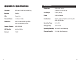
Appendix C: Specifications 42
Environmental 43
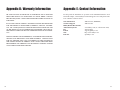
Appendix D: Warranty Information 44
Appendix E: Contact Information 45

If the wireless network is relatively small and needs to share resources only
with the other computers on the wireless network, then the ad-hoc mode can
be used. (See Figure 2-2.) Ad-hoc mode allows computers equipped with wire-
less transmitters and receivers to communicate directly with each other, elimi-
nating the need for an access point. The drawback of this mode is that, in Ad-
Hoc mode, wireless-equipped computers are not able to communicate with
computers on a wired network. And, of course, communication between the
wireless-equipped computers is limited by the distance and interference direct-
ly between them.
32
Figure 2-2
Chapter 2: Planning Your Wireless
Network
A wireless local area network (WLAN) is exactly like a regular local area net-
work (LAN), except that each computer in the WLAN uses a wireless device to
connect to the network. Computers in a WLAN share the same frequency chan-
nel and SSID, which is an identification name for wireless devices.
Unlike wired networks, wireless networks have two different modes in which
they may be set up: infrastructure and ad-hoc. An infrastructure configura-
tion is a WLAN and wired LAN communicating to each other through an
access point. An ad-hoc configuration is wireless-equipped computers com-
municating directly with each other. Choosing between these two modes
depends on whether or not the wireless network needs to share data or periph-
erals with a wired network or not.
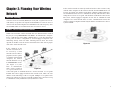
If the computers on the
wireless network need to
be accessed by a wired
network or need to share a
peripheral, such as a print-
er, with the wired network
computers, the wireless
network should be set up
in infrastructure mode.
(See Figure 2-1.) The
basis of infrastructure
mode centers around an
access point, which serves
as the main point of communications in a wireless network. Access points
transmit data to PCs equipped with wireless network cards, which can roam
within a certain radial range of the access point. Multiple access points can be
arranged to work in succession to extend the roaming range, and can be set up
to communicate with your Ethernet (wired) hardware as well.
Network Topology
Ad-Hoc versus Infrastructure Mode
Figure 2-1

54
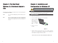
Chapter 3: The Dual-Band
Wireless A+G Notebook Adapter’s
LEDs
The Adapter has two LEDs to let you know how the card is functioning. Here
is a description of those LEDs:
Power Green. The Power LED lights up when the Adapter is pow-
ered on.
Link Green. The Link LED lights up and stays solid when the
Adapter is inserted correctly and a link is established with
the notebook. The LED flashes when data is transmitted or
received.
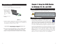
Chapter 4: Installation and
Configuration for Windows XP
After installing the Dual-Band Wireless A+G Notebook Adapter in your com-
puter, you will install the driver and configure the Adapter.
1. Turn off your notebook PC.
2. Locate an available CardBus slot on your notebook PC.
3. With the Adapter’s
label facing up, as
shown in Figure 4-1,
slide it completely
into the CardBus
slot.
4. Restart your note-
book PC.
5. Windows will begin copying the driver files to your computer. If Windows
asks you for the original Windows CD-ROM, insert the CD-ROM, and
direct Windows to its proper location (e.g., D:\).
Proceed to the next section, “Driver Installation for Windows XP.”
Important for Windows 98, Me, and 2000 users: Go to “Chapter 5:
Installation and Configuration for Windows 98, Me, and 2000.”
Figure 4-1
Overview
Hardware Installation

7
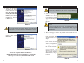
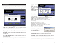
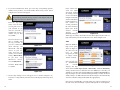
1. After installing the
Adapter, the Windows
XP Wireless Zero
Configuration icon will
appear in your computer’s
system tray. Double-click
the icon.
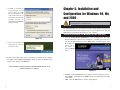
2. The screen that appears will show any available wireless network. Select the
network you want.
If this network has WEP
encryption disabled, go to
Step 3.
If this network does not
have WEP encryption
enabled, then Figure 4-6
will appear. Make sure
the box next to Allow me
to connect to the selected
wireless network, even
though it is not secure is
checked. Then click the
Connect button, and go
to Step 4.
Windows XP Wireless Zero Configuration
Important for Windows XP users: Windows XP has a built-in con-
figuration tool. Use the Windows XP Wireless Zero Configuration (in
the system tray at the bottom of your screen) to configure the Adapter.
Figure 4-5
Note: These instructions are for Windows XP with Service Pack 1
installed.
If you have not installed Service Pack 1, select the network you want,
and click the Connect button. If the network has WEP encryption
enabled, enter the WEP key in the Network key field, and then click the
Connect button.
Figure 4-6
6
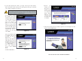
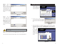
1. Windows XP will automati-
cally detect the Adapter.
Click the radio button next to
Install the software auto-
matically (Recommended).
Insert the Setup Wizard CD-
ROM into your computer’s
CD-ROM drive. Then click
the Next button.
2. After Windows has finished
installing the driver, click the
Finish button.
You have now completed the driver installation for
the Dual-Band Wireless A+G Notebook Adapter. To configure the
Adapter, proceed to the next section, “Windows XP Wireless
Zero Configuration.”
Important for Windows XP users: Do NOT run the Dual-Band
Wireless A+G Notebook Adapter Setup Wizard. If the Setup Wizard
runs automatically after the Setup Wizard CD-ROM has been insert-
ed, click the Exit tab.
Figure 4-3
Driver Installation for Windows XP
Figure 4-4

9
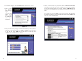
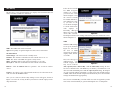
3. If WEP is enabled, the
screen in Figure 4-7 will
appear. Enter the WEP
key of your wireless net-
work in the Network key
field, and re-enter it in the
Confirm network key
field. Then click Connect,
and go to Step 4.
4. The screen in Figure 4-8
will appear if your con-
nection is active.
For more information about wireless networking on a Windows XP computer,
click Start and then Help and Support. Enter the keyword wireless in the
field provided, and press the Enter key.
Congratulations! The installation of the Dual-Band Wireless A+G
Notebook Adapter is complete.
8
Chapter 5: Installation and
Configuration for Windows 98, Me,
and 2000
The Dual-Band Wireless A+G Notebook Adapter Setup Wizard will guide you
through the installation and configuration procedure for Windows 98, Me, and
2000. Then you will install the Adapter in your computer.
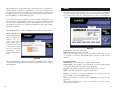
1. Insert the Setup Wizard CD-ROM into your CD-ROM drive. The Setup
Wizard should run automatically, and Figure 5-1 should appear. If it does
not, click the Start button and choose Run. In the field that appears, enter
D:\setup.exe
(where “D” is
the letter of
your CD-ROM
drive).
• Install - Click the Install button to begin the software installation process.
• User Guide - Clicking the User Guide button opened this PDF file of this
User Guide.
• Exit - Click the Exit button to exit the Setup Wizard.
Figure 5-1
Important for Windows XP users: Go to “Chapter 4: Installation
and Configuration for Windows XP.”
Overview
Software Installation for Windows 98, Me, and 2000
Figure 4-7
Figure 4-8

1110
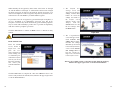
5. Choose a wireless mode for your network. Click the Infrastructure Mode
radio button if you want your wireless computers to network with computers
on your wired network using an access point. Click the Ad-Hoc Mode radio
button if you want multiple wireless computers to network directly with each
other.
In the SSID field, enter the SSID of your wireless network. The SSID must
be identical for all devices in the network. The default setting is linksys (all
lowercase). Click the Next button.
Figure 5-4
2. To install the Adapter, click the Install button on the Welcome screen.
3. After reading
the Warranty
Policy, shown in
Figure 5-2,
click the Next
button if you
agree, or click
the Cancel but-
ton to end the
installation.
4. Next you will choose your type of wireless network. If you will connect to
both 802.11a and 54g networks, select 5GHz + 2.4GHz. If you will connect
to only 802.11a, select 5GHz. If you will connect to only 54g, select
2.4GHz. Click the Next button to continue.
Figure 5-2
Figure 5-3

1312
7. Review your
settings on the
Finalize
Settings screen,
shown in Figure
5-7, before the
Setup Wizard
starts to copy
your files. Click
the Next button
to continue.
8. After the files have been successfully copied, the screen in Figure 5-8 will
appear. Click the Exit button.
Proceed to the next section, “Hardware Installation.”
Figure 5-8
Figure 5-7
6. If you chose Infrastructure Mode, go to Step 7 now. If you chose Ad-Hoc
Mode, the Ad-Hoc Mode Setting screen will appear for the type of network
you’re using (see Figures 5-5 and 5-6).
For the Channel setting,
the channel you choose
should match the channel
set on the other devices in
your wireless network.
Select the channel you
plan to use for your
802.11a or 54g network
from the appropriate drop-
down screen that appears.
If you want the network to
automatically choose a
channel for you, then
select Auto.
The Network Mode setting
is available only for 54g
networks. If you have
Wireless-G (draft
802.11g) and Wireless-B
(802.11b) devices in your
network, then keep the
default Network Mode set-
ting, Mixed Mode. If you
have only Wireless-G
devices, select G-Only
Mode.
Click the Next button.
Figure 5-5
Note: If you chose 5GHz + 2.4GHz in Step 4 for connection to both
802.11a and 54g networks, then go to Step 6. The Adapter will auto-
matically select the best channel for you.
Figure 5-6

1514
Chapter 6: Using the WLAN Monitor
for Windows 98, Me, and 2000
Use the WLAN Monitor to check the link information, search for available
wireless networks, or make additional configuration changes.
After installing the Adapter, the Dual-Band Wireless A+G
Notebook Adapter WLAN Monitor icon (see Figure 6-1) will
appear in the system tray, which is located at the bottom right-hand
corner of your screen. The top left-hand corner of the icon will
light up blue if the Adapter is installed and active. Its bottom right-
hand corner will light up yellow if the Adapter is connected to a wireless
screen. The icon will remain dim if the Adapter is not installed or is disabled.
Double-click the WLAN Monitor icon, and the Link Information screen will
appear. From this screen, you can find out how strong the Adapter’s wireless
signal is and how good the connection’s quality is. Click the More
Information button to view additional status information about the current
wireless connection. To search for available wireless networks, click the Site
Survey tab. To perform configuration changes, click the Profiles tab.
Figure 6-1
Important for Windows XP users: Windows XP has a built-in
configuration tool. Use the Windows XP Wireless Zero Configuration (in
the system tray at the bottom of your screen) to configure the Adapter.
See “Chapter 4: Installation and Configuration for Windows XP.”
Starting the WLAN Monitor
Overview
1. Turn off your notebook PC.
2. Locate an available CardBus slot on your notebook PC.
3. With the Adapter’s
label facing up, as
shown in Figure 5-9,
slide it completely
into the CardBus
slot.
4. Restart your note-
book PC.
5. Windows will begin copying the driver files to your computer. If Windows
asks you for the original Windows CD-ROM, insert the CD-ROM, and
direct Windows to its proper location (e.g., D:\).
Congratulations! The installation of the Dual-Band Wireless A+G
Notebook Adapter is complete.
If you want to check the link information, search for available wireless
networks, or make additional configuration changes, proceed to
“Chapter 6: Using the WLAN Monitor for Windows 98, Me, and 2000.”
Figure 5-9
Hardware Installation

17
The Link Information screen, shown in Figure 6-2, displays the Adapter’s sig-
nal strength and link quality information. Click the More information button
for further information about your wireless connection (see Figure 6-3).
Ad-Hoc Mode or Infrastructure Mode - The screen indicates whether the
Adapter is currently working in ad-hoc or infrastructure mode.
Signal Strength - The Signal Strength bar indicates the strength of the
Adapter’s signal.
Link Quality - The Link Quality bar indicates the quality of the wireless net-
work connection.
Click the More Information button to view more information about the wire-
less network connection.
Click the X (Close) button in the upper right corner to exit the WLAN Monitor.
16
Wireless Network
Status
Status- The status of
the wireless network
connection.
SSID - The SSID of the
wireless network.
Network Mode - The
wireless mode current-
ly in use, ad-hoc or
infrastructure.
Transfer Rate - The
data transfer rate of the
current connection.
Channel - The channel to which the wireless network devices are set.
WEP - The status of the WEP encryption security feature.
MAC - The MAC address of the wireless network’s access point.
TCP/IP Setting
IP Address - The IP Address of the Adapter.
Subnet Mask - The Subnet Mask of the Adapter.
Default Gateway - The Default Gateway address of the Adapter.
DNS - The DNS address of the Adapter.
DHCP - The status of the DHCP client.
Click the Save to Profile button to save
the current settings in a profile. Enter a
name for the profile (see Figure 6-4), and
then click the OK button.
Signal Strength - This indicates the strength of the Adapter’s signal.
Link Quality - This indicates the quality of the wireless network connection.
Click the Back button to return to the initial Link Information screen.
Click the X (Close) button in the upper right corner to exit the WLAN Monitor.
Figure 6-3
Figure 6-4
Link Information
Figure 6-2

If the wireless network
has WEP encryption
enabled for security,
you will see the screen
shown in Figure 6-6. If
the wireless network
has LEAP authentica-
tion enabled for securi-
ty, you will see the
screen shown in Figure
6-7. If the wireless net-
work employs an
Externally Managed
802.1x type of security,
choose this selection.
The Adapter will detect the settings and forward you to the next Profile screen,
shown in Figure 6-9.
WEP
When the WEP settings
screen opens, shown in
Figure 6-7, first select
the level of WEP
encryption you wish to
employ: 64-bit, 128-bit,
or 152-bit.
Next, select the type of
Authentication your
network employs. You
may choose between
Auto, Open System or Shared Key. With the Shared Key setting, all wire-
less devices must have the same WEP keys so that they can authenticate each
other and start transmitting data. With the Open System setting, the Adapter
can join a network without performing a security check. The default setting is
to Auto, which means that the Adapter will automatically detect the network’s
settings and transmit data appropriately.
Next, choose a Transmit Key, 1-4. This will be one of the encryption keys in the
four fields, entered manually or generated through the use of a Passphrase.
1918
The Site Survey screen, shown in Figure 6-5, displays a list of infrastructure and
ad-hoc networks available for connection.
SSID - The SSID of the wireless network.
Signal - The quality of signal strength: Poor, Fair, Good, or Excellent.
Site Information
Network Type - The wireless mode currently in use.
Channel - The channel to which the wireless network devices are set.
WEP - The status of the WEP encryption security feature.
MAC - The MAC address of the wireless network’s access point.
Surveyed at - The time at which the wireless network was scanned.
Refresh - Click the Refresh button to perform a new search for wireless
devices.
Connect - To connect to one of the networks on the list, select the wireless net-
work, and click the Connect button.
Once you are connected, the Security Settings screen will appear, shown in
Figure 6-6. Select the security method your wireless network employs in the
drop-down menu.
Figure 6-5
Site Survey
Figure 6-6
Figure 6-7

21
When manually, the encryption key must consist of the letters “A” through “F”
and the numbers “0” through “9” and should be 10 characters in length for 64-
bit encryption, 26 characters in length for 128-bit encryption, or 32 characters
in length for 152-bit encryption.) All points in your wireless network must use
the same WEP key to utilize WEP encryption.
If you wish to have the encryption key generated through a Passphrase, it can
be a maximum of 16 alphanumeric characters. Type this in the Passphrase field
and a key will be automatically generated. This passphrase may not work with
non-Linksys products due to possible incompatibility with other vendors’
passphrase generators.
Click the Next button to continue or Back to chose a different security method.
LEAP Authentication
From the LEAP screen,
shown in Figure 6-8,
complete the User
Name and Password
fields, making sure to
confirm the password
in the Confirm field. If
you do not know this
information, contact
your network adminis-
trator.
Click the Next button to complete the connection or Back to chose a different
security method. Click the X (Close) button in the upper right corner to exit the
WLAN Monitor.
20
The Profiles screen, shown in Figure 6-9, lets you save different configuration
profiles for different network setups. You can also import or export profiles.
The default profile holds the configuration saved when you installed the
Adapter.
Profile Name - The name of the profile.
SSID - The SSID of the wireless network.
Type - This letter signifies the type of network assigned to this profile. The let-
ter A signifies an 802.11a network, B signifies 802.11b, and G signifies
802.11g.
Profile Information
Network Type - The network mode: Ad-Hoc or Infrastructure.
Transfer Rate - The Adapter is set to Auto mode, so it will dynamically shift
to the fastest data transfer rate possible at any given time.
Channel - The channel to which the wireless network devices are set.
WEP - The status of the WEP encryption security feature.
Connect - To connect to a wireless network using a specific profile, select the
profile’s SSID, and click the Connect button.
Edit - Select the profile’s name, and click the Edit button to change an exist-
ing profile.
New - Click the New button to create a new profile. See the next section,
“Creating a New Profile.”
Figure 6-9
Profiles
Figure 6-8

23
Import - Click the
Import button to
import a profile that
has been saved in
another location. Select
the appropriate file, as
shown in Figure 6-10,
and click the Open
button.
Export - Select the
profile you want to
save in a different loca-
tion, and click the
Export button. Select
the appropriate folder,
as shown in Figure 6-
11, and click the Save
button.
Delete - Select a profile, then click the Delete button to delete a profile.
Click the X (Close) button in the upper right corner to exit the WLAN Monitor.
22
1. On the Profiles screen,
shown in Figure 6-12,
click the New button to
create a new profile.
2. On the Create connection profile
screen, shown in Figure 6-13, enter the
Profile’s name. Then click the OK but-
ton.
3. The Profile Wizard screen (Figure 6-14) appears next. Select one of three
wireless network types. Select the 2.4GHz + 5 GHz if you will connect to
both 802.11a and 54g networks. Select 5GHz if you will only connect to
802.11a net-
works. Select
the 2.4 GHz if
you will only
connect to 54g
networks. Then
click the Next
button.
Creating a New Profile
Figure 6-12
Figure 6-14
Figure 6-13
Figure 6-10
Figure 6-11
Note: If you want to export more than one profile, you have to export
them one at a time.

2524
5. The Choose a network type screen (Figure 6-16) shows a choice of two net-
work modes. Click the Infrastructure Mode radio button if you want your
wireless computers to communicate with computers on your wired network
via an access point. Click the Ad-Hoc Mode radio button if you want mul-
tiple wireless computers to communicate directly with each other. Then,
enter the SSID for your wireless network in the SSID 1 field. Enter alter-
native SSIDs in the SSID 2 and SSID 3 fields. Click the Next button.
Infrastructure Mode - This mode allows wireless and wired networks to
communicate through an access point.
Ad-Hoc Mode - This mode allows wireless-equipped computers to com-
municate directly with each other. No access point is used.
SSID - The SSID is the unique name shared by all devices in a wireless
network. The SSID must be identical for all devices in the wireless network.
It is case-sensitive and must not exceed 32 characters (use any of the char-
acters on the keyboard). Make sure this setting is the same for all devices in
your wireless network.
When attempting a connection, the Adapter will try SSID 1. If unsuccess-
ful, the Adapter will then try SSID 2 and SSID 3 until a connection is made.
Figure 6-16
4. The Network Settings screen, shown in Figure 6-15, will appear.
If your network has a DHCP server, click the radio button next to Obtain
an IP address automatically (DHCP). Click the Next button to continue,
and go to step 4.
If your network does not have a DHCP server, click the radio button next to
Specify the IP address. Enter an IP Address, Subnet Mask, Default
Gateway, and DNS appropriate for your network. You must specify the IP
Address and Subnet Mask on this screen. If you are unsure about the
Default Gateway and DNS addresses, then leave these fields alone.
Click the Next button to continue, and go to Step 4.
IP Address - This IP Address must be unique to your network.
Subnet Mask - The Adapter’s Subnet Mask must be the same as your wired
network’s Subnet Mask.
Default Gateway - Enter the IP address of your network’s Gateway.
DNS - Enter the DNS server addresses used by your ISP.
Figure 6-15

If the wireless net-
work has WEP
encryption enabled
for security, you will
see the screen shown
in Figure 6-20. If the
wireless network has
LEAP authentica-
tion enabled for
security, you will see
the screen shown in
Figure 6-21. If the
wireless network
employs an
Externally Managed
802.1x type of security, choose this selection. The Adapter will detect the set-
tings and forward you to the next Profile screen, shown in Figure 6-22.
WEP
When the WEP set-
tings screen opens,
shown in Figure 6-
20, first select the
level of WEP
encryption you wish
to employ: 64-bit,
128-bit, or 152-bit.
Next, select the type
of Authentication
your network
employs. You may
choose between Auto, Open System or Shared Key. With the Shared Key
setting, all wireless devices must have the same WEP keys so that they can
authenticate each other and start transmitting data. With the Open System set-
ting, the Adapter can join a network without performing a security check. The
default setting is to Auto, which means that the Adapter will automatically
detect the network’s settings and transmit data appropriately.
Next, choose a Transmit Key, 1-4. This will be one of the encryption keys in
the four fields, entered manually or generated through the use of a Passphrase.
2726
6. If you chose Infrastructure mode, proceed to Step 6. Depending upon the
Ad-Hoc mode you chose, one or both Ad-Hoc Mode Setting screens, shown
in Figure 6-17 and 6-18, will appear.
From the drop-down
menu, select the chan-
nel you plan to use for
your network. If you
want the network to
automatically choose a
channel for you, then
select Auto.
The Network Mode set-
ting is available only
for 54g networks. If
you have Wireless-G
(draft 802.11g) and
Wireless-B (802.11b)
devices in your net-
work, then keep the
default Network Mode
setting, Mixed Mode.
If you have only
Wireless-G devices,
select G-Only Mode.
Click the Next button
to continue.
7. The Security Settings screen will appear next, as shown in Figure 6-19.
Select the security method your wireless network employs in the drop-down
menu.
Figure 6-17
Note: If you chose 5GHz + 2.4GHz in Step 2 for connection to both
802.11a and 54g networks, then go to Step 6. The Adapter will auto-
matically select the best channel for you.
Figure 6-18
Figure 6-19
Figure 6-20

29
8. The Confirm New
Settings screen will
appear. To save the new
settings, click the Save
button. To cancel the
settings and return to
the Profiles screen
without saving your
changes, click the
Cancel button. To edit
the new settings, click
the Back button.
9. The Congratulations
screen will appear next.
Click Activate new
settings now to imple-
ment the new settings
immediately and return
to the Link Information
screen. Click Activate
new settings later to
keep the current set-
tings active and return
to the Profiles screen.
You have successfully created a connection profile. Click the X (Close)
button in the upper right corner to exit the WLAN Monitor.
Figure 6-23
Figure 6-22
When manually, the encryption key must consist of the letters “A” through
“F” and the numbers “0” through “9” and should be 10 characters in length
for 64-bit encryption, 26 characters in length for 128-bit encryption, or 32
characters in length for 152-bit encryption.) All points in your wireless net-
work must use the same WEP key to utilize WEP encryption.
If you wish to have the encryption key generated through a Passphrase, it
can be a maximum of 16 alphanumeric characters. Type this in the
Passphrase field and a key will be automatically generated. This passphrase
may not work with non-Linksys products due to possible incompatibility
with other vendors’ passphrase generators.
Click the Next button to continue or Back to chose a different security
method.
LEAP Authentication
From the LEAP
screen, shown in
Figure 6-21, com-
plete the User
Name and Password
fields, making sure
to confirm the pass-
work in the Confirm
field. If you do not
know this informa-
tion, contact your
network administra-
tor.
Click the Next button to complete the connection or Back to chose a dif-
ferent security method. Click the X (Close) button in the upper right corner
to exit the WLAN Monitor.
28
Note: 152-bit encryption is available only for 802.11a networking.
Figure 6-21

3130
3. I cannot communicate with the other computers linked via the Ethernet in the
Infrastructure configuration.
• Make sure that the notebook PC to which the Adapter is associated is pow-
ered on.
• Make sure that your Adapter is configured on the same channel and with the
same security options as the other computers in the Infrastructure configura-
tion.
Can I run an application from a remote computer over the wireless network?
This will depend on whether or not the application is designed to be used over
a network. Consult the application’s user guide to determine if it supports oper-
ation over a network.
Can I play computer games with other members of the wireless network?
Yes, as long as the game supports multiple players over a LAN (local area net-
work). Refer to the game’s user guide for more information.
What is the IEEE 802.11a standard?
It is one of the IEEE standards for wireless networks. The 802.11a standard
allows wireless networking hardware from different manufacturers to commu-
nicate, provided that the hardware complies with the 802.11a standard. The
802.11a standard states a maximum data transfer rate of 54Mbps and an oper-
ating frequency of 5GHz.
What is the IEEE 802.11b standard?
It is one of the IEEE standards for wireless networks. The 802.11b standard
allows wireless networking hardware from different manufacturers to commu-
nicate, provided that the hardware complies with the 802.11b standard. The
802.11b standard states a maximum data transfer rate of 11Mbps and an oper-
ating frequency of 2.4GHz.
What IEEE 802.11a features are supported?
The product supports the following IEEE 802.11a functions:
• OFDM protocol
• Multi-Channel Roaming
• Automatic Rate Selection
• RTS/CTS feature
• Fragmentation
Frequently Asked Questions
Appendix A: Troubleshooting
This chapter provides solutions to problems that may occur during the installa-
tion and operation of the Dual-Band Wireless A+G Notebook Adapter. Read
the descriptions below to solve your problems. If you can’t find an answer here,
check the Linksys website at www.linksys.com.
1. My computer does not recognize the Adapter.
Make sure that the Adapter is properly inserted into the PCMCIA slot. Note
that the card can be inserted either way, but is correct only when it is insert-
ed with the arrow on the front of the card up. If in doubt, try inserting the
card both ways. The card will slide in further when it is correct.
2. The Adapter does not work properly.
• Reinsert the Adapter into your notebook’s PCMCIA slot. A beep should be
heard if the card is properly inserted.
• For non-Windows environments, make sure that a PCMCIA card service
driver is installed on your PC.
• Open the Control Panel and click on the PC Card. Check whether it has a
PCMCIA card in one of the sockets or not. If you find the Adapter in one of
the sockets, it means the card has been detected properly. If you see a yellow
question mark, the resources are conflicting.
• Right-click on My Computer and select Properties. Select the device man-
ager and click the Adapter. You will find the Adapter if it is installed suc-
cessfully. If you see the yellow exclamation mark, the resources are conflict-
ing. Click PCMCIA card and then click PCMCIA card service. You will
see the status of the Adapter. If there is a yellow question mark, please check
the following:
• Make sure that your notebook has a free IRQ.
• Make sure that you have inserted the right card and installed the
proper driver.
If the Adapter does not function after attempting the above steps, remove the
card and do the following:
• Uninstall the driver software from your PC.
• Restart your PC and repeat the hardware and software installation as
specified in this User Guide.
Common Problems and Solutions

an unintended receiver, FHSS appears to be short-duration impulse noise.
Direct-Sequence Spread-Spectrum (DSSS) generates a redundant bit pattern
for each bit to be transmitted. This bit pattern is called a chip (or chipping
code). The longer the chip, the greater the probability that the original data can
be recovered. Even if one or more bits in the chip are damaged during trans-
mission, statistical techniques embedded in the radio can recover the original
data without the need for retransmission. To an unintended receiver, DSSS
appears as low power wideband noise and is rejected (ignored) by most nar-
rowband receivers.
Would the information be intercepted while transmitting on air?
WLAN features two-fold protection in security. On the hardware side, as with
Direct Sequence Spread Spectrum technology, it has the inherent security fea-
ture of scrambling. On the software side, WLAN offers the encryption function
(WEP) to enhance security and access control.
Can Linksys wireless products support printer sharing?
Linksys wireless products perform the same function as LAN products.
Therefore, they can work with NetWare, Windows NT/2000, or other network
operating systems to support printer or file sharing.
What is WEP?
WEP is Wired Equivalent Privacy, a data privacy mechanism based on a 40/64
bit shared key algorithm, as described in the IEEE 802.11 standard.
3332
What IEEE 802.11b features are supported?
The product supports the following IEEE 802.11b functions:
• CSMA/CA plus Acknowledge protocol
• Multi-Channel Roaming
• Automatic Rate Selection
• RTS/CTS feature
• Fragmentation
• Power Management
What is ad-hoc mode?
When a wireless network is set to ad-hoc mode, the wireless-equipped com-
puters are configured to communicate directly with each other. The ad-hoc
wireless network will not communicate with any wired network.
What is infrastructure mode?
When a wireless network is set to infrastructure mode, the wireless network is
configured to communicate with a wired network through a wireless access
point.
What is ISM band?
The FCC and their counterparts outside of the U.S. have set aside bandwidth
for unlicensed use in the ISM (Industrial, Scientific and Medical) band.
Spectrum in the vicinity of 2.4 GHz, in particular, is being made available
worldwide. This presents a truly revolutionary opportunity to place convenient
high-speed wireless capabilities in the hands of users around the globe.
What is Spread Spectrum?
Spread Spectrum technology is a wideband radio frequency technique devel-
oped by the military for use in reliable, secure, mission-critical communica-
tions systems. It is designed to trade off bandwidth efficiency for reliability,
integrity, and security. In other words, more bandwidth is consumed than in the
case of narrowband transmission, but the trade-off produces a signal that is, in
effect, louder and thus easier to detect, provided that the receiver knows the
parameters of the spread-spectrum signal being broadcast. If a receiver is not
tuned to the right frequency, a spread-spectrum signal looks like background
noise. There are two main alternatives, Direct Sequence Spread Spectrum
(DSSS) and Frequency Hopping Spread Spectrum (FHSS).
What is DSSS? What is FHSS? And what are their differences?
Frequency-Hopping Spread-Spectrum (FHSS) uses a narrowband carrier that
changes frequency in a pattern that is known to both transmitter and receiver.
Properly synchronized, the net effect is to maintain a single logical channel. To
Page is loading ...
Page is loading ...
Page is loading ...
Page is loading ...
Page is loading ...
Page is loading ...
Page is loading ...
-
 1
1
-
 2
2
-
 3
3
-
 4
4
-
 5
5
-
 6
6
-
 7
7
-
 8
8
-
 9
9
-
 10
10
-
 11
11
-
 12
12
-
 13
13
-
 14
14
-
 15
15
-
 16
16
-
 17
17
-
 18
18
-
 19
19
-
 20
20
-
 21
21
-
 22
22
-
 23
23
-
 24
24
-
 25
25
-
 26
26
-
 27
27


Linksys NULL WPC55AG User manual
- Category
- Networking
- Type
- User manual
- This manual is also suitable for
Ask a question and I''ll find the answer in the document
Finding information in a document is now easier with AI
Related papers
-
Linksys WPC11 User manual
-
Linksys WUSB54G User manual
-
-
-
-
Cisco Systems WMP600N User manual
-
-
-
-
Other documents
-
Gigabyte GN-WIAG User manual
-
 Atlantis Land 1066 A02-WP-54G GE01 User manual
-
 Atlantis Land A02-WP-54G User manual
-
Atlantis Land 54Mbps Wireless Network PCMCIA Adapter User manual
-
-
Zonet ZEW1501 - V2.0 User manual
-
Philips SNN6600/00 User manual
-
Allnet ALL0282 Owner's manual
-
Trendnet TEW-403PI Owner's manual
-
C2G 30708 Owner's manual

