JVC IP CAMERA VN-V25U User manual
- Category
- Security cameras
- Type
- User manual
This manual is also suitable for

VN-V25U
VN-V26U
IP CAMERA
VN-V25U
VN-V26U
INSTRUCTIONS
LST0674-001A
Thank you for purchasing this JVC product.
Before operating this unit, please read the
instructions carefully to ensure the best
possible performance.
VN-V25U_26U_EN.book Page 1 Friday, January 18, 2008 2:56 PM

2
Getting Started
Safety Precautions
CAUTION:TO REDUCE THE RISK OF ELECTRIC
SHOCK. DO NOT REMOVE COVER (OR
BACK). NO USER-SERVICEABLE PARTS
INSIDE.REFER SERVICING TO
QUALIFIED SERVICE PERSONNEL.
The lightning flash wish arrowhead
symbol, within an equilateral triangle is
intended to alert the user to the pres-
ence of uninsulated "dangerous volt-
age" within the product's enclosure that
may be of sufficient magnitude to con-
stitute a risk of electric shock to per-
sons.
The exclamation point within an equi-
lateral triangle is intended to alert the
user to the presence of important op-
erating and maintenance (servicing)
instructions in the literature accompa-
nying the appliance.
RISK OF ELECTRIC SHOCK
DO NOT OPEN
CAUTION
FOR USA AND CANADA
Information for USA
This device complies with part 15 of the FCC Rules.
Changes or modifications not approved by JVC could
void the user's authority to operate the equipment.
This equipment has been tested and found to comply
with the limits for a Class A digital device, pursuant
to Part 15 of the FCC Rules. These limits are
designed to provide reasonable protection against
harmful interference when the equipment is operated
in a commercial environment. This equipment
generates, uses, and can radiate radio frequency
energy and, if not installed and used in accordance
with the instruction manual, may cause harmful
interference to radio communications. Operation of
this equipment in a residential area is likely to cause
harmful interference in which case the user will be
required to correct the interference at his own
expense.
This device complies with Part 15 of the FCC Rules.
Operation is subject to the following two conditions:
(1)This device may not cause harmful interference,
and (2) this device must accept any interference
received, including interference that may cause
undesired operation.
Information for Users on Disposal of Old Equipment
[European Union]
This symbol indicates that the electrical and electronic equipment should not be
disposed as general household waste at its end-of-life. Instead, the product
should be handed over to the applicable collection point for the recycling of
electrical and electronic equipment for proper treatment, recovery and recycling
in accordance with your national legislation.
By disposing of this product correctly, you will help to conserve natural resources
and will help prevent potential negative effects on the environment and human
health which could otherwise be caused by inappropriate waste handling of this
product. For more information about collection point and recycling of this product,
please contact your local municipal office, your household waste disposal service
or the shop where you purchased the product.
Penalties may be applicable for incorrect disposal of this waste, in accordance
with national legislation.
(Business users)
If you wish to dispose of this product, please visit our web page
www.jvc-europe.com to obtain information about the take-back of the product.
[Other Countries outside the European Union]
If you wish to dispose of this product, please do so in accordance with
applicable national legislation or other rules in your country for the treatment of
old electrical and electronic equipment.
Attention:
This symbol is
only valid in
the European
Union.
VN-V25U_26U_EN.book Page 2 Friday, January 18, 2008 2:56 PM

3
● This installation should be made by a
qualified service person and should conform
to all local codes.
● This installation shall be in accordance with
the National Electrical Code, ANSI/NFPA 70.
● The unit is to be powered by an AC 24 V
power supply.
The AC 24 V power supply should conform to
the following:Class 2 only(For USA),Isolated
power supply only(For Europe and other).
● Any Mention in this manual of Alarm inputs/
outputs have not been evaluated by UL to be
used for Burglar Alarm Functionality.
Dear Customer,
This apparatus is in conformance with the valid European directives and standards regarding
electromagnetic compatibility and electrical safety.
European representative of Victor Company of Japan, Limited is:
JVC Technology Centre Europe GmbH
Company name changed in:
JVC Technical Services Europe GmbH
Postfach 10 05 52
61145 Friedberg
Germany
Sehr geehrter Kunde, sehr geehrte Kundin,
dieses Gerät stimmt mit den gültigen europäischen Richtlinien und Normen bezüglich
elektromagnetischer Verträglichkeit und elektrischer Sicherheit überein.
Die europäische Vertretung für die Victor Company of Japan, Limited ist:
JVC Technology Centre Europe GmbH
Firmenname geändert in:
JVC Technical Services Europe GmbH
Postfach 10 05 52
61145 Friedberg
Deutschland
WARNING:
TO REDUCE THE RISK OF FIRE OR
ELECTRIC SHOCK, DO NOT
EXPOSE THIS APPLIANCE TO RAIN
OR MOISTURE.
AVERTISSEMENT:
POUR EVITER LES RISQUES
D’INCENDIE OU D’ELECTRO-
CUTION, NE PAS EXPOSER
L’APPAREIL A L’HUMIDITE OU A LA
PLUIE.
Due to design modifications, data given in this
instruction book are subject to possible change
without prior notice.
WARNING (FOR EUROPE):
This is a Class A product. In a domestic environment
this product may cause radio interference in which
case the user may be required to take adequate
measures.
INFORMATION (FOR CANADA)
RENSEIGNEMENT
(POUR CANADA)
This Class A digital apparatus complies with
Canadian ICES-003.
Cet appareil num rique de la Class A est
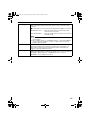
This manual describes detailed usage of
VN-V25U/26U.
For basic usage of VN-V25U/26U, please
refer to AStart-up GuideB.
For latest information, please refer to
AReadmeB file in the CD-ROM.
● The supplied CD-ROM includes
AInstructions (this manual)B(pdf), AAPI
GuideB(pdf), ASearch toolB and AWhite
Spot Correction ToolB.
FOR USA-California Only
This product contains a CR Coin Cell Lithium
Battery which contains Perchlorate Material -
special handling may apply.
See
www.dtsc.ca.gov/hazardouswaste/perchlorate
ENGLISH
DEUTSCH
VN-V25U_26U_EN.book Page 3 Friday, January 18, 2008 2:56 PM

4
Getting Started
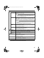
These are general IMPORTANT SAFEGUARDS and certain items may not apply to all appliances.
1. Read all of these instructions.
2. Save these instructions for later use.
3. All warnings on the product and in the operating instructions should be adhered to.
4. Unplug this appliance system from the wall outlet before cleaning. Do not use liquid cleaners or
aerosol cleaners. Use a damp cloth for cleaning.
5.
Do not use attachments not recommended by the appliance manufacturer as they may cause hazards.
6. Do not use this appliance near water - for example, near a bathtub, washbowl, kitchen sink, or
laundry tub, in a wet basement, or near a swimming pool, etc.
7.
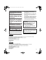
Do not place this appliance on an unstable cart, stand, or table. The appliance may
fall, causing serious injury to a child or adult, and serious damage to the appliance.
Use only with a cart or stand recommended by the manufacturer, or sold with the
appliance. Wall or shelf mounting should follow the manufacturer’s instructions,
and should use a mounting kit approved by the manufacturer. An appliance and
cart combination should be moved with care.
Quick stops, excessive force, and uneven surfaces may cause the appliance and
cart combination to overturn.
8. Slots and openings in the cabinet and the back or bottom are provided for
ventilation, and to insure reliable operation of the appliance and to protect it from
overheating, these openings must not be blocked or covered. The openings
should never be blocked by placing the appliance on a bed, sofa, rug, or other similar surface.
This appliance should never be placed near or over a radiator or heat register. This appliance should
not be placed in a built-in installation such as a bookcase unless proper ventilation is provided.
9.
This appliance should be operated only from the type of power source indicated on the marking label.
If you are not sure of the type of power supplied to your home, consult your dealer or local power
company. For appliance designed to operate from battery power, refer to the operating instructions.
10.For added protection for this product during a lightning storm, or when it is left unattended and
unused for long periods of time, unplug it from the wall outlet and disconnect the antenna or cable
system. This will prevent damage to the product due to lightning and power-line surges.
11.Do not allow anything to rest on the power cord. Do not locate this appliance where the cord will be
abused by persons walking on it.
12.Follow all warnings and instructions marked on the appliance.
13.Do not overload wall outlets and extension cords as this can result in fire or electric shock.
14.Never push objects of any kind into this appliance through cabinet slots as they may touch
dangerous voltage points or short out parts that could result in a fire or electric shock. Never spill
liquid of any kind on the appliance.
15.Do not attempt to service this appliance yourself as opening or removing covers may expose you to
dangerous voltage or other hazards. Refer all servicing to qualified service personnel.
16.Unplug this appliance from the wall outlet and refer servicing to qualified service personnel under
the following conditions:
a. When the power cord or plug is damaged or frayed.
b. If liquid has been spilled into the appliance.
c. If the appliance has been exposed to rain or water.
d. If the appliance does not operate normally by following the operating instructions. Adjust only those controls
that are covered by the operating instructions as improper adjustment of other controls may result in damage
and will often require extensive work by a qualified technician to restore the appliance to normal operation.
e. If the appliance has been dropped or the cabinet has been damaged.
f. When the appliance exhibits a distinct change in performance - this indicates a need for service.
17.When replacement parts are required, be sure the service technician has used replacement parts
specified by the manufacturer that have the same characteristics as the original part. Unauthorized
substitutions may result in fire, electric shock, or other hazards.
18.Upon completion of any service or repairs to this appliance, ask the service technician to perform
routine safety checks to determine that the appliance is in safe operating condition.
IMPORTANT SAFEGUARDS
PORTABLE CART WARNING
(symbol provided by RETAC)
S3125A
VN-V25U_26U_EN.book Page 4 Friday, January 18, 2008 2:56 PM

5
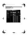
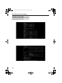
Getting Started ................................... 2
Safety Precautions ..................................... 2
Main Features ............................................. 6
Operating Environment ............................... 7
Cautionary Notes ........................................ 8
Name and Function of Parts ..................... 10
Front / Bottom / Side ............................. 10
Side ....................................................... 11
Rear ...................................................... 12
Features ................................................... 13
Setup Procedures ..................................... 15
Connection / Installation ................. 16
Mounting the Lens .................................... 16
Power Connection .................................... 17
Connecting to the AC 24 V power
supply ............................................ 17
Using the PoE ....................................... 18
LAN Cable Connection ............................. 19
Monitor Signal Output Terminal
Connection ........................................ 19
Connecting the audio signal output
terminal (VN-V26U only) ................... 19
Alarm Input/Output Terminal
Connection ........................................ 20
Alarm Input Terminal ............................ 20
Alarm Output Terminal .......................... 20
Mounting the Camera ............................... 21
Mounting to the Housing Using the Inner
Tripod Base ....................................... 22
Back Focus Adjustment ............................ 23
Network Requirements ............................. 24
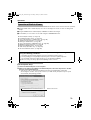
Network Settings ............................. 27
IP Address Settings .................................. 27
Setting the IP address for
VN-V25U/26U ............................... 27
When the IP address of
VN-V25U/26U is known ................ 32
When the IP address of
VN-V25U/26U is unknown ............ 32
Setting Using Internet Explorer ......33
Setup ........................................................ 33
Internet Explorer Setup ......................... 33
Setting ...................................................... 36
View Page ............................................. 36
Camera Page ........................................ 38
Encoding Page ..................................... 44
Audio Page (VN-V26U only) ................. 46
Alarm Page ........................................... 47
Alarm Environment Page ...................... 52
Privacy Mask Page ............................... 56
Motion Detection Page ......................... 58
Basic Page ............................................ 60
Details Page ......................................... 62
Protocol Page ....................................... 63
Streaming Page .................................... 64
Access Restrictions Page ..................... 66
Time Page ............................................ 68
Password Page ..................................... 69
Maintenance Page ................................ 70
LED State Page .................................... 71
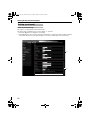
List of Factory Settings of Each Page ... 72
Miscellaneous Page .............................. 74
Operation Page ..................................... 75
Settings Page ....................................... 76
Operation ..........................................79
Operation of Built-in Viewer ...................... 79
Internet Explorer Setup ......................... 79
Installing the built-in viewer ................... 81
Screen Configuration of JPEG
Viewer ........................................... 82
JPEG Viewer Configuration .................. 84
Exiting the JPEG Viewer ....................... 87
Screen Configuration of MPEG4
Viewer ........................................... 88
MPEG4 Viewer Configuration ............... 90
Exiting the MPEG4 Viewer ................... 93
Audio Setup (VN-V26U only) ................ 94
Shortcut for Built-in Viewer ................... 96
Others ................................................97
Troubleshooting ........................................ 97
Specifications ......................................... 100
Dimension ........................................... 102
Contents
VN-V25U_26U_EN.book Page 5 Friday, January 18, 2008 2:56 PM

6
Getting Started
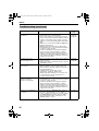
䡵 High Picture Quality
The camera unit of this product employs a
330,000-pixel CCD (1/4") which enables high
quality video surveillance.
䡵 Support for Dual Stream
Simultaneous distribution of JPEG and MPEG4
images is possible.
䡵 Realization of Full Frame Rate
Data transmission is possible in VGA size at a
rate of 30 fps.
䡵 Support for Multicast
This product supports multicast, which enables
transmission of image data to multiple
computers on the network without lowering the
frame rate. (Audio is supported for VN-V26U)
䡵 Built-in Web Server
You can configure the picture quality and
communication settings using the Internet
Explorer.
䡵 HTTP-based API
This product comes with HTTP-based API. This
feature enables you to perform setting and
control via the network.
䡵 Electronic Sense Up
You can shoot images during surveillance at a
dark place by lengthening the exposure time to
enhance the camera’s sensitivity level.
䡵 Night Surveillance
This product comes with a low luminance
feature, which switches automatically to the high
sensitivity mode (black-and-white).
VN-V26U is equipped with an infrared ray cutoff
filter plug that enables day and night
surveillance. Turning off the infrared ray cutoff
filter when the light intensity level is low, such as
at night, enables you to switch to the high
sensitivity mode (B&W mode).
In the case of VN-V25U, you can switch to a
simple high sensitivity mode by turning off the
color signals when the light intensity level is low,
such as at night (Easy day and night mode).
䡵 Privacy Mask
You can configure the privacy mask setting to
hide specific area in shooting area.
䡵 Motion Detection
This feature enables output of an alarm upon
detection of motion in the video image within
preset area.
Pre-/Post-recorded image files may be sent via
FTP using the alarm input.
䡵 Support for PoE (Power over
Ethernet)
This product supports PoE (IEEE802.3af) and
enables power supply from a LAN cable.
PoE: class 2 (VN-V25U)
class 0 (VN-V26U)
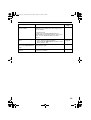
䡵
Built-in JPEG and MPEG4 Viewer
Monitoring of JPEG and MPEG4 images via a
computer is possible by downloading the built-in
viewer onto the computer.
VN-V26U also enables monitoring of audio using
the computer.
䡵 Analog Monitor Signal Output (For
Installation)
This product comes with an analog video
monitor signal output terminal for adjusting the
camera angle during installation.
䡵 Compatibility with Conventional
Peripheral Devices
This product comes in the same shape as
conventional CCTV security cameras, and
therefore can be used with other peripheral
devices for security cameras such as housings.
䡵 Built-in microphone and audio output
terminal (VN-V26U only)
Built-in microphone enables sending audio to
computers. And this product can receive audio
from a computer and output to audio terminal.
Main Features
VN-V25U_26U_EN.book Page 6 Friday, January 18, 2008 2:56 PM

7
䡵 Recommended Computer
Specifications
OS : Windows XP (Professional or
Home Edition) (SP2)
CPU : Pentium4 1.5 GHz or higher
Memory capacity
: 1 GB or more
Free hard disk space
: 512 MB or more
Display and video card
: 1024⳯ 768 pixels or larger,
True Color (24 or 32 bits)
VRAM 8 MB or more (256 MB
and above recommended)
Sound card (VN-V26U only)
: Sound Blaster (PCI
recommended)
Web browser : Internet Explorer
Version 6.0
䡵 LAN Environment
● 10BASE-T/100BASE-TX network
interconnected using devices such as an
IEEE802.3-compliant switching hub.
● IEEE802.3af-compliant switching hub when
PoE is in use.
●
IGMPv2-compliant network when multicast is
in use.
Note:
● The above PC specifications are guides for
smooth use of the applications, and not a
guarantee of their operation.
● Depending on the condition of use,
applications may not run smoothly even
when the user’s computer meets the
specification requirements.
● Using a computer for which its performance
does not meet the requirements may cause
the JPEG playback frame rate to deteriorate.
In addition, it also causes delay in the
MPEG4 playback images, and may result in
interruption in playback.
Audio may be interrupted. (VN-V26U only)
● To make use of the built-in MPEG4 Viewer of
VN-V25U/26U, install “ffdshow” that is open
source codec. You can download “ffdshow”
from the Internet.
● AD/DA clock varies significantly depending
on the sound card built in the PC. Using such
card may cause overflow or underflow of
audio data and noise may occur in the
playback sound.
How to use this manual
䡵 Symbols used
Caution : Describes precautions concerning
the operation of this product.
Note : Describes reference information,
such as functions and usage
restrictions of this product.
A : Indicates the reference page
numbers and reference items.
䡵 Diagrams and images on features
that are common between VN-V25U
and VN-V26U are indicated as
VN-V25U.
䡵 Content of this manual
● All rights reserved by JVC. Unauthorized
duplication or reprinting of this manual, in
whole or in part, is strictly prohibited.
● Windows is a registered trademark of
Microsoft Corporation in the U.S.
● All other product names used in this
manual are trademarks or registered
trademarks of their respective companies.
Marks such as 姠, 姞 and 姝 have been
omitted in this manual.
● Illustrated designs, specifications and other
contents of this manual are subject to
changes for improvement without prior
notice.
Operating Environment
VN-V25U_26U_EN.book Page 7 Friday, January 18, 2008 2:56 PM

8
Getting Started
Maintenance and location of use
䢇 This product is intended for use indoors.
Make sure that you use a housing etc., when
using it outdoors.
䢇 Do not place this product in the following
environments.
Otherwise, it may malfunction or break down.
● Hot or cold locations beyond the
surrounding temperature range of -10°C
to 50°C.
● Locations beyond the allowable operating
humidity range of 20 % to 85 %.
(condensation is not allowed)
●
Near equipment that emits strong magnetic
fields, such as transformers or motors.
● Near equipment that emits radio waves,
such as transceivers and mobile phones.
● Locations with excessive dust or sand.
● Locations that are subject to excessive
vibration.
● Locations prone to moisture such as
window side.
● Locations subject to steam or oil, such as
kitchens.
● Locations that emit radiation, X-rays or
corrosive gases.
䢇 Use of this product or cables connected to
this product at locations where strong electric
waves and magnetic fields are emitted (e.g.,
near radio, TV, transformer, monitor, etc.)
may cause noise interferences in the images
or changes in the color.
䢇 Do not install this product at locations that
may trap heat.
This product also discharges heat from the
surface of the camera unit. As such, do not
install it at locations that may trap heat, such
as near walls.
Handling Precautions
䢇 Do not hang on this product, shake it, or hand
objects over it. Applying an excessive load
may cause the product to fall off and result in
accidents.
䢇 Do not stack up the equipment.
Heat or noise of an equipment may cause
malfunction or failure of the other, and result
in fire.
䢇 Do not block vents around the equipment.
Inadequate heat ventilation may result in
malfunction of this product. Be sure not to
block vents around the product.
Saving Energy
䢇 When this product is not in use for a long
period of time, turn off the power of the
system to ensure safety and reduce power
consumption.
Maintenance
䢇 Be sure to turn off the power before
performing maintenance.
䢇 Wipe this product using a soft cloth.
Wiping with thinner or benzene may melt or
tarnish its surface. For dirt that cannot be
easily removed, wipe using a neutral
detergent diluted with water, followed by
wiping with a dry cloth.
Copyright Protection
䢇 With the exception of the user being the
copyright holder or when permission such as
for duplication has been granted by the
copyright holder, permission is required in
principle for the duplication, modification, or
transmission of copyrighted video and audio
data.
Unauthorized duplication, modification, or
transmission of copyrighted material may
constitute a copyright infringement, and the
user may be liable to compensate for any
damages. When using copyrighted video/
audio data, be sure to check the license
agreement of the copyrighted material
thoroughly.
When rights or rights holders are involved
with regard to the targeted duplicating
subject, permission may be required for
shooting or using (processing) it. Be sure to
check the licensing conditions thoroughly.
Exemption of Liability
䢇 The motion detection feature is not a feature
to prevent theft or fire. JVC shall not be liable
for any damage that occurs.
䢇 JVC shall not be liable for any damage due to
the invasion of privacy by images of this
camera.
Others
䢇 The cable stopper of the alarm terminal may
come off in some cases. When mounting the
cables, make sure to do so carefully.
Cautionary Notes
VN-V25U_26U_EN.book Page 8 Friday, January 18, 2008 2:56 PM

9
䢇 If a high luminance object (such as a lamp) is
shot, a white smear may appear at the upper
and lower ends of this object on the screen.
This phenomenon (smear) is characteristic of
solid-state image sensors, and is not a
malfunction.
䢇 Some hubs/switches of products that are
equipped with intelligent features may
include a broadcast/multicast suppression
function. Viewing of multicast images on this
product may fail if this function is enabled.
䢇 Electricity can be supplied to this product
either by connecting the AC 24 V power
supply or using the PoE. Make sure to select
only one mode of electrical supply.
Connecting the power cord and the LAN
cable for the PoE at the same time may result
in failure or malfunction of the camera.
(A Page 17, 18)
䢇 This product comes with a built-in AGC
circuit. When using this product with AGC set
to AMidB, AHighB or ASuperB, the sensitivity
level increases when the image is dark, and
the screen may appear grainy as a result.
However, this is not a malfunction.
䢇 When using this product with the white
balance set to AATWB, the displayed color
may differ slightly from the actual color
according to the condition of the object due to
the principle of the automatic tracking white
balance circuit. This is not a malfunction.
䢇
The electronic shutter of this product is set to
A
1/30
B
by default. For regions with a
commercial power supply frequency of 50 Hz,
switch to the flickerless mode during use
under fluorescent lights (excluding inverter
lighting equipment) to prevent flickers.
䢇 When the Black-and-white mode (VN-V26U)
or Easy Day and Night mode (VN-V25U) is
enabled, the image becomes black-and-white
in a dark place. As the sensitivity level is
increased in this case, the screen may
appear grainy and more white spots may
appear. When switching between color and
black-and-white images, the brighter area on
the screen is emphasized, which may reduce
the visibility. However, this is not a
malfunction.
䢇
If the power supply voltage is momentarily cut
off or reduced due to lightning, turning on of
the air conditioner’s power, etc., the image
may be disrupted or noise interference may
occur.
䢇
When using multicast, make use of a
IGMPv2-compliant network switch.
䢇
In the case of VN-V26U, the image and sound
may not synchronize when playing back using
built-in viewer. This is not a malfunction.
䢇
When VN-V26U is sending high bitrate, the
image and sound can be paused during
Black-and-white mode changing. This is not a
malfunction.
VN-V25U_26U_EN.book Page 9 Friday, January 18, 2008 2:56 PM

10
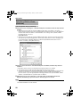
Getting Started
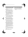
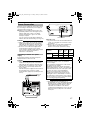
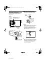
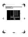
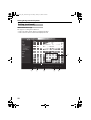
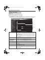
Front / Bottom / Side
A
Back Focus Adjustment Ring
This ring is used for back focus adjustment and
switching the lens mount method.
To operate, loosen the I back focus fastening
screw by turning it in the anti-clockwise direction,
and turn the screw in the clockwise direction to
fasten after operation is complete.
This product is pre-adjusted to a position that is
best suited for CS mount.
(A Page 23)
B Lens Mount
This is a mount for mounting the lens.
The mount is compatible with CS mount lens
and C mount lens.
(A Page 16)
C Camera Mounting Bracket Fastening
Screw (2 pcs: M2.6 x 6 mm)
Use screws with a length of 6 mm. Screws
beyond the specified length must not be used as
doing so may damage the interior.
D Anti-rotation Hole
Use this anti-rotation hole to mount the camera
firmly.
E Camera Mounting Screw Holes
(1/4-20UNC)
Use this hole when mounting this product to a
fixer or rotating platform.
Use screws with a length between 5 mm to
7 mm. Screws beyond the specified length may
damage the interior, while those shorter than
specified may cause the camera to fall off, and
therefore these must not be used.
(A Page 21)
F Built-in Microphone (VN-V26U only)
Audio picked up using this microphone is sent to
computers.
G [MAC address] Indicator
The MAC address is a unique physical address
of the product. This address cannot be altered.
H Camera Mounting Bracket
This bracket is pre-mounted to the bottom
surface of the camera. It can also be mounted to
the top surface according to the usage. Mount it
to the screw holes at the top surface using the C
camera mounting bracket fastening screws.
(A Page 21)
I [BF LOCK] Back Focus Fastening Screw
This is the fastening screw for the back focus
adjustment unit. (A Page 23)
J Inner Tripod Base Screw Hole (1/4-20UNC)
Use this hole when mounting this product to a
miniature housing.
You can mount to the housing through this hole
directly without using the H camera mounting
bracket. (A Page 22)
Name and Function of Parts
A
B
C
D
E
H
F
G
J
I
The model illustrated in the diagram is VN-V26U.
VN-V25U_26U_EN.book Page 10 Friday, January 18, 2008 2:56 PM

11
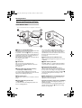
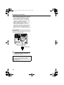
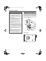
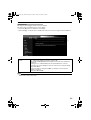
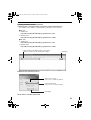
Side
K
[MONITOR OUT] Monitor Output Selection
Switch
Use this switch to select the availability of output
from the O [MONITOR OUT] terminal as well as
the signal system.
NTSC : Outputs NTSC signals.
OFF : No output. Select this value when
distributing images to the network.
PAL : Outputs PAL signals.
[Default setting: OFF]
Caution:
● Images are not distributed to the network
when ANTSCB or APALB is selected.
● When the switch is changed, press the L
Reset button to reboot the unit.
L [RESET] Reset Button
This is a button for rebooting the camera. Press
this button and release within 5 seconds to
reboot the camera.
It takes about one minute for the camera to
reboot. During startup, the [RESET] button is
disabled.
Note:
Pressing the [RESET] button for 5 seconds or
longer switches the camera to the service
verification mode. Do not press the button for 5
seconds or longer.
M [IRIS] Iris Terminal
Use this terminal to connect the DC iris lens.
(Connection with the video iris lens is not
possible.)
(A Page 16)
N [STATUS] Status Indicator
This status of this product is indicated in green
or orange color.
Starting up: Lights up in orange
Startup complete: Lights up in green
Error: Blinks in orange
Note:
You can adjust the [LED State] settings via the
network to turn off the indicator after startup is
complete. (A Page 71)
STATUS
MONITOR OUT
IRIS
PAL OFF NTSC
RESET
L
K
MN
VN-V25U_26U_EN.book Page 11 Friday, January 18, 2008 2:56 PM

12
Getting Started
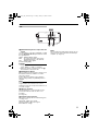
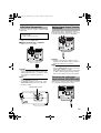
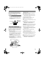
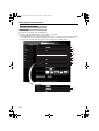
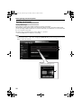
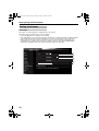
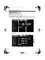
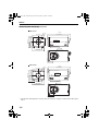
Rear
O
[MONITOR OUT] Monitor Video Signal
Output Terminal (RCA)
This is an output terminal for composite video
signals (1 V (p-p), output impedance of 75 K).
Use this terminal to connect to devices such as a
video monitor.
This terminal is used for adjusting the camera
angle during installation. (A Page 19)
Note:
● Use the K [MONITOR OUT] switch to select
the availability of output as well as the signal
system. When the switch is changed, press
the L Reset button to reboot the unit.
● When using the [MONITOR OUT] output, set
the privacy mask to AOffB. (A Page 56)
P [10BASE-T/100BASE-TX]
Use this terminal to connect to the network via a
LAN cable.
This product supports PoE (IEEE802.3af) and
therefore can be used without a power cable.
PoE: class 2 (VN-V25U)
class 0 (VN-V26U)
(A Page 17)(A Page 19)
Q [ALARM INPUT/OUTPUT] Alarm Input/
Output Terminals
Use these terminals to connect to an external
alarm device.
(A Page 20)
R [AC24V] Power Input Terminal
Use this terminal to connect to an AC 24 V,
50/60 Hz power supply.
(A Page 17)
S Fall Prevention Wire Mounting Screw
(M3 x 6 mm)
Use this screw to mount the fall prevention wire.
(
A
Page 21)
T [AUDIO OUT] Audio signal output terminal
(mini jack R3.5 mono) (VN-V26U only)
Outputs audio (analog) received from a
computer.
Does not output audio from the F built-in-
microphone.
CAUTION
: NEVER USE
PoE
AND
AC 24V
AT THE SAME TIME
DO NOT CONNECT TO THE TELEPHONE NETWORK
SEE INSTRUCTION MANUAL
CLASS 2 ONLY FOR USA
ISOLATED POWER ONLY
FOR EUROPE AND OTHER
MONITOR
OUT
AUDIO OUT
10BASE-T/
100BASE-TX
PUSH
OUTPUT
ALARM
INPUT
2
AC24V
1
PoE
G 2 1 2 1
CAUTION
: NEVER USE
PoE
AND
AC 24V
AT THE SAME TIME
DO NOT CONNECT TO THE TELEPHONE NETWORK
SEE INSTRUCTION MANUAL
CLASS 2 ONLY FOR USA
ISOLATED POWER ONLY
FOR EUROPE AND OTHER
MONITOR
OUT
10BASE-T/
100BASE-TX
PUSH
OUTPUT
ALARM
INPUT
2
AC24V
1
PoE
G 2 1 2 1
VN-V25U
VN-V26U
R
Q
R
Q
SS
O
P
T
PO
VN-V25U_26U_EN.book Page 12 Friday, January 18, 2008 2:56 PM

13
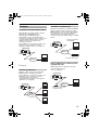
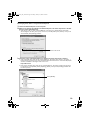
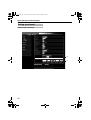
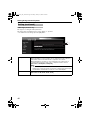
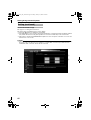
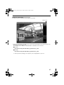
Surveillance Using the Built-in Viewer
VN-V25U/26U comes with a built-in ActiveX
JPEG Viewer and MPEG4 Viewer.
JPEG images and MPEG4 images of
VN-V25U/26U can be monitored using the
computer by installing this built-in viewer on the
computer. JPEG images that are currently
displayed can also be captured in the
computer’s hard disk.
For VN-V26U, you can check the audio of the
built-in microphone using the computer.
AOperation of Built-in ViewerB (A Page 79)
VN-V25U/26U accepts requests from 20 clients
at maximum.
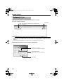
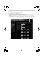
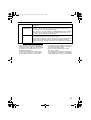
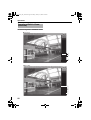
Monitoring via Multicast
Multicast enables monitoring of JPEG and
MPEG4 images on multiple computers.
For VN-V26U, you can check the audio of the
built-in microphone using the computer.
AStreaming PageB (A Page 64)
AJPEG Viewer ConfigurationB (A Page 84)
AOperationB (A Page 90)
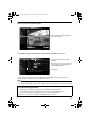
Surveillance via Dual Stream
Simultaneous distribution of JPEG and MPEG4
images enables real-time surveillance using
MPEG4 (30 fps) and recording of JPEG images
at the same time. You can also lengthen the
recording time by lowering the frame rate,
resolution, and picture quality settings for JPEG
images.
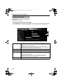
Saving JPEG images to the FTP server
at regular intervals
JPEG images may be uploaded to the FTP
server at regular intervals.
AFTPB (A Page 53)
Features
MAC address
Computer
VN-V25U/26U
Network
MAC address
Computer
Compute
r
Computer
IGMP-
Compliant
Network
VN-V25U/26U
MAC address
Computer
Real-time Surveillance
Using MPEG4
Network
VN-V25U/26U
Storage Device
Recording JPEG Images
MAC address
Computer
Uploads the latest JPEG
images to the FTP server
at regular intervals
Network
VN-V25U/26U
VN-V25U_26U_EN.book Page 13 Friday, January 18, 2008 2:56 PM

14
Getting Started
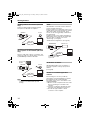
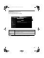
Sending audio to the network (VN-V26U
only)
Sends out audio picked up using the built-in
microphone of VN-V26U to computers.
Receiving and outputting audio from
the computer via the network (VN-V26U
only)
Receives audio that is input to a computer, and
outputs the audio to a speaker that is connected
to [AUDIO OUT] terminal of VN-V26U.
Note:
● Use of a headset for audio input/output of the
computer is recommended to prevent
howling.
Alarm
VN-V25U/26U comes with a motion detection
feature and dual alarm input.
By motion detection or alarm input, actions such
as mail delivery, message transmission via TCP/
UDP, alarm output can be triggered. These
actions can also be triggered by combination of
two alarm inputs.
Installing an FTP server enables uploading of
JPEG images before and after the alarm input
time (pre-/post-recording) to the server.
AAlarm PageB (A Page 47)
AJPEG Viewer ConfigurationB (A Page 84)
Restrictions on Clients
VN-V25U/26U enables users to authorize or
reject the acquisition of images by specific IP
address.
(
A
Page 66)
Control via customized application
software
The following uses are also possible by
developing a customized application software
that supports the API of VN-V25U/26U.
For details, please refer to AAPI GuideB in the
supplied CD-ROM.
● Monitors via the computer while at the same
time records images to the HDD of the
computer.
● Performs recording by changing the frame
size/frame rate during alarm occurrence.
● Records the type and time of alarm
occurrence on the computer.
MAC address
Network
Computer
Headset
VN-V26U
Built-in
mike
MAC address
Network
Speaker with
amplifier
VN-V26U
Headset
Computer
MAC address
Computer
Sending JPEG images
before and after alarm
input to FTP
Alarm Device
Network
VN-V25U/26U
VN-V25U_26U_EN.book Page 14 Friday, January 18, 2008 2:56 PM

15
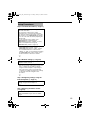
Step 1 Connection/Installation (
A
Page 17)
T After adjusting the camera angle using the
[MONITOR OUT] terminal, set the
[MONITOR OUT] switch to AOFFB. Images
are not distributed to the network when
ANTSCB or APALB is selected. After changing
the [MONITOR OUT] switch setting, press
the Reset button to reboot the camera.
G
Step 2 Network settings (A Page 27)
T In a system where multiple units of VN-V25U/
26U are used, turn on the power of only one
unit to configure the IP address settings
using the Internet Explorer. Upon doing so,
turn on the power of the second unit and
configure accordingly. Configure the settings
for the other cameras using the same
procedure.
G
Step 3 Configuring settings using the
Internet Explorer (A Page 33)
G
Step 4 Operating the built-in viewer
(A Page 79)
Setup Procedures
Connect the lens mount, power supply cord,
LAN cable and alarm.
Next, mount the camera to the ceiling.
Remember also to mount the fall prevention
wire. After the camera is mounted, connect the
video monitor to the [MONITOR OUT] terminal
at the rear of the unit, followed by adjusting the
camera angle.
You can select the video signals of the
[MONITOR OUT] terminal using the
[MONITOR OUT] switch. (
A
NTSC
B
or
A
PAL
B
)
(Back focus adjustment
A
Page 23)
([MONITOR OUT] switch
A
Page 11)
Configure the network settings of the
computer and this camera.
Configure the picture quality and alarm
settings using the Internet Explorer.
The built-in viewers enable you to monitor
JPEG and MPEG4 images and save JPEG
images.
VN-V25U_26U_EN.book Page 15 Friday, January 18, 2008 2:56 PM

16
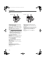
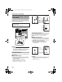
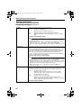
Connection / Installation
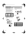
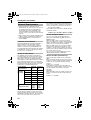
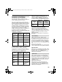
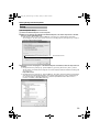
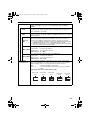
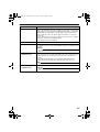
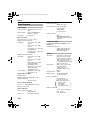
1.Check the mounting method of the lens to
be used before mounting
● The default method used for this camera is
CS mount. To use a C mount lens, loosen the
back focus fastening screw using a
screwdriver, followed by turning the back
focus adjustment ring using a finger or
pointed object (e.g., screwdriver, etc.) to
change the mount method.
● Make use of the values listed in the table
below for the dimensions of the lens mount
(a) indicated in the following diagram.
● Objects longer than the dimension (a) must
not be used as doing so may damage the
camera interior or prevent the lens from
being properly mounted, hence resulting in
malfunctions.
2.Turn the lens in the clockwise direction to
mount it to the camera firmly
3.When using a DC iris lens, pay attention
to the pin position before connecting the
lens cable
4.Pin Plug
Mounting the Lens
Lens
Flange Focus (b)
Dimension (a)
C Mount
Lens
17.526 mm VN-V25U: 10
mm and below
VN-V26U: 5.5
mm and below
CS Mount
Lens
12.5 mm 5.5 mm and
below
(a)
(b)
F
Loosen
Back Focus Fastening
Screw (M2.6)
Pin No.
DC Iris Lens
(Without Built-in EE Amplifier)
1 Damping (-)
2 Damping (+)
3 Driving (+)
4 Driving (-)
STATUS
MONITOR OUT
IRIS
PAL OFF NTSC
RESET
3
42
1
3.
2.
1
3
2
4
VN-V25U_26U_EN.book Page 16 Friday, January 18, 2008 2:56 PM

17
Electricity can be supplied to this product either
by connecting to the AC 24 V power supply or
using the PoE (A Page 18).
䢇
When power is supplied to this product, the
[STATUS] indicator at the side lights up. The
indicator lights up in orange color during
startup, and switches to green color after
startup is complete.
You can select not to light up the [STATUS]
indicator when the unit is running. (
A
Page 71)
Caution:
●
Make sure to select only one mode of electrical
supply. Connecting the power cord and the
LAN cable for the PoE at the same time may
result in failure or malfunction of the camera.
● Be sure to use an AC 24 V supply that is
isolated from the primary power supply
circuit. Using a variable voltage power supply
will cause the camera and system to
malfunction or breakdown.
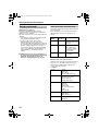
Connecting to the AC 24 V power
supply
Connect this product to the AC 24 V power
supply when the PoE is not used.
Caution:
●
Make sure to select only one mode of electrical
supply. Connecting the power cord and the
LAN cable for the PoE at the same time may
result in failure or malfunction of the camera.
● The unit is to be powered by an AC 24 V
power supply.
The AC 24 V power supply should conform to
the following: Class 2 only (For USA),
Isolated power supply only (For Europe and
others).
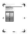
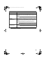
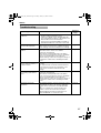
䢇 Power cord
● To prevent misconnection and detachment of
cords, use a lug plate to connect the cord to
the terminal.
● When a two-core VVF (vinyl insulated vinyl
sheath cable) is used, the connection
distance is as follows. (Reference value)
Note:
●
After DHCP timeout, all IP addresses of
VN-V25U/26Us are set to 192.168.0.2 by default.
When the power of multiple cameras within the
same LAN environment are turned on at the
same time, the IP address of the cameras
overlap, thus preventing proper access. As such,
make sure to turn on the power of the cameras
one by one.
Power Connection
CAUTION
: NEVER USE
PoE
AND
AC 24V
AT T H E S A M E T I M E
DO NOT CONNECT TO THE TELEPHONE NETWORK
SEE INSTRUCTION MANUAL
CLASS 2 ONLY FOR USA
ISOLATED POWER ONLY
FOR EUROPE AND OTHER
MONITOR
OUT
10BASE-T/
100BASE-TX
PUSH
OUTPUT
INPUT
2
AC24V
1
PoE
G 2121
ALARM
To Power
Supply
Conductor Diameter
(AWG No.)
R
1.0 mm
(18) and
above
R
1.6 mm
(14) and
above
R
2.0 mm
(12) and
above
Maximum
Extension
VN-V25U 150 m 400 m 630 m
VN-V26U 90 m 240 m 370 m
Warning
The rated power of this product is AC 24 V,
50 Hz/60 Hz. Make sure to use it with the
correct voltage.
Use an AC 24 V supply that is isolated from
the primary power supply.
Supplying a power beyond the rated value
may result in failures, smoke or fire. When the
camera breaks down, turn off the power and
contact our service center immediately.
When a power beyond the rated value is
supplied, the internal components may be
damaged even if no abnormality is found on
the appearance and operation of the camera.
Please contact our service center immediately
for servicing (charged separately).
STATUS
MONITOR OUT
IRIS
PA L OF F N T S C
RESET
Status Indicator
VN-V25U_26U_EN.book Page 17 Friday, January 18, 2008 2:56 PM

18
Connection / Installation
● In a system where multiple units of VN-V25U/
26U are used, turn on the power of only one
unit to configure the IP address settings
using the Internet Explorer. Upon doing so,
turn on the power of the second unit and
configure accordingly. Configure the camera
settings using the same procedure.
● When overlapping of the IP address occurs,
check to ensure that there is only one
VN-V25U/26U unit within the same LAN
environment, and wait for a while (at least 10
minutes) or power off and on all network
devices under the same LAN environment.
Otherwise, access to VN-V25U/26U may fail.
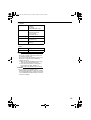
Using the PoE
Connect to a device that supports PoE to supply
electricity from the LAN cable.
Note:
● For details on the connection method and
cable type, please refer to ALAN Cable
ConnectionB (A Page 19).
What is PoE (Power over Ethernet)?
This is a function that enables operation of a
LAN equipment without a power cable by
supplying power simultaneously with the data
using a LAN cable.
CAUTION
: NEVER USE
PoE
AND
AC 24V
AT THE SAME TIME
DO NOT CONNECT TO THE TELEPHONE NETWORK
SEE INSTRUCTION MANUAL
CLASS 2 ONLY FOR USA
ISOLATED POWER ONLY
FOR EUROPE AND OTHER
MONITOR
OUT
10BASE-T/
100BASE-TX
PUSH
OUTPUT
INPUT
2
AC24V
1
PoE
G 2121
ALARM
Connect to PoE-
compatible device
VN-V25U_26U_EN.book Page 18 Friday, January 18, 2008 2:56 PM

19
Connect the camera to a hub or computer using
a LAN cable.
䡵 When connecting to a hub
Make use of a straight cable.
䡵 When connecting to a computer
Make use of a cross cable.
Caution:
● However, cross cables cannot be used with
some computer models. When connecting
VN-V25U/26U directly to a computer, check
the computer’s LAN specifications in
advance.
Note:
● Make use of a Category 5 (or higher) cable
when 100BASE-TX is used.
● To distribute images to the network, set the
[MONITOR OUT] switch at the side of this
product to AOFFB.
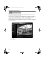
This terminal is used for adjusting the camera
angle during installation. Connect it to devices such
as a video monitor using a video cable (RCA).
Caution:
● A longer cable extension distance causes
signals to be attenuated, image resolution to
deteriorate and noise to increase.
Note:
●
Select the signal system for the monitor output
using the [MONITOR OUT] switch at the side of
this product. (
A
NTSC
B
or
A
PAL
B
)
After adjusting the camera angle, set the switch
to
A
OFF
B
. After changing the switch settings,
press the Reset button to reboot the camera.
Connect to the speakers with a built-in amplifier,
etc. using mini jack (R3.5 mono) cable.
LAN Cable Connection
Cable to use
● Shielded cable
● Length of 100 m or shorter
CAUTION
: NEVER USE
PoE
AND
AC 24V
AT THE SAME TIME
DO NOT CONNECT TO THE TELEPHONE NETWORK
SEE INSTRUCTION MANUAL
CLASS2ONLYFORUSA
ISOLATED POWER ONLY
FOR EUROPE AND OTHER
MONITOR
OUT
10BASE-T/
100BASE-TX
PUSH
OUTPUT
INPUT
2
AC24V
1
PoE
G 2121
ALARM
CAUTION
: NEVER USE
PoE
AND
AC 24V
AT THE SAME TIME
DO NOT CONNECT TO THE TELEPHONE NETWORK
SEE INSTRUCTION MANUAL
CLASS2ONLYFORUSA
ISOLATED POWER ONLY
FOR EUROPE AND OTHER
MONITOR
OUT
10BASE-T/
100BASE-TX
PUSH
OUTPUT
INPUT
2
AC24V
1
PoE
G 2121
ALARM
STATUS
MONITOR OUT
IRIS
PA L OF F N T S C
RESET
[MONITOR OUT] Switch
Monitor Signal Output Terminal
Connection
Connecting the audio signal
output terminal (
VN-V26U only
)
CAUTION
: NEVER USE
PoE
AND
AC 24V
AT THE SAME TIME
DO NOT CONNECT TO THE TELEPHONE NETWORK
SEE INSTRUCTION MANUAL
CLASS2ONLYFORUSA
ISOLATED POWER ONLY
FOR EUROPE AND OTHER
MONITOR
OUT
10BASE-T/
100BASE-TX
PUSH
OUTPUT
INPUT
2
AC24V
1
PoE
G 2121
ALARM
CAUTION
: NEVER USE
PoE
AND
AC 24V
AT T H E S A M E T I ME
DO NOT CONNECT TO THE TELEPHONE NETWORK
SEE INSTRUCTION MANUAL
CLASS 2 ONLY FOR USA
ISOLATED PO
WER ONL
Y
FOR EUR
OPE AND O
THER
MONITOR
OUT
AUDIO OUT
10BASE-T/
100BASE-TX
PUSH
OUTPUT
ALARM
INPUT
2
AC24V
1
PoE
G
2121
VN-V25U_26U_EN.book Page 19 Friday, January 18, 2008 2:56 PM

20
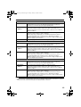
Connection / Installation
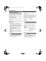
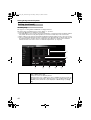
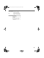
Connect the alarm input/output terminals with
external devices, such as a sensor or buzzer.
Plug/Unplug the cable while pressing the button
as shown in the diagram below.
Caution:
● Noises from an external source may cause
the camera to malfunction even when the
cable used is within 50 m. In this case, move
the cable away from the noise source.
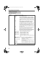
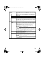
Alarm Input Terminal
Connect this terminal to sensor devices, such as
an infrared sensor, door sensor, metal sensor or
manual switch.
䡵 Input requirements
● No-voltage relay NPN open collector input
● Polarity of input detection can be selected
using a software
● Make/Break (500 ms and above)
● Circuit current at low level: 1 mA
● Applied voltage at high level: 3.3 V
Alarm Output Terminal
Connect this terminal to annunciating devices,
such as annunciators, indicators, lights, or
buzzers.
䡵 Output requirements
● Equivalent to NPN open collector output (Set
the output logic using the Internet Explorer)
● Allowable applied voltage: DC12 V and below
● Allowable inflow current: 50 mA
●
Momentary (100 ms - 5000 ms) output
(Set time using the Internet Explorer
(A Page 52))
Caution:
● Connect the G terminal of this camera to the
GND terminal of the annunciating device or
alarm input sensor.
Alarm Input/Output Terminal
Connection
Cable to use
● Shielded cable
● Length of 50 m or shorter
CAUTION
: NEVER USE
PoE
AND
AC 24V
AT THE SAME TIME
DO NOT CONNECT TO THE TELEPHONE NETWORK
SEE INSTRUCTION MANUAL
CLASS 2 ONLY FOR USA
ISOLATED POWER ONLY
FOR EUROPE AND OTHER
MONITOR
OUT
10BASE-T/
100BASE-TX
PUSH
OUTPUT
ALARM
INPUT
2
AC24V
1
PoE
G 2121
Push
DC3.3 V
R
3.3 V
1 mA
VCC
OUT
GND
GND
OUT
R
(Alarm Input Equivalent Circuit)
G Terminal
INPUT 1 or
2 Terminal
Sensor Example
(1)
Sensor Example
(2)
Relay Switch, etc.
VN-V25U/26U
IN
R
DC 12 V
GND
Annunciating
Device Example
VN-V25U/26U
G Terminal
OUTPUT 1
or 2 Terminal
(Alarm Output Equivalent Circuit)
VN-V25U_26U_EN.book Page 20 Friday, January 18, 2008 2:56 PM
Page is loading ...
Page is loading ...
Page is loading ...
Page is loading ...
Page is loading ...
Page is loading ...
Page is loading ...
Page is loading ...
Page is loading ...
Page is loading ...
Page is loading ...
Page is loading ...
Page is loading ...
Page is loading ...
Page is loading ...
Page is loading ...
Page is loading ...
Page is loading ...
Page is loading ...
Page is loading ...
Page is loading ...
Page is loading ...
Page is loading ...
Page is loading ...
Page is loading ...
Page is loading ...
Page is loading ...
Page is loading ...
Page is loading ...
Page is loading ...
Page is loading ...
Page is loading ...
Page is loading ...
Page is loading ...
Page is loading ...
Page is loading ...
Page is loading ...
Page is loading ...
Page is loading ...
Page is loading ...
Page is loading ...
Page is loading ...
Page is loading ...
Page is loading ...
Page is loading ...
Page is loading ...
Page is loading ...
Page is loading ...
Page is loading ...
Page is loading ...
Page is loading ...
Page is loading ...
Page is loading ...
Page is loading ...
Page is loading ...
Page is loading ...
Page is loading ...
Page is loading ...
Page is loading ...
Page is loading ...
Page is loading ...
Page is loading ...
Page is loading ...
Page is loading ...
Page is loading ...
Page is loading ...
Page is loading ...
Page is loading ...
Page is loading ...
Page is loading ...
Page is loading ...
Page is loading ...
Page is loading ...
Page is loading ...
Page is loading ...
Page is loading ...
Page is loading ...
Page is loading ...
Page is loading ...
Page is loading ...
Page is loading ...
Page is loading ...
Page is loading ...
Page is loading ...
-
 1
1
-
 2
2
-
 3
3
-
 4
4
-
 5
5
-
 6
6
-
 7
7
-
 8
8
-
 9
9
-
 10
10
-
 11
11
-
 12
12
-
 13
13
-
 14
14
-
 15
15
-
 16
16
-
 17
17
-
 18
18
-
 19
19
-
 20
20
-
 21
21
-
 22
22
-
 23
23
-
 24
24
-
 25
25
-
 26
26
-
 27
27
-
 28
28
-
 29
29
-
 30
30
-
 31
31
-
 32
32
-
 33
33
-
 34
34
-
 35
35
-
 36
36
-
 37
37
-
 38
38
-
 39
39
-
 40
40
-
 41
41
-
 42
42
-
 43
43
-
 44
44
-
 45
45
-
 46
46
-
 47
47
-
 48
48
-
 49
49
-
 50
50
-
 51
51
-
 52
52
-
 53
53
-
 54
54
-
 55
55
-
 56
56
-
 57
57
-
 58
58
-
 59
59
-
 60
60
-
 61
61
-
 62
62
-
 63
63
-
 64
64
-
 65
65
-
 66
66
-
 67
67
-
 68
68
-
 69
69
-
 70
70
-
 71
71
-
 72
72
-
 73
73
-
 74
74
-
 75
75
-
 76
76
-
 77
77
-
 78
78
-
 79
79
-
 80
80
-
 81
81
-
 82
82
-
 83
83
-
 84
84
-
 85
85
-
 86
86
-
 87
87
-
 88
88
-
 89
89
-
 90
90
-
 91
91
-
 92
92
-
 93
93
-
 94
94
-
 95
95
-
 96
96
-
 97
97
-
 98
98
-
 99
99
-
 100
100
-
 101
101
-
 102
102
-
 103
103
-
 104
104


JVC IP CAMERA VN-V25U User manual
- Category
- Security cameras
- Type
- User manual
- This manual is also suitable for
Ask a question and I''ll find the answer in the document
Finding information in a document is now easier with AI
Related papers
Other documents
-
Sanyo VCC-HD4000 - Network Camera Quick Reference Manual
-
-
ASSMANN Electronic DN-19 FAN-4-26U Datasheet
-
-
-
 Auralog Tell Tell me More User manual
-
Sanyo VCC-HD2300P User manual
-
 Dymedso Frequencer V2x User manual
-
Toshiba 625012200G User manual
-
 optitrack PRIME SERIES Quick start guide


