Emerson 2051 Wireless Pressure User manual
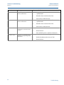
- Category
- Measuring, testing & control
- Type
- User manual
This manual is also suitable for

Reference Manual
00809-0100-4102, Rev AA
May 2013
Rosemount 2051 Wireless Pressure Transmitters
Pressure, Level, and Flow Solutions with WirelessHART™
Protocol


i
Reference Manual
00809-0100-4102, Rev AA
Rosemount 2051 Wireless Pressure, Flow,
and Level Solutions
Read this manual before working with the product. For personal and system safety, and for
optimum product performance, make sure you thoroughly understand the contents before
installing, using, or maintaining this product.
For technical assistance, contacts are listed below:
Customer Central
Technical support, quoting, and order-related questions.
United States - 1-800-999-9307 (7:00 am to 7:00 pm CST)
Asia Pacific- 65 777 8211
Europe/ Middle East/ Africa - 49 (8153) 9390
North American Response Center
Equipment service needs.
1-800-654-7768 (24 hours—includes Canada)
Outside of these areas, contact your local Emerson Process Management representative.
The products described in this document are NOT designed for nuclear-qualified
applications. Using non-nuclear qualified products in applications that require
nuclear-qualified hardware or products may cause inaccurate readings.
For information on Emerson Process Management nuclear-qualified products, contact your
local Rosemount Sales Representative.

ii
Reference Manual
00809-0100-4102, Rev AA
Explosions could result in death or serious injury:
Installation of this transmitter in an explosive environment must be in accordance with the
appropriate local, national, and international standards, codes, and practices. Please review
the approvals section of the 2051 reference manual for any restrictions associated with a
safe installation.
Before connecting a HART-based communicator in an explosive atmosphere, make
sure the instruments in the loop are installed in accordance with intrinsically safe or
non-incendive field wiring practices.
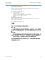
This device complies with Part 15 of the FCC Rules. Operation is subject to the following
conditions.
This device may not cause harmful interference. This device must accept any interference
received, including interference that may cause undesired operation.
This device must be installed to ensure a minimum antenna separation distance of 8 in.
(20cm) from all persons.
Process leaks may cause harm or result in death.
To avoid process leaks, only use the o-ring designed to seal with the corresponding
flange adapter.
Electrical shock can result in death or serious injury.
Avoid contact with the leads and the terminals. High voltage that may be present on
leads can cause electrical shock.
The Rosemount 2051 and all other wireless devices should be installed only after the Smart
Wireless Gateway has been installed and is functioning properly. Wireless devices should
also be powered up in order of proximity from the Smart Wireless Gateway, beginning with
the closest. This will result in a simpler and faster network installation.

iii
Reference Manual
00809-0100-4102, Rev AA
Shipping considerations for wireless products (Lithium Batteries: Green Power Module,
model number 701PGNKF):
The unit was shipped to you without the Power Module installed. Please remove the
Power Module from the unit prior to shipping.
Each power module contains one “D” size primary lithium-thionyl chloride battery.
Primary lithium batteries are regulated in transportation by the U.S. Department of
Transportation, and are also covered by IATA (International Air Transport Association),
ICAO (International Civil Aviation Organization), and ARD (European Ground
Transportation of Dangerous Goods). It is the responsibility of the shipper to ensure
compliance with these or any other local requirements. Please consult current
regulations and requirements before shipping.
The power module with the wireless unit contains one “D” size primary lithium-thionyl
chloride battery (Green Power Module, model number 701PGNKF). Each battery contains
approximately 5.0 grams of lithium. Under normal conditions, the battery materials are
self-contained and are not reactive as long as the battery and the pack integrity are
maintained. Care should be taken to prevent thermal, electrical or mechanical damage.
Contacts should be protected to prevent premature discharge.
Battery hazards remain when cells are discharged.
Power modules should be stored in a clean and dry area. For maximum battery life, storage
temperature should not exceed 30 °C (86 °F).
The Power Module may be replaced in a hazardous area. The Power Module has surface
resistivity greater than one gigaohm and must be properly installed in the wireless device
enclosure. Care must be taken during transportation to and from the point of installation to
prevent electrostatic charge build-up.
Using the Rosemount 2051 Wireless Pressure Transmitter in a manner other than what is
specified by the manufacturer may impair the protection provided by the equipment.

iv
Reference Manual
00809-0100-4102, Rev AA

i
Reference Manual
00809-0100-4102, Rev AA
Table of Contents
May 2013
Table of Contents
1Section 1: Introduction
1.1 Using this manual. . . . . . . . . . . . . . . . . . . . . . . . . . . . . . . . . . . . . . . . . . . . . . . . . . . . . . .1
1.2 Models covered . . . . . . . . . . . . . . . . . . . . . . . . . . . . . . . . . . . . . . . . . . . . . . . . . . . . . . . .1
1.2.1 Rosemount 2051C Coplanar
™
Pressure Transmitter . . . . . . . . . . . . . . . . . . .1
1.2.2 Rosemount 2051T in-line Pressure Transmitter . . . . . . . . . . . . . . . . . . . . . . .1
1.2.3 Rosemount 2051L Level Transmitter . . . . . . . . . . . . . . . . . . . . . . . . . . . . . . . .2
1.2.4 Rosemount 2051CF Flowmeters . . . . . . . . . . . . . . . . . . . . . . . . . . . . . . . . . . . .2
1.3 WirelessHART installation flowchart . . . . . . . . . . . . . . . . . . . . . . . . . . . . . . . . . . . . . .3
1.4 Transmitter overview . . . . . . . . . . . . . . . . . . . . . . . . . . . . . . . . . . . . . . . . . . . . . . . . . . .4
1.5 Considerations before transmitter installation. . . . . . . . . . . . . . . . . . . . . . . . . . . . . .5
1.5.1 Wireless considerations. . . . . . . . . . . . . . . . . . . . . . . . . . . . . . . . . . . . . . . . . . . .5
1.5.2 Mechanical. . . . . . . . . . . . . . . . . . . . . . . . . . . . . . . . . . . . . . . . . . . . . . . . . . . . . . .6
1.5.3 Electrical . . . . . . . . . . . . . . . . . . . . . . . . . . . . . . . . . . . . . . . . . . . . . . . . . . . . . . . . .6
1.5.4 Environmental. . . . . . . . . . . . . . . . . . . . . . . . . . . . . . . . . . . . . . . . . . . . . . . . . . . .7
1.6 Service support. . . . . . . . . . . . . . . . . . . . . . . . . . . . . . . . . . . . . . . . . . . . . . . . . . . . . . . . .7
1.7 Product Recycling/Disposal . . . . . . . . . . . . . . . . . . . . . . . . . . . . . . . . . . . . . . . . . . . . . .8
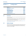
2Section 2: Configuration
2.1 Overview . . . . . . . . . . . . . . . . . . . . . . . . . . . . . . . . . . . . . . . . . . . . . . . . . . . . . . . . . . . . . .9
2.2 Safety messages. . . . . . . . . . . . . . . . . . . . . . . . . . . . . . . . . . . . . . . . . . . . . . . . . . . . . . . .9
2.3 Required bench top configuration . . . . . . . . . . . . . . . . . . . . . . . . . . . . . . . . . . . . . . .10
2.3.1 Connection diagrams. . . . . . . . . . . . . . . . . . . . . . . . . . . . . . . . . . . . . . . . . . . . .11
2.4 Basic setup. . . . . . . . . . . . . . . . . . . . . . . . . . . . . . . . . . . . . . . . . . . . . . . . . . . . . . . . . . . .11
2.4.1 Set device tag . . . . . . . . . . . . . . . . . . . . . . . . . . . . . . . . . . . . . . . . . . . . . . . . . . .11
2.4.2 Join device to network . . . . . . . . . . . . . . . . . . . . . . . . . . . . . . . . . . . . . . . . . . . .12
2.4.3 Configure update rate . . . . . . . . . . . . . . . . . . . . . . . . . . . . . . . . . . . . . . . . . . . .12
2.4.4 Set process variable units . . . . . . . . . . . . . . . . . . . . . . . . . . . . . . . . . . . . . . . . .13
2.4.5 Remove Power Module . . . . . . . . . . . . . . . . . . . . . . . . . . . . . . . . . . . . . . . . . . .13
2.5 Configure for Pressure. . . . . . . . . . . . . . . . . . . . . . . . . . . . . . . . . . . . . . . . . . . . . . . . . .13
2.5.1 Re-Mapping device variables . . . . . . . . . . . . . . . . . . . . . . . . . . . . . . . . . . . . . .13
2.5.2 Set range points . . . . . . . . . . . . . . . . . . . . . . . . . . . . . . . . . . . . . . . . . . . . . . . . .14
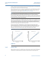
2.5.3 Set transmitter percent of range (transfer function) . . . . . . . . . . . . . . . . . .15
2.6 Configure for Level and Flow . . . . . . . . . . . . . . . . . . . . . . . . . . . . . . . . . . . . . . . . . . . .16
2.6.1 Configuring scaled variable. . . . . . . . . . . . . . . . . . . . . . . . . . . . . . . . . . . . . . . .16
Contents

ii
Reference Manual
00809-0100-4102, Rev AA
Table of Contents
May 2013
Table of Contents
2.6.2 Re-Mapping device variables . . . . . . . . . . . . . . . . . . . . . . . . . . . . . . . . . . . . . .18
2.6.3 Set range points . . . . . . . . . . . . . . . . . . . . . . . . . . . . . . . . . . . . . . . . . . . . . . . . .19
2.7 Review configuration data . . . . . . . . . . . . . . . . . . . . . . . . . . . . . . . . . . . . . . . . . . . . . .20
2.7.1 Review pressure information . . . . . . . . . . . . . . . . . . . . . . . . . . . . . . . . . . . . . .20
2.7.2 Review device information . . . . . . . . . . . . . . . . . . . . . . . . . . . . . . . . . . . . . . . .20
2.7.3 Review radio information . . . . . . . . . . . . . . . . . . . . . . . . . . . . . . . . . . . . . . . . .21
2.7.4 Review operating parameters . . . . . . . . . . . . . . . . . . . . . . . . . . . . . . . . . . . . .21
2.8 Configuring the LCD display. . . . . . . . . . . . . . . . . . . . . . . . . . . . . . . . . . . . . . . . . . . . .22
2.9 Detailed transmitter setup . . . . . . . . . . . . . . . . . . . . . . . . . . . . . . . . . . . . . . . . . . . . . .23
2.9.1 Configure process alerts . . . . . . . . . . . . . . . . . . . . . . . . . . . . . . . . . . . . . . . . . .23
2.9.2 Damping. . . . . . . . . . . . . . . . . . . . . . . . . . . . . . . . . . . . . . . . . . . . . . . . . . . . . . . .23
2.9.3 Write protect . . . . . . . . . . . . . . . . . . . . . . . . . . . . . . . . . . . . . . . . . . . . . . . . . . . .24
2.10Diagnostics and service . . . . . . . . . . . . . . . . . . . . . . . . . . . . . . . . . . . . . . . . . . . . . . . .24
2.10.1Device reset. . . . . . . . . . . . . . . . . . . . . . . . . . . . . . . . . . . . . . . . . . . . . . . . . . . . .25
2.10.2Join status. . . . . . . . . . . . . . . . . . . . . . . . . . . . . . . . . . . . . . . . . . . . . . . . . . . . . . .25
2.10.3Number of available neighbors . . . . . . . . . . . . . . . . . . . . . . . . . . . . . . . . . . . .26
2.11Advanced Functions for HART Protocol. . . . . . . . . . . . . . . . . . . . . . . . . . . . . . . . . . .27
2.11.1Saving, Recalling, and Cloning Configuration Data . . . . . . . . . . . . . . . . . . .27
3Section 3: Installation
3.1 Overview . . . . . . . . . . . . . . . . . . . . . . . . . . . . . . . . . . . . . . . . . . . . . . . . . . . . . . . . . . . . .29
3.2 Safety messages. . . . . . . . . . . . . . . . . . . . . . . . . . . . . . . . . . . . . . . . . . . . . . . . . . . . . . .29
3.2.1 Warnings (). . . . . . . . . . . . . . . . . . . . . . . . . . . . . . . . . . . . . . . . . . . . . . . . . . . . . .30
3.3 Considerations . . . . . . . . . . . . . . . . . . . . . . . . . . . . . . . . . . . . . . . . . . . . . . . . . . . . . . . .31
3.3.1 Installation considerations . . . . . . . . . . . . . . . . . . . . . . . . . . . . . . . . . . . . . . . .31
3.3.2 Wireless considerations. . . . . . . . . . . . . . . . . . . . . . . . . . . . . . . . . . . . . . . . . . .31
3.3.3 Mechanical considerations . . . . . . . . . . . . . . . . . . . . . . . . . . . . . . . . . . . . . . . .32
3.3.4 Environmental considerations . . . . . . . . . . . . . . . . . . . . . . . . . . . . . . . . . . . . .32
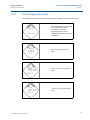
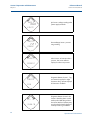
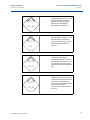
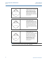
3.3.5 Draft range considerations . . . . . . . . . . . . . . . . . . . . . . . . . . . . . . . . . . . . . . . .33
3.4 Installation procedures . . . . . . . . . . . . . . . . . . . . . . . . . . . . . . . . . . . . . . . . . . . . . . . . .35
3.4.1 Mount the transmitter . . . . . . . . . . . . . . . . . . . . . . . . . . . . . . . . . . . . . . . . . . . .36
3.4.2 Impulse piping. . . . . . . . . . . . . . . . . . . . . . . . . . . . . . . . . . . . . . . . . . . . . . . . . . .41
3.4.3 Process connections. . . . . . . . . . . . . . . . . . . . . . . . . . . . . . . . . . . . . . . . . . . . . .43
3.4.4 Inline process connection . . . . . . . . . . . . . . . . . . . . . . . . . . . . . . . . . . . . . . . . .44
3.4.5 Power Module installation. . . . . . . . . . . . . . . . . . . . . . . . . . . . . . . . . . . . . . . . .45
3.4.6 Installing the LCD display . . . . . . . . . . . . . . . . . . . . . . . . . . . . . . . . . . . . . . . . .46
3.5 Rosemount 304, 305 and 306 integral manifolds . . . . . . . . . . . . . . . . . . . . . . . . . .47

iii
Reference Manual
00809-0100-4102, Rev AA
Table of Contents
May 2013
Table of Contents
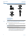
3.5.1 Rosemount 305 Integral Manifold installation procedure . . . . . . . . . . . . .48
3.5.2 Rosemount 306 Integral Manifold installation procedure . . . . . . . . . . . . .49
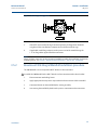
3.5.3 Rosemount 304 Conventional Manifold installation procedure . . . . . . . .50
3.5.4 Manifold operation. . . . . . . . . . . . . . . . . . . . . . . . . . . . . . . . . . . . . . . . . . . . . . .50
4Section 4: Commissioning
4.1 Overview . . . . . . . . . . . . . . . . . . . . . . . . . . . . . . . . . . . . . . . . . . . . . . . . . . . . . . . . . . . . .55
4.2 Safety messages. . . . . . . . . . . . . . . . . . . . . . . . . . . . . . . . . . . . . . . . . . . . . . . . . . . . . . .55
4.2.1 Warnings (). . . . . . . . . . . . . . . . . . . . . . . . . . . . . . . . . . . . . . . . . . . . . . . . . . . . . .56
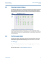
4.3 Viewing network status . . . . . . . . . . . . . . . . . . . . . . . . . . . . . . . . . . . . . . . . . . . . . . . .57
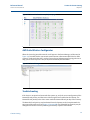
4.4 Verifying operation . . . . . . . . . . . . . . . . . . . . . . . . . . . . . . . . . . . . . . . . . . . . . . . . . . . .57
4.4.1 Using the Field Communicator. . . . . . . . . . . . . . . . . . . . . . . . . . . . . . . . . . . . .60
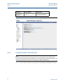
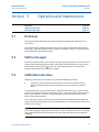
4.5 Configuring transmitter security. . . . . . . . . . . . . . . . . . . . . . . . . . . . . . . . . . . . . . . . .61
5Section 5: Operation and maintenance
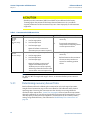
5.1 Overview . . . . . . . . . . . . . . . . . . . . . . . . . . . . . . . . . . . . . . . . . . . . . . . . . . . . . . . . . . . . .63
5.2 Safety messages. . . . . . . . . . . . . . . . . . . . . . . . . . . . . . . . . . . . . . . . . . . . . . . . . . . . . . .63
5.3 Calibration overview . . . . . . . . . . . . . . . . . . . . . . . . . . . . . . . . . . . . . . . . . . . . . . . . . . .63
5.3.1 Determining necessary Sensor Trims . . . . . . . . . . . . . . . . . . . . . . . . . . . . . . .64
5.3.2 Determining calibration frequency . . . . . . . . . . . . . . . . . . . . . . . . . . . . . . . . .65
5.3.3 Compensating for Span line pressure effects (range 4 and range 5). . . . .66
5.4 Trim the pressure signal . . . . . . . . . . . . . . . . . . . . . . . . . . . . . . . . . . . . . . . . . . . . . . . .67
5.4.1 Sensor Trim Overview . . . . . . . . . . . . . . . . . . . . . . . . . . . . . . . . . . . . . . . . . . . .67
5.4.2 Sensor Trim . . . . . . . . . . . . . . . . . . . . . . . . . . . . . . . . . . . . . . . . . . . . . . . . . . . . .68
5.4.3 Recall Factory Trim—Sensor Trim. . . . . . . . . . . . . . . . . . . . . . . . . . . . . . . . . . .70
5.4.4 Line Pressure Effect (Range 2 and Range 3) . . . . . . . . . . . . . . . . . . . . . . . . . .70
5.4.5 Compensating for Line Pressure (Range 4 and Range 5). . . . . . . . . . . . . . .70
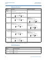
5.5 LCD Screen Messages . . . . . . . . . . . . . . . . . . . . . . . . . . . . . . . . . . . . . . . . . . . . . . . . . .73
5.5.1 Startup Screen Sequence . . . . . . . . . . . . . . . . . . . . . . . . . . . . . . . . . . . . . . . . .73
5.5.2 Diagnostic Button Screen Sequence . . . . . . . . . . . . . . . . . . . . . . . . . . . . . . . .75
5.5.3 Network Diagnostic Status Screens. . . . . . . . . . . . . . . . . . . . . . . . . . . . . . . . .76
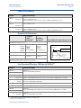
5.5.4 Device Diagnostic Screens . . . . . . . . . . . . . . . . . . . . . . . . . . . . . . . . . . . . . . . .79
6Section 6: Troubleshooting
6.1 Overview . . . . . . . . . . . . . . . . . . . . . . . . . . . . . . . . . . . . . . . . . . . . . . . . . . . . . . . . . . . . .83
6.2 Safety messages. . . . . . . . . . . . . . . . . . . . . . . . . . . . . . . . . . . . . . . . . . . . . . . . . . . . . . .83
6.2.1 Warnings (). . . . . . . . . . . . . . . . . . . . . . . . . . . . . . . . . . . . . . . . . . . . . . . . . . . . . .84
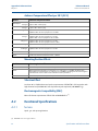
6.3 Removing from service . . . . . . . . . . . . . . . . . . . . . . . . . . . . . . . . . . . . . . . . . . . . . . . . .88

iv
Reference Manual
00809-0100-4102, Rev AA
Table of Contents
May 2013
Table of Contents
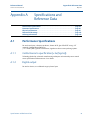
AAppendix A: Specifications and
Reference Data
A.1 Performance Specifications . . . . . . . . . . . . . . . . . . . . . . . . . . . . . . . . . . . . . . . . . . . . .89
A.1.1 Conformance to specification (±3s (Sigma)) . . . . . . . . . . . . . . . . . . . . . . . . .89
A.1.2 Digital output . . . . . . . . . . . . . . . . . . . . . . . . . . . . . . . . . . . . . . . . . . . . . . . . . . .89
A.2 Functional Specifications . . . . . . . . . . . . . . . . . . . . . . . . . . . . . . . . . . . . . . . . . . . . . . .92
A.2.1 Service. . . . . . . . . . . . . . . . . . . . . . . . . . . . . . . . . . . . . . . . . . . . . . . . . . . . . . . . . .92
A.2.2 Range and Sensor Limits . . . . . . . . . . . . . . . . . . . . . . . . . . . . . . . . . . . . . . . . . .93
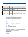
A.3 Wireless Self-Organizing Networks. . . . . . . . . . . . . . . . . . . . . . . . . . . . . . . . . . . . . . .93
A.3.1 Overpressure limits . . . . . . . . . . . . . . . . . . . . . . . . . . . . . . . . . . . . . . . . . . . . . .94
A.3.2 Static pressure limit . . . . . . . . . . . . . . . . . . . . . . . . . . . . . . . . . . . . . . . . . . . . . .95
A.3.3 Burst pressure limits. . . . . . . . . . . . . . . . . . . . . . . . . . . . . . . . . . . . . . . . . . . . . .95
A.3.4 Temperature limits. . . . . . . . . . . . . . . . . . . . . . . . . . . . . . . . . . . . . . . . . . . . . . .95
A.3.5 Humidity Limits. . . . . . . . . . . . . . . . . . . . . . . . . . . . . . . . . . . . . . . . . . . . . . . . . .96
A.3.6 Volumetric Displacement . . . . . . . . . . . . . . . . . . . . . . . . . . . . . . . . . . . . . . . . .96
A.3.7 Damping. . . . . . . . . . . . . . . . . . . . . . . . . . . . . . . . . . . . . . . . . . . . . . . . . . . . . . . .96
A.4 Physical specifications. . . . . . . . . . . . . . . . . . . . . . . . . . . . . . . . . . . . . . . . . . . . . . . . . .97
A.4.1 Electrical connections . . . . . . . . . . . . . . . . . . . . . . . . . . . . . . . . . . . . . . . . . . . .97
A.4.2 Process connections. . . . . . . . . . . . . . . . . . . . . . . . . . . . . . . . . . . . . . . . . . . . . .97
A.4.3 Process-Wetted parts. . . . . . . . . . . . . . . . . . . . . . . . . . . . . . . . . . . . . . . . . . . . .97
A.4.4 Rosemount 2051L Process Wetted Parts . . . . . . . . . . . . . . . . . . . . . . . . . . . .98
A.4.5 Non-Wetted Parts. . . . . . . . . . . . . . . . . . . . . . . . . . . . . . . . . . . . . . . . . . . . . . . .98
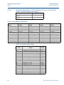
A.4.6 Shipping Weights for 2051 Wireless Pressure Transmitter. . . . . . . . . . . 100
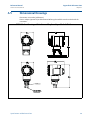
A.5 Dimensional Drawings . . . . . . . . . . . . . . . . . . . . . . . . . . . . . . . . . . . . . . . . . . . . . . . 101
A.6 Ordering Information . . . . . . . . . . . . . . . . . . . . . . . . . . . . . . . . . . . . . . . . . . . . . . . . 103
A.7 Options . . . . . . . . . . . . . . . . . . . . . . . . . . . . . . . . . . . . . . . . . . . . . . . . . . . . . . . . . . . . 127
A.8 Spare parts. . . . . . . . . . . . . . . . . . . . . . . . . . . . . . . . . . . . . . . . . . . . . . . . . . . . . . . . . . 130
BAppendix B: Product Certifications
B.1 Wireless Certifications. . . . . . . . . . . . . . . . . . . . . . . . . . . . . . . . . . . . . . . . . . . . . . . . 131
B.1.1 Approved manufacturing locations. . . . . . . . . . . . . . . . . . . . . . . . . . . . . . . 131
B.1.2 European directive information . . . . . . . . . . . . . . . . . . . . . . . . . . . . . . . . . . 131
B.1.3 Telecommunication compliance . . . . . . . . . . . . . . . . . . . . . . . . . . . . . . . . . 131
B.1.4 FCC and IC . . . . . . . . . . . . . . . . . . . . . . . . . . . . . . . . . . . . . . . . . . . . . . . . . . . . 131
B.1.5 Ordinary location certification for FM . . . . . . . . . . . . . . . . . . . . . . . . . . . . . 132
B.1.6 North American certifications . . . . . . . . . . . . . . . . . . . . . . . . . . . . . . . . . . . 132
B.1.7 CSA - Canadian Standards Association . . . . . . . . . . . . . . . . . . . . . . . . . . . . 132
B.1.8 European certifications . . . . . . . . . . . . . . . . . . . . . . . . . . . . . . . . . . . . . . . . . 132

v
Reference Manual
00809-0100-4102, Rev AA
Table of Contents
May 2013
Table of Contents
CAppendix C: Field Communicator Menu Trees and Fast Keys
C.1 Field Communicator menu trees. . . . . . . . . . . . . . . . . . . . . . . . . . . . . . . . . . . . . . . 135
DAppendix D: Network design best practices
D.1 Effective range . . . . . . . . . . . . . . . . . . . . . . . . . . . . . . . . . . . . . . . . . . . . . . . . . . . . . . 139

vi
Reference Manual
00809-0100-4102, Rev AA
Table of Contents
May 2013
Table of Contents

1
Reference Manual
00809-0100-4102, Rev AA
Section 1: Introduction
May 2013
Introduction
Section 1 Introduction
Using this manual . . . . . . . . . . . . . . . . . . . . . . . . . . . . . . . . . . . . . . . . . . . . . . . . . . . . . . . .page 1
Models covered . . . . . . . . . . . . . . . . . . . . . . . . . . . . . . . . . . . . . . . . . . . . . . . . . . . . . . . . . . page 1
Service support . . . . . . . . . . . . . . . . . . . . . . . . . . . . . . . . . . . . . . . . . . . . . . . . . . . . . . . . . . page 7
Product Recycling/Disposal . . . . . . . . . . . . . . . . . . . . . . . . . . . . . . . . . . . . . . . . . . . . . . . page 8
1.1 Using this manual
The sections in this manual provide information on installing, operating, and maintaining the
Rosemount 2051 Wireless pressure transmitter with WirelessHART
™
protocol. The sections are
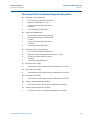
organized as follows:
Section 2: Configuration provides instruction on commissioning and operating 2051
Wireless transmitters. Information on software functions, configuration parameters,
and online variables is also included.
Section 3: Installation contains mechanical and electrical installation instructions.
Section 4: Commissioning contains techniques for properly commissioning the device.
Section 5: Operation and maintenance contains operation and maintenance
techniques.
Section 6: Troubleshooting provides troubleshooting techniques for the most common
operating problems.
Appendix A: Specifications and Reference Data supplies reference and specification
data, as well as ordering information.
Appendix B: Product Certifications contains approval information.
Appendix C: Field Communicator Menu Trees and Fast Keys provides full menu trees
and abbreviated fast key sequences for commissioning tasks.
Appendix D: Network design best practices provides information on how to optimize
network reliability and performance.
1.2 Models covered
The following Rosemount 2051 Pressure Transmitters are covered by this manual:
1.2.1 Rosemount 2051C Coplanar
™
Pressure Transmitter
Measures differential and gage pressure up to 2000 psi (137,9 bar).
Measures absolute pressure up to 4000 psi (275,8 bar)
1.2.2 Rosemount 2051T in-line Pressure Transmitter
Measures gage/absolute pressure up to 10000 psi (689,5 bar).

2
Reference Manual
00809-0100-4102, Rev AA
Section 1: Introduction
May 2013
Introduction
1.2.3 Rosemount 2051L Level Transmitter
Measures level and specific gravity up to 300 psi (20,7 bar)
1.2.4 Rosemount 2051CF Flowmeters
Measures flow in line sizes from
1
/2 in. (15 mm) to 96 in. (2400 mm)

3
Reference Manual
00809-0100-4102, Rev AA
Section 1: Introduction
May 2013
Introduction
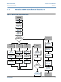
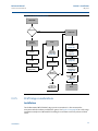
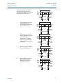
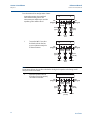
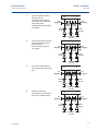
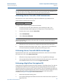
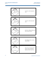
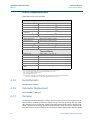
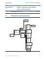
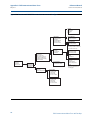
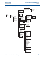
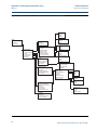
1.3 WirelessHART installation flowchart
Figure 1-1. WirelessHART installation flowchart
Yes
START HERE
Bench
Configuration
and Calibration
Field Install
No
Set Pressure to
PV
(
page 13)
Set Range
Points
(page 14)
Select Transfer
Function for
Percent of Range
(
page 15)
Verify
Apply Pressure
Yes
Within
Specifications?
No
Refer to
Section 5:
Operation and
maintenance
Mount
Transmitter
(
page 36)
Install Power
Module
(
page 13)
Trim the
Transmitter
(page 67)
Done
Review
Transmitter
Configuration
(
page 20)
Confirm
Transmitter
Configuration
(
page 20)
Configure for
Pressure
Configure
Scaled Variable
(
page 16)
Set Scaled
Variable to PV
(page 13)
Configure for
Level
Configure for
Flow
Configure
Scaled Variable
(
page 16)
Set Scaled
Variable to PV
(page 13)
Check Process
Connection
(
page 43)
Join Device to
Network by
Setting Network
ID and Join Key
(
page 12)
Configure
Update Rate
(page 12)
Set Device Tag
(
page 11)
Set Process
Variable Units
(page 13)
Set Range Points
(page 14)
Set Range Points
(page 14)

4
Reference Manual
00809-0100-4102, Rev AA
Section 1: Introduction
May 2013
Introduction
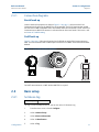
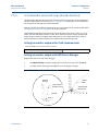
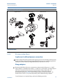
1.4 Transmitter overview
The Rosemount 2051C Coplanar design is offered for Differential Pressure (DP), Gage Pressure
(GP) and Absolute Pressure (AP) measurements. The Rosemount 2051C utilizes capacitance
sensor technology for DP and GP measurements. The Rosemount 2051T and 2051CA utilize
piezo-resistive sensor technology for AP and GP measurements.
The major components of the Rosemount 2051 Wireless transmitter are the sensor module and
the electronics housing. The sensor module contains the oil filled sensor system (isolating
diaphragms, oil fill system, and sensor) and the sensor electronics. The sensor electronics are
installed within the sensor module and include a temperature sensor, a memory module, and
the analog to digital signal converter (A/D converter). The electrical signals from the sensor
module are transmitted to the output electronics in the electronics housing. The electronics
housing contains the output electronics board, the antenna, and the battery. The basic block
diagram of the Rosemount 2051CD Wireless device is illustrated in Figure 1-3 on page 5.
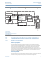
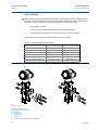
For the Rosemount 2051, pressure is applied to the isolating diaphragm(s). The oil deflects the
sensor which then changes its capacitance or voltage signal. This signal is then changed to a
digital signal by the Signal Processing Module. The microprocessor then takes the signals from
the Signal Processing Module and calculates the correct output of the transmitter. This signal is
then sent via wireless communication to the Gateway.
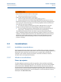
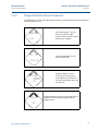
An optional LCD can be ordered that connects directly to the output electronics board which
maintains direct access to the signal terminals. The display indicates output and abbreviated
diagnostic messages. A clear display cover is provided. For WirelessHART output, the LCD
Display features a three-line display. The first line describes the process variable measured, the
second line displays the measured value, and the third line displays engineering units. The LCD
can also display diagnostics messages.
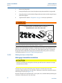
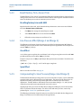
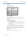
Note
LCD Display utilizes a 3-line, 7-digit character display and can display output and diagnostic
messages. See Figure 1-2.
Figure 1-2. LCD Display
LCD Display

5
Reference Manual
00809-0100-4102, Rev AA
Section 1: Introduction
May 2013
Introduction
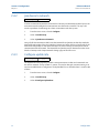
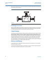
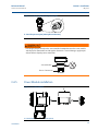
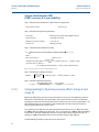
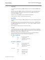
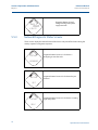
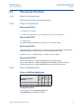
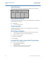
Figure 1-3. Block diagram of operation
A. Sensor Module
B. Electronics Board
C. WirelessHART Signal to Control System
D. Field Communicator
1.5 Considerations before transmitter installation
1.5.1 Wireless considerations
Power up sequence
The Power Module should not be installed on any wireless device until the Smart Wireless
Gateway is installed and functioning properly. This transmitter uses the Green Power Module
(order model number 701PGNKF). Wireless devices should also be powered up in order of
proximity from the Smart Wireless Gateway, beginning with the closest. This will result in a
simpler and faster network installation. Enable Active Advertising on the Gateway to ensure that
new devices join the network faster. For more information, see the Smart Wireless Gateway
Manual (Doc. No. 00809-0200-4420).
Antenna position
The internal antenna is designed for multiple mounting orientations. The transmitter should be
mounted according to best practices for your pressure measurement application.
ABC
D
Signal Processing
Tem p.
Sensor
Sensor Module
Memory
Microprocessor
Sensor linearization
Rerange
Diagnostics
Engineering units
Communication
Memory
Configuration
Local HART
Handheld
Communicator
WirelessHART
Communication

6
Reference Manual
00809-0100-4102, Rev AA
Section 1: Introduction
May 2013
Introduction
Network design best practices
When mounting the device, recommended practices should be considered to achieve the best
wireless performance. See Appendix D: Network design best practices for more information on
recommended practices.
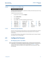
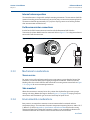
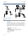
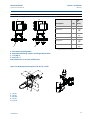
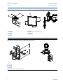
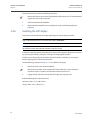
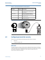
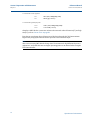
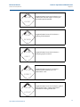
Field communicator connections
The Power Module needs to be installed in the device for the Field Communicator to interface
with the Rosemount 2051. The Field Communicator connections are located on the Power
Module. To communicate to the transmitter, connect the Field Communicator to the COMM
port connections on the Power Module. This transmitter uses the Green Power Module; please
order model number 701PGNKF. Field communication with this device requires a HART-based
Field Communicator using the correct Rosemount 2051 Wireless DD. The Power Module is
keyed and can only be inserted in one orientation. Refer to Figure 1-4 for instructions on
connecting the Field Communicator to the 2051.
Figure 1-4. Field Communicator Connections
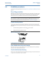
1.5.2 Mechanical
Location
When choosing an installation location and position, take into account access to the power
module compartment for easy power module replacement.
Electronics cover
The electronics cover is tightened so that polymer contacts polymer. When removing the
electronics cover, ensure that there is no damage done to the o-ring. If damaged replace before
reattaching cover, ensuring polymer contacts polymer (i.e. no o-ring visible).
1.5.3 Electrical
Power module
The Rosemount 2051 Wireless Pressure Transmitter is self-powered. The Power Module
contains a primary lithium-thionyl chloride battery (Green Power Module, model number

7
Reference Manual
00809-0100-4102, Rev AA
Section 1: Introduction
May 2013
Introduction
701PGNKF). Each battery contains approximately 5 grams of lithium. Under normal conditions,
the battery materials are self-contained and are not reactive as long as the battery and the
Power Module are maintained. Care should be taken to prevent thermal, electrical, or
mechanical damage. Contacts should be protected to prevent premature discharge.
Use caution when handling the Power Module, it may be damaged if dropped from heights in
excess of 6.10 m (20 ft).
1.5.4 Environmental
Verify that the operating atmosphere of the transmitter is consistent with the appropriate
hazardous locations certifications.
Temperature effects
The transmitter will operate within specifications for ambient temperatures between -40 and 85
°C (-40 and 185 °F).
Heat from the process is transferred to the transmitter housing. If the process temperature is
high, the ambient temperature will need to be lower to account for heat transferred to the
transmitter housing. See “Process Temperature Limits” on page 96 for process temperature
derating.
1.6 Service support
Within the United States, call the Emerson Process Management Instrument and Valve
Response Center using the 1-800-654-RSMT (7768) toll-free number. This center, available 24
hours a day, will assist you with any needed information or materials.
The center will ask for product model and serial numbers, and will provide a Return Material
Authorization (RMA) number. The center will also ask for the process material to which the
product was last exposed.
For inquiries outside of the United States, contact the nearest Emerson Process Management
representative for RMA instructions.
To expedite the return process outside of the United States, contact the nearest Emerson
Process Management representative.
Individuals who handle products exposed to a hazardous substance can avoid injury if they
are informed of and understand the hazard. The product being returned will require a copy
of the required Material Safety Data Sheet (MSDS) for each substance must be included
with the returned goods.

8
Reference Manual
00809-0100-4102, Rev AA
Section 1: Introduction
May 2013
Introduction
The Power Module contains a primary lithium-thionyl chloride battery (Green Power Module,
model number 701PGNKF). Each Power Module contains approximately 5 grams of lithium.
Under normal conditions, the Power Module materials are self-contained and are not reactive as
long as the batteries and the module integrity are maintained. Care should be taken to prevent
thermal, electrical or mechanical damage. Contacts should be protected to prevent premature
discharge. Power Module hazards remain when cells are discharged.
Power Module should be stored in a clean and dry area. For maximum battery life, storage
temperature should not exceed 86 °F (30 °C).
Emerson Process Management Instrument and Valve Response Center representatives will
explain the additional information and procedures necessary to return goods exposed to
hazardous substances.
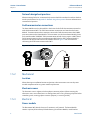
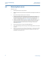
1.7 Product Recycling/Disposal
Recycling of equipment and packaging should be taken into consideration and disposed of in
accordance with local and national legislation/regulations.
Shipping considerations for wireless products (Lithium Batteries: Green Power Module,
model number 701PGNKF):
The unit was shipped to you without the Power Module installed. Please remove the Power
Module from the unit prior to shipping.
Each power module contains a primary lithium-thionyl chloride battery. Primary lithium
batteries are regulated in transportation by the U.S. Department of Transportation, and are
also covered by IATA (International Air Transport Association), ICAO (International Civil
Aviation Organization), and ARD (European Ground Transportation of Dangerous Goods). It
is the responsibility of the shipper to ensure compliance with these or any other local
requirements. Please consult current regulations and requirements before shipping.
Page is loading ...
Page is loading ...
Page is loading ...
Page is loading ...
Page is loading ...
Page is loading ...
Page is loading ...
Page is loading ...
Page is loading ...
Page is loading ...
Page is loading ...
Page is loading ...
Page is loading ...
Page is loading ...
Page is loading ...
Page is loading ...
Page is loading ...
Page is loading ...
Page is loading ...
Page is loading ...
Page is loading ...
Page is loading ...
Page is loading ...
Page is loading ...
Page is loading ...
Page is loading ...
Page is loading ...
Page is loading ...
Page is loading ...
Page is loading ...
Page is loading ...
Page is loading ...
Page is loading ...
Page is loading ...
Page is loading ...
Page is loading ...
Page is loading ...
Page is loading ...
Page is loading ...
Page is loading ...
Page is loading ...
Page is loading ...
Page is loading ...
Page is loading ...
Page is loading ...
Page is loading ...
Page is loading ...
Page is loading ...
Page is loading ...
Page is loading ...
Page is loading ...
Page is loading ...
Page is loading ...
Page is loading ...
Page is loading ...
Page is loading ...
Page is loading ...
Page is loading ...
Page is loading ...
Page is loading ...
Page is loading ...
Page is loading ...
Page is loading ...
Page is loading ...
Page is loading ...
Page is loading ...
Page is loading ...
Page is loading ...
Page is loading ...
Page is loading ...
Page is loading ...
Page is loading ...
Page is loading ...
Page is loading ...
Page is loading ...
Page is loading ...
Page is loading ...
Page is loading ...
Page is loading ...
Page is loading ...
Page is loading ...
Page is loading ...
Page is loading ...
Page is loading ...
Page is loading ...
Page is loading ...
Page is loading ...
Page is loading ...
Page is loading ...
Page is loading ...
Page is loading ...
Page is loading ...
Page is loading ...
Page is loading ...
Page is loading ...
Page is loading ...
Page is loading ...
Page is loading ...
Page is loading ...
Page is loading ...
Page is loading ...
Page is loading ...
Page is loading ...
Page is loading ...
Page is loading ...
Page is loading ...
Page is loading ...
Page is loading ...
Page is loading ...
Page is loading ...
Page is loading ...
Page is loading ...
Page is loading ...
Page is loading ...
Page is loading ...
Page is loading ...
Page is loading ...
Page is loading ...
Page is loading ...
Page is loading ...
Page is loading ...
Page is loading ...
Page is loading ...
Page is loading ...
Page is loading ...
Page is loading ...
Page is loading ...
Page is loading ...
Page is loading ...
Page is loading ...
Page is loading ...
Page is loading ...
Page is loading ...
Page is loading ...
-
 1
1
-
 2
2
-
 3
3
-
 4
4
-
 5
5
-
 6
6
-
 7
7
-
 8
8
-
 9
9
-
 10
10
-
 11
11
-
 12
12
-
 13
13
-
 14
14
-
 15
15
-
 16
16
-
 17
17
-
 18
18
-
 19
19
-
 20
20
-
 21
21
-
 22
22
-
 23
23
-
 24
24
-
 25
25
-
 26
26
-
 27
27
-
 28
28
-
 29
29
-
 30
30
-
 31
31
-
 32
32
-
 33
33
-
 34
34
-
 35
35
-
 36
36
-
 37
37
-
 38
38
-
 39
39
-
 40
40
-
 41
41
-
 42
42
-
 43
43
-
 44
44
-
 45
45
-
 46
46
-
 47
47
-
 48
48
-
 49
49
-
 50
50
-
 51
51
-
 52
52
-
 53
53
-
 54
54
-
 55
55
-
 56
56
-
 57
57
-
 58
58
-
 59
59
-
 60
60
-
 61
61
-
 62
62
-
 63
63
-
 64
64
-
 65
65
-
 66
66
-
 67
67
-
 68
68
-
 69
69
-
 70
70
-
 71
71
-
 72
72
-
 73
73
-
 74
74
-
 75
75
-
 76
76
-
 77
77
-
 78
78
-
 79
79
-
 80
80
-
 81
81
-
 82
82
-
 83
83
-
 84
84
-
 85
85
-
 86
86
-
 87
87
-
 88
88
-
 89
89
-
 90
90
-
 91
91
-
 92
92
-
 93
93
-
 94
94
-
 95
95
-
 96
96
-
 97
97
-
 98
98
-
 99
99
-
 100
100
-
 101
101
-
 102
102
-
 103
103
-
 104
104
-
 105
105
-
 106
106
-
 107
107
-
 108
108
-
 109
109
-
 110
110
-
 111
111
-
 112
112
-
 113
113
-
 114
114
-
 115
115
-
 116
116
-
 117
117
-
 118
118
-
 119
119
-
 120
120
-
 121
121
-
 122
122
-
 123
123
-
 124
124
-
 125
125
-
 126
126
-
 127
127
-
 128
128
-
 129
129
-
 130
130
-
 131
131
-
 132
132
-
 133
133
-
 134
134
-
 135
135
-
 136
136
-
 137
137
-
 138
138
-
 139
139
-
 140
140
-
 141
141
-
 142
142
-
 143
143
-
 144
144
-
 145
145
-
 146
146
-
 147
147
-
 148
148
-
 149
149
-
 150
150
-
 151
151
-
 152
152
-
 153
153
-
 154
154


Emerson 2051 Wireless Pressure User manual
- Category
- Measuring, testing & control
- Type
- User manual
- This manual is also suitable for
Ask a question and I''ll find the answer in the document
Finding information in a document is now easier with AI
Related papers
-
Emerson 3051S Specification
-
-
-
-
Rosemount 5408 and 5408:SIS Level User manual
-
-
-
-
-
Other documents
-
 Ivy Terrace IVS114-1-11NT Installation guide
-
-
-
TPI 608 Owner's manual
-
-
Emerson Process Management 2051 User manual
-
-
Omega PX725A Owner's manual
-
-
