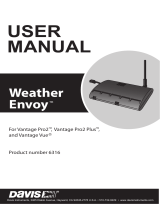
DAVIS Weather Box (6260) Owner's manual
- Category
- Weather stations
- Type
- Owner's manual
This manual is also suitable for

3465 Diablo Ave., Hayward, CA 94545 USA
sWWW.davisnet.com
®
Weather Box
Sensor Suite
Weather Envoy™
WeatherLinkIP™


1
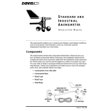
Weather Box User Guide
Weather Box has everything you need to quickly get your weather data onto your
computer, the web, and your smartphone. It includes a Vantage Vue® wireless
Integrated Sensor Suite (ISS), which collects outside weather data. The ISS sends the
data wirelessly to the included Weather Envoy via a powerful, frequency-hopping,
spread-spectrum radio. The ISS is solar powered and includes a battery back-up. From
the Envoy, the data can be downloaded to your computer via the included
WeatherLinkIP data logger, which also uploads it automatically to your page on
WeatherLink.com. Your data is always accessible via the Internet or a smartphone app.
Follow these steps to begin enjoying your weather data.
• Assemble the Vantage Vue ISS
• Connect the Weather Envoy
• Log on to WeatherLink.com
• Download the Mobile App
• Install & Configure WeatherLink Software
• Mount the ISS
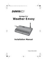
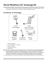
Included Components and Hardware
Vantage Vue
Integrated
Sensor Suite
Wind Vane
Tipping Spoon
Assembly
Wind Cups
Weather Envoy
WeatherLinkIP Data
Logger (installed)
AC Power
Adapter
Ethernet Cable
WeatherLink CD
Debris Screen

2
Hardware
Note: If any of the hardware components are missing or not included, contact Customer Service toll free
at 1-800-678-3669 about receiving replacement hardware or other components.
Assemble the Vantage Vue ISS
The Vantage Vue ISS contains a rain collector, temperature/humidity sensor,
anemometer, and wind vane. The temperature/humidity sensor is mounted in a passive
radiation shield to minimize the impact of solar radiation on sensor readings. The
anemometer measures wind speed, and the wind vane measures wind direction.
The radio transmitter is housed within the ISS. It collects outside weather data from the
ISS sensors and transmits that data to the Weather Envoy.
Note: Your Vantage Vue ISS can transmit to a Vantage Vue or Vantage Pro2 console. You can purchase
one or more consoles to use in different rooms.
Prepare the ISS for Installation
It is best to prepare the ISS for installation inside, near your computer so that you can
easily verify data from the ISS before final installation.
Tools Needed
• Adjustable wrench or 7/16” (11 mm) wrench
• Compass or local area map
Note: Use a clean, well-lit work table or work area to prepare the ISS for installation.
1. Attach the wind cups to the anemometer.
2. Attach the wind vane.
3. Install the rain collector tipping spoon assembly.
4. Install the debris screen in the rain collector.
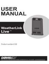
5. Install the ISS battery to apply power.
Backing plate
U-Bolt
1/4” lock washers
1/4” hex nuts
#6 x 1” Pan Head Screws
0.05” Allen wrench
3-Volt lithium battery
Debris screen
Battery cover with
thumbscrew
1

3
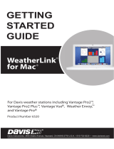
Attach the Wind Cups to the Anemometer
The Vantage Vue anemometer measures wind speed. The wind cups are mounted on the
anemometer shaft on the top of the ISS assembly.
1. Gently slide the wind cup assembly
down onto the anemometer’s
stainless steel shaft as far as it will
go, as shown.
2. Use the Allen wrench provided to
tighten the set screw near the top of
the center hub of the wind cups, as
shown. Ensure that the set screw is
screwed in fully and is tight.
3. Pull gently on the hub to ensure that
the wind cups are securely fastened
to the shaft.
4. Spin the wind cups to make sure they
spin freely.
Note: If the wind cups don’t spin freely, loosen the set screw, remove them from the shaft, and repeat
the wind cup installation process.
Attach the Wind Vane
The Vantage Vue wind vane measures wind direction. The wind vane is mounted on a
stainless steel shaft on the bottom of the ISS assembly.
1. Hold the ISS assembly on its side
with the anemometer and radiation
shields on your left, the wind vane
shaft on your right and the wind
cups away from you.
2. When the ISS is held in this manner,
the wind vane shaft is horizontal,
and will orient itself so that its flat
side will be facing to the right, as
shown.
3. Holding the ISS assembly with your
left hand, grasp the wind vane with
your right hand so that the
“arrowhead” end is pointed down.
4. Gently slide the wind vane onto the wind vane shaft, rotating the wind vane slightly
left and right if necessary, until the end of the shaft is visible and protrudes
slightly from the bottom surface of the wind vane.
5. Secure the wind vane to the shaft by firmly tightening the wind vane set screw with
the Allen wrench provided.
Install cups onto
stainless steel shaft.
Tighten set screw
with Allen wrench.

4
Install the Rain Collector Tipping Spoon Assembly
1. Locate the tipping spoon assembly cavity on the underside of the ISS Base.
2. Insert the wider end of the tipping spoon assembly into the slot first, sliding it under
the raised lip of the slot.
3. Fit the narrow end into the slot and tighten the thumbscrew securely.
Install the Debris Screen
The Vantage Vue ISS rain collector debris screen captures debris that may otherwise
clog your rain collector.
1. Locate the small black plastic ISS debris screen in your hardware package.
The debris screen has four small tabs that hold it in place in the base of the rain
collector.
2. Holding the ISS assembly with one hand, and holding the debris screen by the top,
press it into the opening in the rain collector until the tabs snap into the opening.
Install the Battery
The Vantage Vue ISS stores energy from the solar panel for power at night. A 3-volt
lithium battery provides a backup power source. The battery compartment is located on
the underside of the ISS base. The compartment cover is included in the hardware
packet.
To install the ISS backup battery.
1. Insert the 3-volt lithium battery into the ISS battery compartment, being sure to match
the “+” sign on the battery with the “+” sign embossed on the inside of the battery
compartment.
2. Ensure that the battery is properly in place, install the battery compartment cover, and
tighten the thumbscrew. The green LED transmitter will light, then begin to flash
every 2.5 seconds to show transmission of a data packet. This flashing will stop
within a few minutes to conserve battery life.

5
Connect the Weather Envoy
Prepare the Weather Envoy
• Connect the Weather Envoy to your local computer
• Install AC power source
• Install optional batteries
• Mount your Envoy
• Connect Envoy to WeatherLink software
• Set up the Envoy using WeatherLink software
Connect Weather Envoy to Local Computer
Note: When connecting the Ethernet cable from the Envoy to the router, it is important that the Envoy
has no power, either from the AC connector or batteries.
1. Connect one end of the Ethernet cable to the WeatherLinkIP data logger.
2. Locate a free Ethernet port on your broadband or DSL router and connect the cable to
the port.
Note: Be sure to connect the Ethernet cable BEFORE powering up the Envoy with the AC Adapter or
batteries.
3. Connect AC power adapter. Insert the power adapter plug into the power jack on the
end of the Envoy case. It’s next to the data logger output cable. Plug the adapter into
the electrical socket.
Note: An Envoy using a WeatherLinkIP data logger requires use of the AC-power adapter. Battery
power can be used for short-term backup power in the event of a power outage, but an Envoy
with WeatherLinkIP should use the AC-power adapter as its main source of power.
The Weather Envoy beeps two times, occurring within one second of each other. On
power-up, the IP data logger will negotiate its connection with the router.
4. Write down the Device ID and Key located on the side of the WeatherLinkIP data
logger for further use.
The Device ID (DID) and Key uniquely identify your data logger on the WeatherLink
Network (www.weatherlink.com). They are both required to create a login on
WeatherLink.com and are used to connect the WeatherLinkIP data logger to the
software.
Because WeatherLinkIP is continuously uploading current weather information to the
www.weatherlink.com, leave the WeatherLinkIP and Envoy connected to your router at
all times.
2

6
Install Backup Batteries
The Weather Envoy is supplied with an AC power adapter. You should install batteries
to act as backup power. Batteries will provide enough power to operate for less than one
day.
1. Find the battery cover on the back side of the Envoy case.
2. Remove the battery cover by
pressing on the arrow
embossed on the cover and
sliding the cover away from
the case.
3. Insert three AA-cell batteries,
negative terminal (flat side)
first. Replace the battery cover
on the case.
Optional: Adding an External Temperature Probe
Your wireless Weather Envoy has a built-in temperature-humidity sensor as well as the
barometer. The temperature and humidity are reported as “Inside Temperature” and
“Inside Humidity.”
You may replace the built-in temperature-humidity sensor with an external temperature
probe with a 25’ (7.6 m) cable, which can be used to measure the temperature of air,
water, or soil. The External Temperature Probe with RJ connector comes in two models:
6475 (with stainless steel probe) or 6477 (with durable plastic probe).
Simply plug the RJ connector of the
temperature probe into the RJ jack
on the bottom of the Envoy.
External
Temperature
Sensor
RJ
Connector
RJ
Jack

7
Mount Your Weather Envoy
You can place your Envoy on your desktop or install it on a wall near your router.
Envoy Location
You should place the Envoy in a location where it is easily accessible and can be easily
connected to a router. For more accurate readings, follow these suggestions:
• Avoid placing the Envoy in direct sunlight. This may cause erroneous inside temperature
and humidity readings and may damage the unit.
• Avoid placing the Envoy near radiators or heating/air conditioning ducts.
• If you are mounting the Envoy on a wall, choose an interior wall. Avoid exterior walls
that tend to heat up or cool down depending on the weather.
The range of the radio transmission that the Envoy can receive from the wireless ISS
depends on several factors. Try to position the Envoy as close to the transmitting
weather station as possible for best results.
Typical maximum ranges are:
• Line of sight: 1000 feet (300 m).
• Under most conditions: 200 - 400 feet (60 - 120 m).
Other range and transmission considerations include:
• Range may be reduced by walls, ceilings, trees, foliage, a metal roof or other large metal
structures or objects such as aluminum siding, metal ducts, and metal appliances, such as
refrigerators.
• Transmission between wireless units may be obscured by something unidentifiable, or by
some obstacle that can’t be worked around.
Note: For best results, orient the ISS antenna and the Envoy antenna so that the orientation and angles
of the antennas are parallel to each other.
For better reception over greater distances or for weaker signals, consider using a
Wireless Repeater (#7626 or 7627) or Long-Range Repeaters (# 7654) to strengthen the
signal or increase the distance between your ISS and the Weather Envoy.

8
Wall Mounting the Envoy
1. Use the provided wall mounting template as an example of hole spacing and
alignment when installing your Envoy.
2. Use the template as a guideline for the hole
markings on the wall where you want to mount
the Envoy, and use a pencil to mark the location
for the two mounting screws.
The screws should be 3.25
'' (82.5 mm) apart and
lined up vertically.
3. Drill the marked locations with a 3/32
'' or 7/64''
(2.2 to 2.7 mm) drill bit.
4. Drive the two #6 x 1
'' (3.5 mm x 25 mm) pan
head self-threading screws into the wall.
5. Leave at least a 1/8
'' (3 mm) space between the
wall and the heads of the screws.
6. Slide the keyholes on the back of the case over
the two screw heads.
Log On to WeatherLink.com and
Verify Data From the ISS
Once you have connected the WeatherLinkIP data logger to your router, the data logger
starts uploading your current weather data to your page on the WeatherLink Network. To
see your weather data over the Internet:
1. Go to www.weatherlink.com
2. Click Register, then click “Register with WeatherLinkIP.”
3. Read the license agreement and register your account using the Device ID and Key
information provided on the data logger.
4. Create your account.
5. To view your current weather data on the web, click the My Weather tab at the top of
the page. Within a few minutes you should see your weather data online. (Anytime
you want to see your current data go to www.weatherlink.com/user/<username>.)
Download the Mobile App
Download the free WeatherLink Mobile App to see your station’s data on
your smartphone. Search for WeatherLink on iTunes or the Google Play Store.
3.25"
(82.55mm)
Drill 3/32"
or 7/64"
(~2.2 to 2.7mm)
Holes
3
4

9
Install and Configure
WeatherLink Software
Install the Software
Follow the steps below to install the WeatherLink software.
1. Place the WeatherLink software CD in your CD ROM drive.
The install program should start automatically. If the install program does not start,
select Run from the Start menu, type D:\SETUP (or the correct letter for your CD
ROM drive), and click OK to begin the installation.
2. Click Accept to install the necessary components.
The License Agreement dialog box displays.
3. Review the license agreement, click I agree and click Next. The Choose Destination
Location dialog box displays.
4. Select the default location to install WeatherLink or find another location by clicking
Browse.
Note: If you are upgrading your software from a previous version, click Browse to search for the
directory or folder of the previous version of WeatherLink.
5. Choose whether to make WeatherLink available to anyone who uses that computer or
just yourself. Click Next. The Confirm Installation dialog box displays.
6. Click Next to start the installation. The Installing WeatherLink dialog box displays
the installation progress. The Installation Successful dialog box displays once the
software installation has been completed.
7. Click OK. WeatherLink has been installed successfully.
5

10
Configure WeatherLink Software
Walk through the following procedures to setup and configure your WeatherLink
software and the connection to your Weather Envoy.
Running the Software
To run the software, double-click the WeatherLink icon. If no stations have been
assigned in the program directory, the software prompts you to add a station (see below
for details).
If this is a software upgrade and if there is more than one station in the program
directory when the application opens, the last station that was displayed is automatically
opened.
Station Setup
The software includes a station setup “Walkthrough” that steps you through the weather
station configuration procedures. After adding a new station, the Walkthrough dialog
box automatically displays. By selecting Yes , Walkthrough begins. By selecting No, the
Walkthrough is canceled.
You can set up and configure your station by separately selecting all of the necessary
setup options from the Setup menu. A Walkthrough option is included in the Setup
menu which allows you to access the Walkthrough at any time.
During the Walkthrough process, the software displays a series of dialog boxes. At each
step in the Walkthrough process, confirmation boxes are provided to perform or skip the
next step in the Walkthrough. To continue, select OK. To skip this step and move to the
next step, select Skip. To cancel the entire Walkthrough process, select Cancel.
Note: Please refer to the WeatherLink Online Help for more information about the complete
Walkthrough process.
Communication Port Settings
WeatherLink contains a dialog box for configuring the communication channel for your
WeatherLinkIP data logger. Use the Communications Port dialog box to select the
communications type and to test communication between the computer and the station.
1. Select Communications Port from the Setup menu or use the Walkthrough to
display the dialog box.
The Communications Port dialog box displays.
2. Select TCP/IP from the Communications field.

11
3. Select one of the three available radio buttons that best describes the type of TCP/IP
connection you want to setup:
• Local Device ID — Connects to the WeatherLinkIP data logger through a Local
Area Network connection. Use this option if your computer is on the same subnet
as your WeatherLinkIP data logger.
• Remote IP Address — Connects the WeatherLinkIP data logger and station to
the WeatherLink Software through a remote connection using an IP address. This
connection generally requires a static IP address.
Note: This option is only used if your WeatherLinkIP-equipped Envoy is at a location on the Internet that
is remote from the location of the computer on which your are running your WeatherLink
software. It is an advanced setup option. See the WeatherLink Online Help for more information.
• Web Download — Downloads archived data that has been automatically
uploaded to WeatherLink.com.
For a Local Connection:
1. Click Local Device ID.
2. Click Find to find the Device ID for the data logger.
3. Click Test to verify communication.
4. Click OK to save the Communications Port settings.
For Web Download:
1. Click Web Download.
Note: Choosing Web Download inactivates functions that require communication with the Envoy.
2. Enter the user ID and password you created on www.weatherlink.com.
3. Click OK to save the Web Download settings.
Set Transceiver
Your Weather Envoy is set at the factory to “listen” to the ISS with ID 1. Since the
transmitter ID of your ISS has also been factory set to ID 1, you should not have to
change this setting. However, if you do change the ISS ID, use the Set Transceiver
dialog box to change your Weather Envoy to the “listen” to the new ID.
Note: This dialog box is the only available tool for configuring the transmitter ID and repeater ID settings
on your Weather Envoy.
To set transceiver options:
1. Select Set Transceiver from the Setup menu; the dialog box displays.
Select a Station Type for each of the possible eight transmitter IDs the Envoy may be
receiving. See the WeatherLink Online Help System for more information on
configuring the stations, the retransmit feature and configuring the Envoy for using
repeaters.

12
Mount the ISS
Choosing a Location for the ISS
To ensure that the Vantage Vue weather station performs at its best, use these guidelines
to select the optimum mounting location for the ISS. Be sure to take into consideration
ease of access for maintenance and wireless transmission range when siting the station.
Note: When selecting a location for installing your ISS, especially on a rooftop, make sure it is a location
far from power lines. Seek professional help if you are uncertain about the safety of your
installation.
ISS Installation Guidelines
Note: These siting guidelines reflect an ideal condition. Rarely is it possible to create the perfect
installation. The better the siting, the more accurate your data will be.
• Place the ISS away from sources of heat such as chimneys, heaters, air conditioners and
exhaust vents.
• Place the ISS at least 100' (30 m) away from any asphalt or concrete roadway that readily
absorbs and radiates heat from the sun. Avoid installations near fences or sides of
buildings that receive a lot of sun during the day.
• Install the ISS as level as possible to ensure accurate rain and wind measurements. Use
the built in bubble level on the top of the ISS, just above the solar panel, to make sure the
ISS is level.
• In the Northern Hemisphere, the solar panel should face south for maximum sun
exposure.
• In the Southern Hemisphere, the solar panel should face north for maximum sun
exposure.
Note: If you install the ISS with the solar panel pointing in a direction other than south, you will need to
use the wind direction calibration function in the WeatherLink software in order to obtain accurate
wind direction readings.
6
SOUTH
(In the Northern
Hemisphere)
NORTH
(In the Southern
Hemisphere)

13
• Ideally, mount the ISS so that it is between 5’ (1.5 m) and 7’ (2.1 m) above the ground in
the middle of a gently sloping or flat, regularly mowed grassy or naturally landscaped
area that drains well when it rains. You can also mount the ISS on the roof, between 5’
(1.5 m) and 7’ (2.1 m) above the roof surface. For areas with average maximum yearly
snow depths over 3’ (0.9 m), mount the ISS at least 2’ (0.6 m) above this depth.
• Never install the ISS where it will be directly sprayed by a sprinkler system.
• Avoid installations near bodies of water such as swimming pools or ponds.
• Do not locate the ISS under tree canopies or near the sides of buildings that create “rain
shadows.” For heavily forested areas, site the ISS in a clearing or meadow.
• Site the ISS in a location with good sun exposure throughout the day.
• For agricultural applications:
• Install the ISS so that it is between 5’ (1.5 m) and 7’ (2.1 m) above the ground and
in the middle of the farm between similar crop types (i.e. two orchards, two
vineyards, or two row crops), if possible.
• Avoid areas exposed to extensive or frequent applications of agricultural
chemicals (which can degrade the sensors).
• Avoid installation over bare soils. The ISS performs best when installed over
well-irrigated, regularly mowed grass
• If the last three guidelines cannot be met, install the ISS at the edge of the primary
crop of interest.
Important: Once you have chosen your location, test the transmission distance to the
Envoy by temporarily placing the ISS at the site and making sure new data appears on
WeatherLink.com. (You can do this on your smartphone if you have downloaded the
mobile app.) Remember that new data uploads every minute on WeatherLink.com, so
data will not appear instantly. Refresh your browser (F5) to see the latest data.
Siting guidelines that may affect the anemometer
• For optimal wind data, mount the ISS so that the wind cups are at least 7’ (2.1 m) above
obstructions such as trees or buildings that may obstruct wind flow.
• For optimal wind data, you may mount the ISS on a roof, keeping in mind ease of access
to the ISS for maintenance and safety considerations. Ideally, mount it so that the wind
cups are at least 7’ (2.1 m) above the roof apex.
• The standard for meteorological and aviation applications is to place the anemometer 33’
(10 m) above the ground. Seek professional help for this such installation.
Note: For roof mounting, and ease of installation, we recommend using the optional tripod (#7716). For
other installations, use the Mounting Pole Kit (#7717).
Note: For more detailed siting suggestions, see Application Note: Reporting Quality Observations to
NOAA on the Davis Weather Support section on www.davisnet.com.

14
Install the ISS
The Vantage Vue ISS can only be mounted on the top of a pole or rod. You will use the
U-bolt and associated nuts and washers that are included with your ISS mounting
hardware package to install the ISS on a pole. (See “Hardware” on page 2.)
Note: A mounting pole is not included with your Vantage Vue ISS and must be purchased separately,
either from Davis Instruments or from your local hardware retailer.
Recommended Accessories for Pole Mounting
• Use the Mounting Tripod (#7716) for easiest mounting.
• Use the Mounting Pole Kit (#7717) to raise the installation height of the ISS by up to
37.5" (0.95 m).
General Guidelines for Installing on a Pole
• With the supplied U-bolt, the ISS can be mounted on a pole or rod having an outside
diameter ranging from 1" to 1.75" (25 – 44 mm).
• To mount on a smaller pole, obtain a U-bolt that fits the base openings but that has a
longer threaded section. If mounting the ISS on a smaller pole with the included U-bolt,
the threaded sections of the U-bolt will be too short to securely mount the ISS.
Installing the ISS on a Pole
1. If you are mounting your ISS on a Davis Mounting Tripod or the pole included with a
Davis Mounting Pole Kit, follow the instructions included with those Davis products for
proper installation.
If you are not using one of these Davis products, mount on a galvanized steel pole having
an outside diameter ranging from 1" to 1.75" (25 – 44 mm).
Note: It is important that the mounting pole be plumb. You may wish to use a level such as a magnetic
”torpedo level” to assure that the ISS, when mounted on top of the pole, will be level.
2. Using the illustration above as a guide, hold the ISS so that the wind cups and
radiation shield are on the left and gently place the ISS on top of the pole.
C-Shaped
Bracket

15
3. While holding the mounting base of the ISS against the pole, place the two ends of the
U-bolt around the pole and through the two holes in the C-shaped bracket on the base.
4. Slide the metal backing plate over the bolt ends where they extend out from the far side of
the bracket.
5. Secure the backing plate with a lock washer and hex nut on each of the bolt ends, as
shown in the illustration.
6. Tighten the hex nuts with your fingers only so that the ISS is just secure enough on
the pole for you to release your grip.
7. If you are in the Northern Hemisphere, rotate the ISS on the pole so that the solar panel is
facing true south; if you are in the Southern Hemisphere, rotate the ISS so that the solar
panel is facing true north. The more precisely the solar panels face due south or north, the
more accurate your wind direction readings will be. If you cannot install your ISS so that
the solar panel faces true south, you will need to calibrate the wind direction. See
“Calibrate Wind Direction (if necessary)” on page 16.
Note: Do not rely on a compass unless it is properly calibrated. In North America there can be up to 15°
variation between true north and a magnetic north compass reading.
8. When the ISS is properly oriented, tighten the hex nuts with a wrench. Do not exceed
96 inch-pounds (10.8 newton-meters) of torque.
Note: Refer to the bubble level on the top of the ISS to make sure it is as level as possible.

16
Finishing the Installation
Clearing Data Collected During Testing and Installation
Now that the ISS is mounted outside, any data that was collected during testing and mounting
should be cleared.
To clear all the collected data:
1. Run WeatherLink software.
2. Select Clear from the Setup menu.
3. The Clear dialog box will appear.
4. Choose Check All, then click OK to clear all the data.
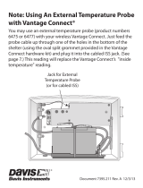
Calibrate Wind Direction (if necessary)
The wind vane is calibrated at the factory to be accurate when the solar panel is pointing
true south. If you are in the Southern Hemisphere or anywhere where your ISS cannot be
installed with the solar panel facing south, you must calibrate the wind direction
readings in WeatherLink software.
1. Open WeatherLink.
2. In the Setup menu, choose Set Wind.
3. The Set Wind dialog box displays. Under “Calibration,” three values appear. The
first, “Raw Reading,” shows the current wind direction in degrees, if the solar panel
faced true south. The middle, “Adjusted Reading” can be edited. The last,
“Calculated Offset” is automatically generated using the raw and adjusted values.
Calibrate your wind direction by entering a value in the Adjusted Reading that causes
the correct Calculated Offset (Raw - Adjusted = Calculated Offset). For example:
• If the solar panel faces due north: Calculated Offset should be 180.
(Add 180 to the Raw Reading value, subtract 360 if the total is more than 360.)
• If the solar panel faces due east: Calculated Offset should be 270.
(Add 270 to the Raw Reading value, subtract 360 if the total is more than 360.)
• If the solar panel faces due west: Calculated Offset should be 90.
(Add 90 to the Raw Reading value, subtract 360 if the total is more than 360.)
94
180
274
Example of calibrating an ISS with Solar Panel facing true north.

17
Maintenance and Troubleshooting
Vantage Vue ISS
Maintenance
Cleaning the Radiation Shield
The outer surface of the radiation shield should be cleaned when there is excessive dirt and
build-up on the plates. Use a damp cloth to clean the outer edge of each ring.
Note: Spraying down or using water excessively to clean the radiation shield can damage the sensitive
sensors or alter the data the ISS is transmitting.
Check the radiation shield for debris or insect nests at least once a year and clean when
necessary. A buildup of material inside the shield reduces its effectiveness and may cause
inaccurate temperature and humidity readings.
1. Using a Phillips head screwdriver, loosen the
two #6 x 2
1
/
2
” screws holding the five
radiation shield plates together, as shown.
2. Taking care to maintain the order in which the
five plates are assembled, separate the plates as
shown and remove all debris from inside the
shield.
3. Reassemble the plates in the same order in
which they were disassembled, and fasten them
together using a Phillips head screwdriver to
tighten the #6 x 2
1
/
2
” screws, as shown.
Cleaning the Rain Collector, Debris Screen, and Tipping Spoon Module
To maintain accuracy, thoroughly clean the rain collector cone and debris screen as needed or
at least once a year.
Note: Cleaning the rain collector and tipping spoon may cause false rain readings. See “Clearing Data
Collected During Testing and Installation” on page 16.
1. Use a damp, soft cloth to remove any debris from the rain collector and debris screen.
2. Use pipe cleaners to clear any debris remaining in the screen.
Solid plates,
drain holes
toward
mounting pole.

18
3. When all parts are clean, rinse with clear water.
To clean the tipping spoon assembly, it must first be removed from the ISS base.
1. Unscrew the thumbscrew securing the tipping spoon
assembly to the ISS base. Slide the assembly down
and away from the base.
2. Use a damp, soft cloth to gently remove any debris
from the tipping spoon assembly, being careful not
to damage any moving parts or scratch the spoon
surface.
3. When all parts are clean, rinse with clear water, and
replace the assembly. See “Install the Rain Collector
Tipping Spoon Assembly” on page 4.
Troubleshooting
The Transmitter ID LED on the ISS did not light after I installed the battery.
Press and release the white transmitter ID pushbutton next to the battery
compartment.
If the light still does not come on after pressing the transmitter pushbutton, there may
be a problem with the ISS transmitter. Call Technical Support.
If, after pressing the Transmitter Pushbutton, the Transmitter ID LED flashes every
2.5 seconds (indicating transmission) but your Envoy isn’t picking up a signal
anywhere in the room, it could be related to one of the following causes:
• You changed the ISS Transmitter ID at the ISS or Envoy, but not at both.
• Reception is being disrupted by frequency interference from outside sources, or the dis-
tance and barriers are too great.
Note: Interference has to be strong to prevent the Envoy from receiving a signal while in the same room
as the ISS.
• There is a problem with the Envoy.
If a problem with receiving the wireless transmission still exists, please contact
Technical Support.
The data is not what I expect.
Comparing data from your ISS to measurements from TV, radio, newspapers, or a
neighbor is NOT a valid method of verifying your readings. Readings can vary
considerably over short distances. How you site the ISS can also make a big difference.
If you have questions, contact Davis Technical Support.
Page is loading ...
Page is loading ...
Page is loading ...
Page is loading ...
-
 1
1
-
 2
2
-
 3
3
-
 4
4
-
 5
5
-
 6
6
-
 7
7
-
 8
8
-
 9
9
-
 10
10
-
 11
11
-
 12
12
-
 13
13
-
 14
14
-
 15
15
-
 16
16
-
 17
17
-
 18
18
-
 19
19
-
 20
20
-
 21
21
-
 22
22
-
 23
23
-
 24
24


DAVIS Weather Box (6260) Owner's manual
- Category
- Weather stations
- Type
- Owner's manual
- This manual is also suitable for
Ask a question and I''ll find the answer in the document
Finding information in a document is now easier with AI
Related papers
-
DAVIS Vantage Pro/Pro2 Wind Cup Replacement (7905) Owner's manual
-
-
-
DAVIS Vantage VUE Owner's manual
-
-
DAVIS WeatherLink Owner's manual
-
DAVIS 6555 Owner's manual
-
-
DAVIS 6100 User manual
-
Other documents
-
AcuRite Wind Cups for AcuRite Atlas Weather Sensor User manual
-
 SEAV LG 2183 GB User guide
-
Davis Instruments Vantage VUE Installation guide
-
 Davis Instruments 6316C User manual
-
 Davis Instruments 6314 Owner's manual
-
 Davis Instruments 6520 Quick start guide
-
 Davis Instruments 6620 Owner's manual
-
 Davis Instruments 7911 Installation guide
-
 Davis Instruments 6510SER Owner's manual
-
 Davis Instruments 6100 Owner's manual


