Page is loading ...

GordonRay
®
BH
The Economical, Unitary Infrared Heater
Submittal: BH Series
Job:
Location:
Engineer:
Gas Specs:
Date:
QTY. MODEL NO. BH UNIT INPUT BTU/HR
QTY. MODEL NO. BH UNIT INPUT BTU/HR
QTY. MODEL NO. BH UNIT INPUT BTU/HR
QTY. MODEL NO. BH UNIT INPUT BTU/HR
TOTAL INPUT BTU/HR
Important
Before installation and operation of heating equipment, read and understand the
Installation, Operation and Service Manual.
Applications, engineering and detailed guidance on systems design, installation and product performance is available upon request.
ROBERTS GORDON
®
products are to be installed only in accordance with local laws, codes and regulations, and only by a contractor qualified in
the installation and service of gas-fired heating equipment.
Roberts-Gordon Roberts-Gordon
1250 William Street 76 Main Street West, Unit 10
P.O. Box 44 Grimsby, Ontario L3M 1R6
Buffalo, New York 14240-0044 Canada
Telephone: 716.852.4400 Telephone: 905.945.5403
Fax: 716.852.0854 Fax: 905.945.0511
Toll Free: 800.828.7450
www.rg-inc.com
© Copyright 2004 Roberts-Gordon P/N170601NA Rev D 07/04

© 2004
All rights reserved. No part of this work covered by the copyrights herein may be reproduced
or copied in any form or by any means - graphic, electronic, or mechanical, including
photocopying, recording, taping or information storage and retrieval systems - without the
written permission of Roberts-Gordon.
TABLE OF CONTENTS
STANDARD PARTS LIST............................................. 1
Contents of BH-Series Burner Carton .....................1
Contents of Core and Extension Packages.............1
GENERAL SPECIFICATIONS ......................................2
Material Specification .............................................. 2
Reflectors................................................................2
Heater Specifications...............................................2
Ignition .....................................................................2
Suspension Specifications....................................... 2
Controls Specifications............................................2
Gas Pressure at Manifold........................................ 2
Pipe Connection...................................................... 2
Dimensions..............................................................2
Gas Inlet Pressure...................................................2
Electrical Rating (all models)................................... 2
CLEARANCES TO COMBUSTIBLES .......................... 3
Standard Reflector...................................................3
One Side Reflector.................................................. 3
Two Side Reflectors ................................................ 3
45° Tilt Reflector......................................................4
U-Tube, Standard Reflector.....................................4
U-Tube, Full 45°......................................................4
U-Tube, Opposite 45° Reflector .............................. 5
2-Foot Deco Grille, 1-Foot Deco Grille
and Protective Grille ................................................ 5
Lower Clearance Shield ..........................................5
Venting .................................................................... 6
BH-SERIES ASSEMBLY OVERVIEW.......................... 7
Major Component Descriptions...............................7
BH-Series Linear Assembly Overview ....................8
HEATER INSTALLATION.............................................9
Critical Hanger Placement....................................... 9
BH-Series Linear Layout Overview ........................10
BH-Series Linear Layout Overview (Continued)......11
Burner Tube Installation ..........................................11
Tube Clamp Package Installation............................ 12
Coupling and Tube Assembly..................................12
Coupling and Tube Assembly (Continued)..............13
Turbulator Installation.............................................. 14
Reflector Installation................................................14
Reflector, U-Clip and Reflector Support
Installation ............................................................... 15
Burner Installation....................................................16
OPTIONAL HEATER ACCESSORIES..........................17
BH-Series U-Tube Assembly Overview ..................17
BH-Series U-Tube Layout Overviews ..................... 18
BH-Series U-Tube Layout Overviews (Continued) ..19
Elbow Package Configuration .................................20
Elbow Installation.....................................................20
Elbow Installation (continued)..................................20
Reflector Joint Installation........................................20
Reflector Joint Detail................................................21
REFLECTOR SIDE EXTENSION..................................22
Bracket Installation...................................................22
Side Reflector Installation........................................22
LOWER CLEARANCE SHIELD INSTALLATION.........23
Shield Support Strap Assembly...............................23
TWO-FOOT DECORATIVE GRILLE INSTALLATION..23
Grille Installation......................................................23
Frame Shield Installation.........................................24
Reflector Side Extension Installation ......................24
ONE-FOOT DECORATIVE GRILLE INSTALLATION..25
One-Foot Decorative Grille Bracket.........................25
Decorative Grille......................................................25
Joint Piece and Reinforcement................................25
End Piece and Reflector End Cap...........................26
90° Elbow.................................................................26
PROTECTIVE GRILLE INSTALLATION.......................27
Silicone Cap Installation...........................................27
Grille End Cap Installation .......................................27
Grille Installation......................................................27
VENTING........................................................................28
Horizontal Ventilation 4" (10 cm) Pipe .....................28
Vertical Ventilation 4" (10 cm) Pipe..........................28
Common Sidewall Venting.......................................29
Common Vertical Venting .......................................30
OUTSIDE COMBUSTION AIR SUPPLY.......................31
Vertical Outside Air Supply for
Single Heater Installation.........................................31
Horizontal Outside Air Supply for
Single Heater Installation.........................................31
Vertical Outside Air Supply for
Double Heater Installation........................................32
Horizontal Outside Air Supply for
Double Heater Installation........................................32
GAS PIPING...................................................................33
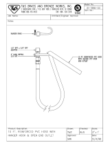
Gas Connection with Stainless Steel
Flex Connector.........................................................33
WIRING..........................................................................34
Line Voltage Thermostat Wiring...............................34
Low Voltage Thermostat Wiring...............................35
BH-Series Internal Wiring ........................................36
BH-Series Ladder Diagram......................................36
Electrical Connection to the Burner .........................37
INTERNAL BURNER DIAGRAM...................................38
THE ROBERTS GORDON
®
GORDONRAY
®
BH
LIMITED WARRANTY...................................................39
Printed in U.S.A.

ROBERTS GORDON
®
BH-SER I ES SUBMITTAL SHEET
© 2004 Roberts-Gordon
BEFORE IN STALLATION AND OPER ATION OF HEATING E QUIPMENT, READ AND U NDERSTAND THE INSTALLATION, OPERATIO N AND SERVICE MANUAL.
APPLICATION S, ENGI NEERING AND DETAILED GUID ANCE ON SYSTEMS DESIGN, INSTAL LATION AND PRODUCT PERFORMANCE IS AVAILABLE UPON RE QUEST. ROBERTS GORDON
®
PRODUCTS ARE TO BE
INSTALLED ONLY IN ACCORDANCE WI TH L OCAL LAWS, CODES AND REGULATIONS, AND ONLY BY A CONTRACTOR QUALI FIE D IN THE INST ALLATION AND SE RVICE OF GAS-FIRED HEATING EQUI PME NT.
STANDARD PARTS LIST
Contents of BH-Series Burner Carton
Part No. Description BH-40 BH-60 BH-80 BH-100 BH-115 BH-125 BH-140 BH-150 BH-175 BH-200
071XXXXX BH-Series Burner (Rate and Fuel Varies) 1 1 1 1 1 1 1 1 1 1
90709700 Blower Assembly with Cord 1 1 1 1 1 1 1 1 1 1
02568200 Gasket (Burner to Burner Tube) 1 1 1 1 1 1 1 1 1 1
90709801 Gasket (Blower to Burner) 1 1 1 1 1 1 1 1 1 1
170101NA Installation Manual 1 1 1 1 1 1 1 1 1 1
91201708 Pipe Nipple (Black) 1/2” x 4” 1 1 1 1 1 1 1 1 1 1
94273914 Hex Head Rolok 5/16 - 18 4 4 4 4 4 4 4 4 4 4
96411600 Split Lock washer 4 4 4 4 4 4 4 4 4 4
91412200 Flexible Gas Connector Assembly, 1/2” NPT 1 1 1 1 1 1 - - - -
91412203 Flexible Gas Connector Assembly, 3/4" NPT - - - - - - 1 1 1 1
91907302 S-Hooks 2 2 2 2 2 2 2 2 2 2
91911700 Outside Air Collar 1 1 1 1 1 1 1 1 1 1
94118106 #8 x 3/8 Hex Washer Head (for Outside Air Collar) 3 3 3 3 3 3 3 3 3 3
92311800 Keps Nut 4 4 4 4 4 4 4 4 4 4
03051503 Turbulator Adapter 1 1 1 1 1 - 1 - - -
03051504 Turbulator 2.5’ (76 cm), Aluminized Steel 2 4 4 1 3 - 1 - - -
03051505 Turbulator 2.5’ (76 cm), Stainless Steel 1 - - - - - - - - -
Contents of Core and Extension Packages
Core Packages Extension Packages
Hot Rolled Aluminized Hot Rolled Aluminized
Part No. Description
20
'
(6m)
30
'
(9m)
40
'
(12m)
10
'
(3m)
20
'
(6m)
30
'
(9m)
40
'
(12m)
10
'
(3m)
20
'
(6 m )
30
'
(9 m )
40
'
(1 2m )
10
'
(3m)
20
'
(6m )
30
'
(9m)
40
'
(12m)
91409300
Tube, Hot Rolled Steel, 10
'
(3m)
123----1234----
91409408
Tube, HT Aluminized, 10
'
(3m)
----123----1234
03051101
Burner Tube, ALUMI-THERM
®
Steel, 10
'
(3m)
111-111--------
03051601
Burner Tube, HT ALUMI-THERM
®
Steel, 10
'
(3m)
---1-----------
01312700 Coupling Assembly 1 2 3 - 1 2 3 12341234
02750303
Standard Reflector, 8
'
(3.5m)
346234623462346
02750800 End Cap 2222222-- ------
03090100 Tube and Reflector Hanger 345234512341234
91907302 S-Hook 345234512341234
03050010 Reflector Support Package (Strap, Wire Form, Screws) 235123523462346
91107720 U-Clip Package 111111111111111
90502700 Vent Adapter 1111111-- ------
01318901 Tube Clamp Package 1111111-- ------
Part Number
CP20HRS
CP30HRS
CP40HRS
CP10ALUM
CP20ALUM
CP30ALUM
CP40ALUM
EXP10HRS
EXP20HRS
EXP30HRS
EXP40HRS
EXP10ALUM
EXP20ALUM
EXP30ALUM
EXP40ALUM

ROBERTS GORDON
®
BH-SER I ES SUBMITTAL SHEET
© 2004 Roberts-Gordon
BEFORE IN STALLATION AND OPER ATION OF HEATING E QUIPMENT, READ AND U NDERSTAND THE INSTALLATION, OPERATIO N AND SERVICE MANUAL.
APPLICATION S, ENGI NEERING AND DETAILED GUID ANCE ON SYSTEMS DESIGN, INSTAL LATION AND PRODUCT PERFORMANCE IS AVAILABLE UPON RE QUEST. ROBERTS GORDON
®
PRODUCTS ARE TO BE
INSTALLED ONLY IN ACCORDANCE WI TH L OCAL LAWS, CODES AND REGULATIONS, AND ONLY BY A CONTRACTOR QUALI FIE D IN THE INST ALLATION AND SE RVICE OF GAS-FIRED HEATING EQUI PME NT.
GENERAL SPECIFICATIONS
Material Specification
Reflectors
.024 Aluminum
Heater Specifications
Ignition
Fully automatic spark ignition with safety shut-off.
Suspension Specifications
Hang heater with materials with a minimum working
load of 75 lbs (33 kg).
Controls Specifications
Time switches, thermostats, etc. can be wired into
the electrical supply. External controls supplied as an
optional extra.
General Specifications for BH-Series heaters are as follows:
Gas Pressure at Manifold:
Natural Gas: 3.5" w.c.
LP Gas: 10.5" w.c.
Pipe Connection:
1/2" NPT (for BH-40, 60, 80, 100, 115 & 125)
3/4" NPT (for BH- 140, 150,175 & 200)
Dimensions:
Vent Connection Size: 4" (10 cm)
Outside Air Connection Size: 4" (10 cm)
Refer to figure above for dimensional information.
Gas Inlet Pressure:
Natural Gas:
for BH-40, 60, 80, 100,
115, 125, 140, 150 4.6" w.c. Minimum
for BH-175, 200 5.0" w.c. Minimum
14.0" w.c. Maximum
LP Gas: 11.0" w.c. Minimum
14.0" w.c. Maximum
Electrical Rating (all models):
120V - 60 Hz., 1.0 Amp
Turbulator (select models)
Side View
Reflector
12.5
(32 cm)
End View
11
(28 cm)
Maximum or Minimum Length A
Burner Tube
12.5
(32 cm)
Heat Input
Rate
Length “A”
Recommended
Minimum Mounting Height*
Model (BTUH X1000) Minimum Maximum Space Spot
BH-40 40 10’ (3m) 10’ (3m) 8'-10' (2.4 - 3m) 8' (2.4m)
BH-60 60 20' (6m) 20' (6m) 10'-12' (3 - 3.6m) 9' (2.7m)'
BH-80 80 20' (6m) 30' (9m) 12'-15' (3.6 - 4.5m) 11' (3.3m)
BH-100 100 30' (9m) 40' (12m) 12'-15' (3.6 - 4.5m) 12' (3.7m)
BH-115 115 30' (9m) 50' (15m) 15'-20’ (4.5 - 6m) 15' (4.6m)
BH-125 125 40' (12m) 50' (15m) 15'-20’ (4.5 - 6m) 15' (4.6m)
BH-140 140 40' (12m) 60' (18m) 20'-25’ (6 - 7.6m) 20' (6.1m)
BH-150 150 50' (15m) 60' (18m) 20'-25’ (6 - 7.6m) 20' (6.1m)
BH-175 175 50' (15m) 70' (21m) 25' (7.6m) 23' (7m)
BH-200 200 60' (18m) 80' (24m) 25' (7.6m) 25' (7.6m)

ROBERTS GORDON
®
BH-SER I ES SUBMITTAL SHEET
© 2004 Roberts-Gordon
BEFORE IN STALLATION AND OPER ATION OF HEATING E QUIPMENT, READ AND U NDERSTAND THE INSTALLATION, OPERATIO N AND SERVICE MANUAL.
APPLICATION S, ENGI NEERING AND DETAILED GUID ANCE ON SYSTEMS DESIGN, INSTAL LATION AND PRODUCT PERFORMANCE IS AVAILABLE UPON RE QUEST. ROBERTS GORDON
®
PRODUCTS ARE TO BE
INSTALLED ONLY IN ACCORDANCE WI TH L OCAL LAWS, CODES AND REGULATIONS, AND ONLY BY A CONTRACTOR QUALI FIE D IN THE INST ALLATION AND SE RVICE OF GAS-FIRED HEATING EQUI PME NT.
CLEARANCES TO COMBUSTIBLES
NOTE: 1. All dimensions are from the surfaces of all tubes, couplings and elbows.
2. Clearances B, C and D can be reduced by 50% after 25' (7.5 m) of tubing downstream
from where the burner and burner tube connect.
3. “-” indicates an unapproved application. Roberts-Gordon prohibits the installation of
this heater for all unapproved applications.
Standard Reflector
(inches) (centimeters)
Model ABCDABCD
BH-40 6 27 52 27 16 69 133 69
BH-60 6 35 62 35 16 89 158 89
BH-80 6 38 65 38 16 97 166 97
BH-100 6 40 70 40 16 102 178 102
BH-115/125 6 46 76 46 16 117 194 117
BH-140/150 6 50 79 50 16 127 201 127
BH-175/200 8 52 82 52 21 133 209 133
C
BD
A
One Side Reflector
(inches) (centimeters)
Model ABCDABCD
BH-40 6 9 52 44 16 23 133 112
BH-60 6 9 62 47 16 23 158 120
BH-80 6 9 69 54 16 23 176 138
BH-100 6 9 76 59 16 23 194 150
BH-115/125 6 9 82 65 16 23 209 166
BH-140/150 6 9 85 69 16 23 216 176
BH-175/200 8 9 88 73 21 23 224 186
C
BD
A
Two Side Reflectors
(inches) (centimeters)
Model ABCDABCD
BH-40 6 15 52 15 16 39 133 39
BH-60 6 23 65 23 16 59 166 59
BH-80 6 25 71 25 16 64 181 64
BH-100 6 27 77 27 16 69 196 69
BH-115/125 6 32 83 32 16 82 211 82
BH-140/150 6 35 87 35 16 89 221 89
BH-175/200 8 40 91 40 21 102 232 102
C
BD
A

ROBERTS GORDON
®
BH-SER I ES SUBMITTAL SHEET
© 2004 Roberts-Gordon
BEFORE IN STALLATION AND OPER ATION OF HEATING E QUIPMENT, READ AND U NDERSTAND THE INSTALLATION, OPERATIO N AND SERVICE MANUAL.
APPLICATION S, ENGI NEERING AND DETAILED GUID ANCE ON SYSTEMS DESIGN, INSTAL LATION AND PRODUCT PERFORMANCE IS AVAILABLE UPON RE QUEST. ROBERTS GORDON
®
PRODUCTS ARE TO BE
INSTALLED ONLY IN ACCORDANCE WI TH L OCAL LAWS, CODES AND REGULATIONS, AND ONLY BY A CONTRACTOR QUALI FIE D IN THE INST ALLATION AND SE RVICE OF GAS-FIRED HEATING EQUI PME NT.
NOTE: 1. All dimensions are from the surfaces of all tubes, couplings and elbows.
2. Clearances B, C and D can be reduced by 50% after 25' (7.5 m) of tubing
downstream from where the burner and burner tube connect.
3. “-” indicates an unapproved application. Roberts-Gordon prohibits the installation
of this heater for all unapproved applications.
45° Tilt Reflector
(inches) (centimeters)
Model ABCDABCD
BH-40 8 8 50 46 21 21 127 117
BH-60 8 8 59542121150138
BH-80 8 8 65 60 21 21 166 153
BH-100 10 8 73 64 26 21 186 163
BH-115/125 10 8 77 69 26 21 196 176
BH-140/150 12 8 83 74 31 21 211 188
BH-175/200 12 8 85 79 31 21 216 201
C
BD
A
U-Tube, Standard Reflector
(inches) (centimeters)
Model ABCDABCD
BH-40 - - - - - - - -
BH-60 6 35 62 30 16 89 158 77
BH-80 6 38 68 37 16 97 173 94
BH-100 6 40 75 39 16 102 191 100
BH-115/125 6 46 78 43 16 117 199 110
BH-140/150 6 50 83 47 16 127 211 120
BH-175/200 8 54 87 51 21 138 221 130
B
D
C
A
U-Tube, Full 45°
(inches) (centimeters)
Model ABCDABCD
BH-40 - - - - - - - -
BH-60 8 8 59422121150107
BH-80 8 8 65 46 21 21 166 117
BH-100 8 8 73 52 21 21 186 133
BH-115/125 8 8 77 61 21 21 196 155
BH-140/150 8 8 83 66 21 21 211 168
BH-175/200 8 8 85 70 21 21 216 178
C
D
B
A

ROBERTS GORDON
®
BH-SER I ES SUBMITTAL SHEET
© 2004 Roberts-Gordon
BEFORE IN STALLATION AND OPER ATION OF HEATING E QUIPMENT, READ AND U NDERSTAND THE INSTALLATION, OPERATIO N AND SERVICE MANUAL.
APPLICATION S, ENGI NEERING AND DETAILED GUID ANCE ON SYSTEMS DESIGN, INSTAL LATION AND PRODUCT PERFORMANCE IS AVAILABLE UPON RE QUEST. ROBERTS GORDON
®
PRODUCTS ARE TO BE
INSTALLED ONLY IN ACCORDANCE WI TH L OCAL LAWS, CODES AND REGULATIONS, AND ONLY BY A CONTRACTOR QUALI FIE D IN THE INST ALLATION AND SE RVICE OF GAS-FIRED HEATING EQUI PME NT.
NOTE: 1. All dimensions are from the surfaces of all tubes, couplings and elbows.
2. Clearances B, C and D can be reduced by 50% after 25' (7.5 m) of tubing downstream
from where the burner and burner tube connect.
3. “-” indicates an unapproved application. Roberts-Gordon prohibits the installation of
this heater for all unapproved applications.
*When installed in the first 20’ (6 m).
U-Tube, Opposite 45° Reflector
(inches) (centimeters)
Model ABCDABCD
BH-40 - - - - - - - -
BH-60 8 54 59 22 21 138 150 56
BH-80 8 60 65 22 21 153 166 56
BH-100 10 64 73 22 26 163 186 56
BH-115/125 10 70 77 22 26 178 196 56
BH-140/150 12 74 83 22 31 188 211 56
BH-175/200 12 76 85 22 31 194 216 56
B
A
C
D
2-Foot Deco Grille, 1-Foot Deco Grille and Protective Grille
(inches) (centimeters)
Model ABCDABCD
BH-40 6 27 52 27 16 69 133 69
BH-60 6 35 62 35 16 89 158 89
BH-80 6 38 65 38 16 97 166 97
BH-100 6 40 70 40 16 102 178 102
BH-115/125 6 46 76 46 16 117 194 117
BH-140/150 6 50 79 50 16 127 201 127
BH-175/200 8 52 82 52 21 133 209 133
C
BD
A
Lower Clearance Shield*
(inches) (centimeters)
Model ABCDABCD
BH-40 6 34 27 34 16 87 69 87
BH-60 6 39 33 39 16 100 84 100
BH-80 6 40 38 40 16 102 97 102
BH-100 6 50 44 50 16 127 112 127
BH-115/125 6 54 48 54 16 138 122 138
BH-140/150 6 55 50 55 16 140 127 140
BH-175/200 - - - - - - - -
C
BD
A

ROBERTS GORDON
®
BH-SER I ES SUBMITTAL SHEET
© 2004 Roberts-Gordon
BEFORE IN STALLATION AND OPER ATION OF HEATING E QUIPMENT, READ AND U NDERSTAND THE INSTALLATION, OPERATIO N AND SERVICE MANUAL.
APPLICATION S, ENGI NEERING AND DETAILED GUID ANCE ON SYSTEMS DESIGN, INSTAL LATION AND PRODUCT PERFORMANCE IS AVAILABLE UPON RE QUEST. ROBERTS GORDON
®
PRODUCTS ARE TO BE
INSTALLED ONLY IN ACCORDANCE WI TH L OCAL LAWS, CODES AND REGULATIONS, AND ONLY BY A CONTRACTOR QUALI FIE D IN THE INST ALLATION AND SE RVICE OF GAS-FIRED HEATING EQUI PME NT.
NOTE: 1. All dimensions are from the surfaces of all tubes, couplings and elbows.
2. Clearances B, C and D can be reduced by 50% after 25' (7.5 m) of tubing downstream
from where the burner and burner tube connect.
3. “-” indicates an unapproved application. Roberts-Gordon prohibits the installation of
this heater for all unapproved applications.
Venting
(inches) (centimeters)
Model A E F A E F
BH-40 14 18 18 36 46 46
BH-60 141818364646
BH-80 20 24 18 51 61 46
BH-100 20 24 18 51 61 46
BH-115/125 20 24 18 51 61 46
BH-140/150 20 30 18 51 77 46
BH-175/200 20 30 18 51 77 46
Infrared Tubes
Vent
Pipes
Unvented
Vented
A
E
F

ROBERTS GORDON
®
BH-SER I ES SUBMITTAL SHEET
© 2004 Roberts-Gordon
BEFORE IN STALLATION AND OPER ATION OF HEATING E QUIPMENT, READ AND U NDERSTAND THE INSTALLATION, OPERATIO N AND SERVICE MANUAL.
APPLICATION S, ENGI NEERING AND DETAILED GUID ANCE ON SYSTEMS DESIGN, INSTAL LATION AND PRODUCT PERFORMANCE IS AVAILABLE UPON RE QUEST. ROBERTS GORDON
®
PRODUCTS ARE TO BE
INSTALLED ONLY IN ACCORDANCE WI TH L OCAL LAWS, CODES AND REGULATIONS, AND ONLY BY A CONTRACTOR QUALI FIE D IN THE INST ALLATION AND SE RVICE OF GAS-FIRED HEATING EQUI PME NT.
BH-SERIES ASSEMBLY OVERVIEW
Major Component Descriptions
Burner with Tube Gasket
Must be installed with the
flame observation window
facing down.
Reflector (Aluminum or
Stainless Steel)
Alternate overlap as shown on
overview. Minimum overlap is
7” (18 cm).
Tube and Reflector Hanger
with Clamp Package
Position this hanger no more
than 4” (10 cm) away from
the burner.
Coupling Assembly with Lock
Reflector End Cap
Punch out center section to
accommodate heat exchanger
tube.
Tube and Reflector Hanger
Suspend system from these
hangers.
Flex Gas Line with
Shut Off Cock
Tube
Hot Rolled or Heat Treated
Aluminized Tube supplied in
10’ (3 m) lengths.
Burner Tube
Supplied in 10
' (3 m) lengths.
Burner tube is always the first
tube after the burner.
Reflector Support Strap &
Wire Form
Turbulator
Turbulator must be installed in the
last standard section of tube.
Turbulator is not required on the
BH-125/150/175/200.
Vent Adapter

ROBERTS GORDON
®
BH-SER I ES SUBMITTAL SHEET
© 2004 Roberts-Gordon
BEFORE IN STALLATION AND OPER ATION OF HEATING E QUIPMENT, READ AND U NDERSTAND THE INSTALLATION, OPERATIO N AND SERVICE MANUAL.
APPLICATION S, ENGI NEERING AND DETAILED GUID ANCE ON SYSTEMS DESIGN, INSTAL LATION AND PRODUCT PERFORMANCE IS AVAILABLE UPON RE QUEST. ROBERTS GORDON
®
PRODUCTS ARE TO BE
INSTALLED ONLY IN ACCORDANCE WI TH L OCAL LAWS, CODES AND REGULATIONS, AND ONLY BY A CONTRACTOR QUALI FIE D IN THE INST ALLATION AND SE RVICE OF GAS-FIRED HEATING EQUI PME NT.
BH-Series Linear Assembly Overview
Tube
Reflector
Reflector End Cap
Reflector Support
Burner
Coupling
U-Clips
Burner Tube
Tube and Reflector Hanger
Tube Clamp
Package
Vent Adapter
Turbulator
with select models

ROBERTS GORDON
®
BH-SER I ES SUBMITTAL SHEET
© 2004 Roberts-Gordon
BEFORE IN STALLATION AND OPER ATION OF HEATING E QUIPMENT, READ AND U NDERSTAND THE INSTALLATION, OPERATIO N AND SERVICE MANUAL.
APPLICATION S, ENGI NEERING AND DETAILED GUID ANCE ON SYSTEMS DESIGN, INSTAL LATION AND PRODUCT PERFORMANCE IS AVAILABLE UPON RE QUEST. ROBERTS GORDON
®
PRODUCTS ARE TO BE
INSTALLED ONLY IN ACCORDANCE WI TH L OCAL LAWS, CODES AND REGULATIONS, AND ONLY BY A CONTRACTOR QUALI FIE D IN THE INST ALLATION AND SE RVICE OF GAS-FIRED HEATING EQUI PME NT.
HEATER INSTALLATION
Critical Hanger Placement
Description Part Number
S-Hook 91907302
Tube/Reflector Hanger 03090100
Hanger
Side View
Must Be Within 4" (10 cm) Front View
S Hooks
Reflector
Hanger
45° Angle
* Allows for thermal expansion of system
Typical Suspension Details
Rod (3/8")
Beam Clamp
Concrete Beam
Wood Beam
Washers
Locknut
Screw Hook
(3/8")
24" min.*
(61 cm)
X*
Anchor
S Hooks
Chain size
3/16" minimum
Turnbuckle
Not Included
Run Length Typical Expansion Mininum “X” Length
10’ - 50’ ±1” (3 cm) 12”
51’ - 60’ ±2” (5 cm) 18”
61’ - 80’ ±3” (8 cm) 24”

ROBERTS GORDON
®
BH-SER I ES SUBMITTAL SHEET
© 2004 Roberts-Gordon
BEFORE IN STALLATION AND OPER ATION OF HEATING E QUIPMENT, READ AND U NDERSTAND THE INSTALLATION, OPERATIO N AND SERVICE MANUAL.
APPLICATION S, ENGI NEERING AND DETAILED GUID ANCE ON SYSTEMS DESIGN, INSTAL LATION AND PRODUCT PERFORMANCE IS AVAILABLE UPON RE QUEST. ROBERTS GORDON
®
PRODUCTS ARE TO BE
INSTALLED ONLY IN ACCORDANCE WI TH L OCAL LAWS, CODES AND REGULATIONS, AND ONLY BY A CONTRACTOR QUALI FIE D IN THE INST ALLATION AND SE RVICE OF GAS-FIRED HEATING EQUI PME NT.
BH-Series Linear Layout Overview
a = 14" (36 cm)
reflector width (not shown)
b = 2" (5 cm)
end cap to burner
c = 2" (5 cm)
end cap to hanger
d = 7'6" (229 cm)
distance first hanger
e = 10' (305 cm)
distance between hangers
f = 12.5" (32 cm)
burner height
g = 11" (28 cm)
burner length
Vent Adapter
Burner
Reflector
Tube
Tube/Reflector
Hanger
Coupling Assembly
LEGEND
BH-115
BH-125
BH-140
BH-150
BH-175
BH-100
BH-115
BH-125
BH-140
BH-80
BH-100
BH-115
BH-40
g
c
b
d
f
BH-60
BH-80
g
c
b
de
f
g
c
b
de
f
e
g
c
b
de
f
e e
g
c
b
de
f
e e e
10' Tube Length
20' Tube Length
30' Tube Length
40' Tube Length
50' Tube Length

ROBERTS GORDON
®
BH-SER I ES SUBMITTAL SHEET
© 2004 Roberts-Gordon
BEFORE IN STALLATION AND OPER ATION OF HEATING E QUIPMENT, READ AND U NDERSTAND THE INSTALLATION, OPERATIO N AND SERVICE MANUAL.
APPLICATION S, ENGI NEERING AND DETAILED GUID ANCE ON SYSTEMS DESIGN, INSTAL LATION AND PRODUCT PERFORMANCE IS AVAILABLE UPON RE QUEST. ROBERTS GORDON
®
PRODUCTS ARE TO BE
INSTALLED ONLY IN ACCORDANCE WI TH L OCAL LAWS, CODES AND REGULATIONS, AND ONLY BY A CONTRACTOR QUALI FIE D IN THE INST ALLATION AND SE RVICE OF GAS-FIRED HEATING EQUI PME NT.
BH-Series Linear Layout Overview (Continued)
Burner Tube Installation
BH-175
BH-200
BH-140
BH-150
BH-175
BH-200
BH-200
g
c
b
de
f
e e e e
g
c
b
de
f
e e e e e
g
c
b
de
f
e e e e e e
60' Tube Length
70' Tube Length
80' Tube Length
Weld Seam
must be to the
bottom of the tube.
S Hook
Burner Tube
Hanger
NOTE:
Tubing requires a downward
slope of 1/2" (13 mm)
per 20' (6 m) away
from burner.
7' 6" ± 1'
(229 cm ± 25cm)
Offset mounting
hole must be
to the top
Description Part Number
Burner Tube 03051XXX
S-Hook 91907302
Tube/Reflector Hanger 03090100

ROBERTS GORDON
®
BH-SER I ES SUBMITTAL SHEET
© 2004 Roberts-Gordon
BEFORE IN STALLATION AND OPER ATION OF HEATING E QUIPMENT, READ AND U NDERSTAND THE INSTALLATION, OPERATIO N AND SERVICE MANUAL.
APPLICATION S, ENGI NEERING AND DETAILED GUID ANCE ON SYSTEMS DESIGN, INSTAL LATION AND PRODUCT PERFORMANCE IS AVAILABLE UPON RE QUEST. ROBERTS GORDON
®
PRODUCTS ARE TO BE
INSTALLED ONLY IN ACCORDANCE WI TH L OCAL LAWS, CODES AND REGULATIONS, AND ONLY BY A CONTRACTOR QUALI FIE D IN THE INST ALLATION AND SE RVICE OF GAS-FIRED HEATING EQUI PME NT.
Tube Clamp Package Installation
Coupling and Tube Assembly
F
l
a
t
W
a
s
h
e
r
Nut
(Tor
que
120 in/lb
13.56
Nm)
Tube
Clamp
B
o
l
t
Description Part Number
Tube Clamp Package 01318901
Tube Clamp 01396801
Bolt 97113940
Flat Washer 95211600
Nut 92113900
Tube
Tube
Orient coupling so that
the impact block is in the
2:00 or 10:00 oclock
positions
Closed
Open
Tab
3" (8 cm) to
4" (10 cm)
Slide Bar/Coupling Lock
Coupling
Wide end
Coupling
Tube
Slide Bar/Coupling Lock
A
Close coupling
with tab
B
Start Slide bar/Coupling Lock
onto coupling
C
Insert tubes into coupling
D
Tighten coupling to join tubes
Description Part Number
Coupling 01329600
Slide bar/Coupling Lock 01329700
Tube 91409XXX

ROBERTS GORDON
®
BH-SER I ES SUBMITTAL SHEET
© 2004 Roberts-Gordon
BEFORE IN STALLATION AND OPER ATION OF HEATING E QUIPMENT, READ AND U NDERSTAND THE INSTALLATION, OPERATIO N AND SERVICE MANUAL.
APPLICATION S, ENGI NEERING AND DETAILED GUID ANCE ON SYSTEMS DESIGN, INSTAL LATION AND PRODUCT PERFORMANCE IS AVAILABLE UPON RE QUEST. ROBERTS GORDON
®
PRODUCTS ARE TO BE
INSTALLED ONLY IN ACCORDANCE WI TH L OCAL LAWS, CODES AND REGULATIONS, AND ONLY BY A CONTRACTOR QUALI FIE D IN THE INST ALLATION AND SE RVICE OF GAS-FIRED HEATING EQUI PME NT.
Coupling and Tube Assembly (Continued)
Coupling and Tube Assembly (Continued)
Incorrect Slide Bar
position
Correct Slide Bar
dimensions
± 2" (5 cm)
Drive Slide Bar until tight.
End of Slide Bar should be
within tolerance listed below.
• Repeat A - D until all tubes are assembled.
Tighten slide bar as shown below
10' ± 1'
(305 cm ± 25 cm)
Total Overall
Tube Length
7' 6" ± 1'
(229 cm ± 25 cm)
Model
Tube Length
Minimum Maximum
BH-40 10’ (3 m) 10’ (3 m)
BH-60 20’ (6 m) 20’ (6 m)
BH-80 20’ (6 m) 30’ (9 m)
BH-100 30’ (9 m) 40’ (12 m)
BH-115 30’ (9 m) 50’ (15 m)
BH-125 40’ (12 m) 50’ (15 m)
BH-140 40’ (12 m) 60’ (18 m)
BH-150 50’ (15 m) 60’ (18 m)
BH-175 50’ (15 m) 70’ (21 m)
BH-200 60’ (18 m) 80’ (24 m)

ROBERTS GORDON
®
BH-SER I ES SUBMITTAL SHEET
© 2004 Roberts-Gordon
BEFORE IN STALLATION AND OPER ATION OF HEATING E QUIPMENT, READ AND U NDERSTAND THE INSTALLATION, OPERATIO N AND SERVICE MANUAL.
APPLICATION S, ENGI NEERING AND DETAILED GUID ANCE ON SYSTEMS DESIGN, INSTAL LATION AND PRODUCT PERFORMANCE IS AVAILABLE UPON RE QUEST. ROBERTS GORDON
®
PRODUCTS ARE TO BE
INSTALLED ONLY IN ACCORDANCE WI TH L OCAL LAWS, CODES AND REGULATIONS, AND ONLY BY A CONTRACTOR QUALI FIE D IN THE INST ALLATION AND SE RVICE OF GAS-FIRED HEATING EQUI PME NT.
Turbulator Installation
Reflector Installation
T
w
i
s
t
Pull String
Tab
Fold tab around outside
of tube nearest to the vent to hold turbulator
in place. Where a vent sleeve
is used, do not fold tab.
Turbulator
2.5' Section
Turbulator
Adapter
Description Part Number
Turbulator Adapter 03051503
Turbulator 2.5’ Section 03051504
Tube 91409XXX
Turbulator must be installed in the last
standard section of tube. Turbulator is
not required on the BH-125/150/175/200.
Turbulator Installation
Model Tube Section
BH-40 1st 10’ Section
BH-60 2nd 10’ Section
BH-80 2nd 10’ Section
BH-100 3rd 10’ Section
BH-115 3rd 10’ Section
BH-125 N/A
BH-140 4th 10’ Section
BH-150 N/A
BH-175 N/A
BH-200 N/A
Hanger
Burner Tube
Reflector
Description Part Number
Tube/Reflector Hanger 03090100
Burner Tube 03051XXX
Reflector 02750303
NOTE: All tube surfaces must be covered
by a reflector, except for a U-Tube.

ROBERTS GORDON
®
BH-SER I ES SUBMITTAL SHEET
© 2004 Roberts-Gordon
BEFORE IN STALLATION AND OPER ATION OF HEATING E QUIPMENT, READ AND U NDERSTAND THE INSTALLATION, OPERATIO N AND SERVICE MANUAL.
APPLICATION S, ENGI NEERING AND DETAILED GUID ANCE ON SYSTEMS DESIGN, INSTAL LATION AND PRODUCT PERFORMANCE IS AVAILABLE UPON RE QUEST. ROBERTS GORDON
®
PRODUCTS ARE TO BE
INSTALLED ONLY IN ACCORDANCE WI TH L OCAL LAWS, CODES AND REGULATIONS, AND ONLY BY A CONTRACTOR QUALI FIE D IN THE INST ALLATION AND SE RVICE OF GAS-FIRED HEATING EQUI PME NT.
Reflector, U-Clip and Reflector Support Installation
The pictorial drawings of the heater construction in
this section are schematic only and provide a general
guideline of where hangers, reflector supports and
U-clips are to be installed.
To ensure proper expansion and contraction move-
ment of the reflectors, a combination of U-clips and
reflector supports are used. The positioning of reflec-
tor supports and U-clips depend on the individual
installation. Use either pop rivets or sheet metal
screws instead of u-clips when installing end caps
and joint pieces in areas where impact and high wind
may be a factor. The following rules must be
observed.
2. The overlap at the first and second reflector is a slip overlap.
Thereafter, every third reflector joint is a slip overlap. A slip
overlap is achieved by either:
a.) both reflectors lay inside a hanger.
(no reflector support needed).
b.) using a reflector support with
loose screws at the reflector
overlap.
3. The remaining reflector overlaps require a non-slip
overlap connection. To affix the reflectors together in
a non-slip overlap either:
a.) use reflector support and tight screws.
b.) if both reflectors lay inside a hanger, u-clips or
sheet metal screws may be used.
This section of three reflectors joined together must
be affixed to the tube with at least one reflector support
with tight screws.
Reflector
End Cap
U-Clips
1. The first reflector after the burner must be affixed in
the middle of the reflector with a reflector support and
tight screws.
First Reflector
6"
(16 cm)
Overlap must be a
minimum of 6" (16 cm)
Loose screws
loosened 1/16"
(2 mm) to allow
slippage.
Option A
Slip Overlap
Reflector
Support
Option B
Slip Overlap
Reflector
Tight
screws
Option B
Non-Slip Overlap
U-Clip
(2 clips per
non-slip overlap
inside a hanger)
Reflector
Option A
Non-Slip Overlap
Wire Form
Reflector Support
Strap
Tight
Sheet Metal
Screw

ROBERTS GORDON
®
BH-SER I ES SUBMITTAL SHEET
© 2004 Roberts-Gordon
BEFORE IN STALLATION AND OPER ATION OF HEATING E QUIPMENT, READ AND U NDERSTAND THE INSTALLATION, OPERATIO N AND SERVICE MANUAL.
APPLICATION S, ENGI NEERING AND DETAILED GUID ANCE ON SYSTEMS DESIGN, INSTAL LATION AND PRODUCT PERFORMANCE IS AVAILABLE UPON RE QUEST. ROBERTS GORDON
®
PRODUCTS ARE TO BE
INSTALLED ONLY IN ACCORDANCE WI TH L OCAL LAWS, CODES AND REGULATIONS, AND ONLY BY A CONTRACTOR QUALI FIE D IN THE INST ALLATION AND SE RVICE OF GAS-FIRED HEATING EQUI PME NT.
Burner Installation
Lock
Washer
Gasket
Burner
Bolt
(Tor
que
120 in/lb
13.56 Nm)
S-Hook
Burner Tube
Extra chain min.
12" (30 cm)
Description Part Number
Bolt 94273914
Burner 071XXXXX
Lock Washer 96411600
Gasket 02568200

ROBERTS GORDON
®
BH-SER I ES SUBMITTAL SHEET
© 2004 Roberts-Gordon
BEFORE IN STALLATION AND OPER ATION OF HEATING E QUIPMENT, READ AND U NDERSTAND THE INSTALLATION, OPERATIO N AND SERVICE MANUAL.
APPLICATION S, ENGI NEERING AND DETAILED GUID ANCE ON SYSTEMS DESIGN, INSTAL LATION AND PRODUCT PERFORMANCE IS AVAILABLE UPON RE QUEST. ROBERTS GORDON
®
PRODUCTS ARE TO BE
INSTALLED ONLY IN ACCORDANCE WI TH L OCAL LAWS, CODES AND REGULATIONS, AND ONLY BY A CONTRACTOR QUALI FIE D IN THE INST ALLATION AND SE RVICE OF GAS-FIRED HEATING EQUI PME NT.
OPTIONAL HEATER ACCESSORIES
BH-Series U-Tube Assembly Overview
U-Tube
18" (457 mm)
Center to Center
U-Clips
Reflector
End Caps
Tight U-Bolt
4" (10 cm) U-Bolt,
secured to Burner Tube
with 1/4" (6 mm)
Lockwashers and
1/4-20 Hex Nuts
Loose U-Bolt
4" (10 cm) U-Bolt,
secured to Bracket with
1/4" (6 mm) Lockwashers
and 1/4-20 Hex Nuts on
top and bottom to
allow for tube expansion
and contraction
12
Burner
Reflector
Turbulator
with select
models
Tube Clamp
Package
Burner
Tube
Tube
U-Tube
Support Bracket
Reflector
Support
Couplings
U-Tube, Standard
Nut
Lock Washer
Lock Washer
Nut
U-Bolt
12
12
U-Tube,
Opposite 45°
Vent Adapter
1
U-Tube,
Full 45°
2

ROBERTS GORDON
®
BH-SER I ES SUBMITTAL SHEET
© 2004 Roberts-Gordon
BEFORE IN STALLATION AND OPER ATION OF HEATING E QUIPMENT, READ AND U NDERSTAND THE INSTALLATION, OPERATIO N AND SERVICE MANUAL.
APPLICATION S, ENGI NEERING AND DETAILED GUID ANCE ON SYSTEMS DESIGN, INSTAL LATION AND PRODUCT PERFORMANCE IS AVAILABLE UPON RE QUEST. ROBERTS GORDON
®
PRODUCTS ARE TO BE
INSTALLED ONLY IN ACCORDANCE WI TH L OCAL LAWS, CODES AND REGULATIONS, AND ONLY BY A CONTRACTOR QUALI FIE D IN THE INST ALLATION AND SE RVICE OF GAS-FIRED HEATING EQUI PME NT.
BH-Series U-Tube Layout Overviews
LEGEND
a = 14" (36 cm)
reflector width (not shown)
b = 2" (5 cm)
end cap to burner
c = 2" (5 cm)
end cap to hanger
d = 7'6" (229 cm)
distance first hanger
e = 10' (305 cm)
distance between hangers
f = 5' (153 cm)
distance between last full tube
hanger and half tube hanger
g = 12.5" (32 cm) burner length
h = 11" (28 cm) burner height
* Require the last reflector
before the U-Tube to be cut in
half for use on both sides.
** Require the last tube before
the U-Tube to be cut in half for
use on both sides.
U-Tube
Burner
Reflector
Tube 10'
Tube/Reflector
Hanger
Coupling
Assembly
Tube 5' **
c
b
de
g
h
40' Tube Length
c
b
d
f
g
h
30' Tube Length**
20' Tube Length*
BH-80
BH-100
BH-115
BH-60
BH-80
BH-100
BH-115
BH-125
BH-140
g
c
b
h
e
BH-115
BH-125
BH-140
BH-150
BH-175
c
b
de
f
g
h
50' Tube Length* **
Vent Adapter
(not shown)
/