Electro-Voice P900RL P1200RL User manual
- Category
- Audio amplifiers
- Type
- User manual
This manual is also suitable for
Page is loading ...

2
CONTENTS
IMPORTANT SAFETY INSTRUCTIONS
.......................
3
IMPORTANT SERVICE INSTRUCTIONS
.......................
3
DESCRIPTION
.......................
4
UNPACKING & WARRANTY
.......................
5
INSTALLATION NOTES
.......................
5
FRONT VIEW
.......................
6
REAR VIEW
.......................
7
INPUT A / INPUT B
.......................
7
PARALLEL CONNECTION
.......................
7
DSP OUT
.......................
7
CONTROL PORT
.......................
7
RS-232 INTERFACE
.......................
8
ADDRESS
.......................
8
REMOTE CAN-BUS
.......................
8
EASY REMOTE
.......................
9
POWER AMP OUTPUT
.......................
9
GROUND-LIFT SWITCH
.......................
9
MAINS INPUT
.......................
9
CABLING
.......................
10
LF-CONNECTION CORDS
.......................
10
REMOTE CONTROL NETWORK
.......................
10
NETWORK EXAMPLES
.......................
11
CAN-BUS
.......................
13
MAINS OPERATION & RESULTING TEMP
.......................
14
SPECIFICATIONS / TECHNISCHE DATEN
.......................
29
BLOCK DIAGRAM AMPLIFIER
.......................
31
BLOCK DIAGRAM RCM-24
.......................
32
DIMENSIONS / ABMESSUNGEN
.......................
33

3
The lightning flash with arrowhead symbol, within an
equilateral triangle is intended to alert the user to the
presence of uninsulated „dangerous voltage“ within
the product’s enclosure that may be of sufficient
magnitude to constitute a risk of electric shock to
persons
The exclamation point within an equilateral
triangle is intended to alert the user to
the presence of important operating and
maintance (servicing) instructions in the
literature accompanying the appliance.
1.
Read these instructions.
2.
Keep these instructions.
3.
Heed all warnings.
4.
Follow all instructions.
5.
Do not use this apparatus near water. Do not expose this apparatus to dripping or splahing and
ensure that no objects filled with liquids, such as vases, are placed on this apparatus.
6.
Clean only with a dry cloth.
7.
Do not block any of the ventilation openings. Install in accordance with the anufactures instructions.
8.
Do not install near any heat sources such as radiators, heat registers, stoves, or other apparatus
(including amplifiers) that produce heat.
9.
Only use attachments/accessories specified by the manufacturer.
10.
Refer all servicing to qualified service personnel. Servicing is required when the apparatus has been
damaged in any way, such as power-supply cord or plug is damaged, liquid has been spilled or
objects have fallen into the apparatus, the apparatus has been exposed to rain or moisture, does not
operate normally, or has been dropped
11.
To completely disconnect mains power from this apparatus, the power supply cord must be
unplugged.
CAUTION:
These servicing instructions are for use by quali ed personnel only. To reduce
the risk of electric shock, do not perform any servicing other than that ontained
in the Operating Instructions unless you are quali ed to do so. Refer all ervicing
to quali ed service personnel.
1.
Security regulations as stated in the EN 60065 (VDE 0860 / IEC 65) and the CSA E65 - 94 have to
be obeyed when servicing the appliance
2.
Use of a mains separator transformer is mandatory during maintenance while the appliance is
opened, needs to be operated and is connected to the mains
3.
Switch off the power before retrofitting any extensions, changing the mains voltage or the output voltage.
4.
The minimum distance between parts carrying mains voltage and any accessible metal piece (metal
enclosure), respectively between the mains poles has to be 3 mm and needs to be minded at all times.
The minimum distance between parts carrying mains voltage and any switches or breakers that are not
connected to the mains (secondary parts) has to be 6 mm and needs to be minded at all times.
5.
Replacing special components that are marked in the circuit diagram using the security symbol (Note) is
only rmissible when using original parts.
6.
Altering the circuitry without prior consent or advice is not legitimate.
7.
Any work security regulations that are applicable at the location where the appliance is being serviced
have to be strictly obeyed. This applies also to any regulations about the work place itself.
8.
All instructions concerning the handling of MOS - circuits have to be observed.
SAFETY COMPONENT ( MUST BE REPLACED BY ORIGINAL PART )
NOTE:
IMPORTANT SAFETY INSTRUCTIONS
For US and CANADA only:
Do not defeat the safety purpose of the grounding-type plug. A grounding type plug has two blades and a third
grounding prong. The wide blade or the third prong are provided for your safety. When the provided plug does not
fit into your outlet, consult an electrican for replacement of the absolete outlet.
IMPORTANT SERVICE INSTRUCTIONS

4
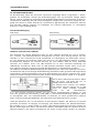
Congratulations!
With buying an Electro-Voice PRECISION SERIES power amplifier you have chosen
an appliance that employs the most advanced technology.
P-Series power amps combine outstanding audio performance, highest reliability and operational
stability. Each power amplifier employs an RCM-24 Remote Control module allowing centralized
configuration, control and monitoring of all relevant power amp parameters (like output current, output
voltage, load impedance, etc.).
The gapless protection circuitry concept not only prevents the power amp itself but also the connected
loudspeaker systems from being damaged. These extensive protections include Dynamic Audio
Limiters, DC/HF-Protections, Back-EMF-Protection, Inrush Current Limiter, Short Circuit Protection
and of course Thermal Overload Protection for the output transistors and mains transformers.
Three-speed high performance fans guarantee outstanding thermal stability at absolute low running
noise. The ventilation is directed front-to-rear allowing trouble-free operation even in smaller amp-racks.
Comprehensively dimensioned power supply units with low-leakage toroidal transformers provide
extensive headroom far above the stated nominal power.
Mechanical construction and workmanship also comply with the highest precision manufacturing
standards. The rigid sheet steel chassis resists even the most wearing tour operation.
The RCM-24 provides full-size
overview of the system’s entire status
and control over all relevant system
parameters at any time. The RCM-
24 module allows integration into a
Monitoring the connected loudspeaker systems is performed through measuring output currents
and –voltages of the two power amplifier channels. Each time the signal falls below or exceeds set
limit values is immediately indicated and logged, thus detecting and indicating short circuits and line
interruption during normal operation. The integrated impedance test function allows more precise
checking the connected loudspeaker systems. The integrated signal generator is employed together
with the current/voltage testing to measure the connected loudspeakers’ and cable’s impedance
plus over the entire frequency range. The resulting impedance graph is displayed on the PC-screen.
Comparing the measured impedance progression to a reference value is possible at all times, which
allows recognizing even the slightest loudspeaker defects or irregularities.
Remote Control Network consisting of up to 250 power amps. The Windows Software IRIS – Intelligent
Remote Control Network consisting of up to 250 power amps. The Windows Software IRIS – Intelligent
Remote & Integrated Supervision – allows controlling and monitoring an entire PA-system from a
single or several PCs. Any operational status like initial power-on status, temperature, modulation,
limiting, activation of protections, deviation in the load impedance, etc., are centrally registered and
displayed, which provides the opportunity to take specific measures prior to the occurrence of critical
operational states. Programming an automatic response for exceeding or falling below specific limits is
possible as well. All parameters, e.g. power-on/off, levels, muting, filters, etc. can be controlled in real-
time and saved in any power amp.
DESCRIPTION

5
Next to controlling and monitoring, the RCM-24 Remote Control module provides comprehensive
signal processing functions. It includes a total of 20 parametric filter–, X-over functions, delays, routing
and level control as well as compressors and limiters per channel. All parameters can be freely edited
and stored in the module’s 8 user presets. Independent from network control all DSP-settings (filter,
delay, level) are maintained in case of failure. Additionally, the control inputs of the power amps can be
used for network-independent switching to another preset (e.g. alarm settings with maximum energy
for voice and text announcements).
Therefore, P-Series amps with RCM-24 modules installed fulfil even the highest safety requirements.
When designing the RCM-24, uncompromising audio quality was the highest maxim. AD/DA-
conversion is performed at a resolution of 24-bit and 128-times oversampling with linear phase; the
internal word length is 48 bits. With this the RCM-24‘s dynamic range reaches 115 dB, which is an
absolute peak value for digital audio appliances.
All configuration, control and monitoring details of P-Series power amps are explained in the
documentation accompanying the PC Windows software IRIS.
UNPACKING & WARRANTY
Carefully open the packaging and take out the power amplifier. Next to the power amplifier itself, the
package also includes this owner’s manual, a mains cord, the warranty certificate, four stand-feet,
six screw-on connectors (1x 2-pole, 4x 3-pole, 1x 6-pole) plus a set of rack shelf mounting adapters.
Please inspect carefully whether all information in the warranty certificate has been filled in complete-
ly, since only a completely filled in warranty certificate entitles you to stake any warranty claims. The
appliance comes with a 36 months warranty, starting with the date when receiving the good from your
dealer. Therefore, keep the original invoice together with the warranty certificate at a safe place.
INSTALLATION NOTES
Generally, installing or mounting power amps should be carried out in a way that guarantees
continuously unopposed front-to-rear air circulation. When including an appliance in a closed cabinet
or rack shelf system make sure to provide sufficient ventilation. Leave a gap of at least 60mm x
330mm (up to the cabinet’s top ventilation louvers) for air circulation between the rear of the power
amplifier and the cabinet’s/rack’s rear wall. Make sure to leave at least 100mm of space above the
cabinet or rack shelf system. Since the temperature inside of the cabinet or rack shelf system can
easily rise up to 40°C during operation, bearing in mind the maximally allowable environmental
temperature during operation for all other appliances installed in the same rack shelf system is
mandatory.
(also refer to “MAINS OPERATION & RESULTING TEMPERATURE”)
The use of rails or optionally available rack
adapters – NRS 90235 (112733) – is mandatory
as well when installing the appliance in a rack
shelf system to prevent the front panel from
bending.
Caution:
For problem-free operation exceeding the maximally allowable environmental
temperature or +40°C is not permissible.
The power amplifier has to be protected against: dripping or splashing water, direct sunlight, high
temperatures or direct influence of heat sources, high humidity, extensive dust and vibrations.
Condensation on internal parts may occur after transporting the power amplifier from a cold into a
warmer environment. In that case operation is only permissible after the appliance has gained the
new temperature (after approximately one hour). If foreign objects or liquids have entered the power
amplifier’s enclosure make sure to instantly separate the appliance from the mains power and contact
an authorised DYNACORD service centre for inspection before continuing operation.
Do not use any sprays or solvents for cleaning the appliance, because they might severely damage the
surface of the enclosure or lead to dangerous fire hazard.
31.75
1
1/4
“
44.45
44.45
44.45
44.45
44.45
1
3/4
“
44.45
15
1/2
“
DESCRIPTION

6
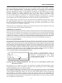
FRONT VIEW
This indicator lights when the power amplifier has been switched on. Causes for
the POWER-indicator not lighting are: the appliance is not connected to the mains
network, a defective primary fuse, or the power amplifier is set to stand-by operation
(STAND-BY LED lights).
This indicator light when the power ampli er is in stand-by mode, which can be
activated from the RCM-24 or via Easy Remote. In stand-by operation only the
internal auxiliary power supply unit is activated. The main power supply unit is
separated from the mains.
The PROTECT LED lights indicating that one of the internal protection circuits
against thermal overload, short-circuit, Back-EMF, HF-occurrence at the output, etc.,
has been activated. In that case, the output relays separate the power amps from
the load connected to prevent the connected loudspeaker systems and the power
amplifiers as well from being damaged. Whatever caused the fault – e.g. a short-
circuited speaker cable –
needs to be remedied. In case of thermal overload you
have to wait until the power ampli er automatically regains normal operation
.
The OUT LED lights as soon as an audio signal of approximately 30dB below full
modulation is present. The LED is dimmed when speaker cables are short-circuited
or a protection circuit has been activated
.
The 0dB LED lights when the power amplifier is driven at its maximum. Higher input
voltage does not result in higher peak output voltage.
This indicator lights as soon as the integrated dynamic limiter is activated and the
power amplifier is driven at the clipping limit or generally at its maximum capacity.
Short-term blinking is not a problem, since the internal limiter trims input levels of up
to +21dBu down to a S/N-ratio of approximately 1%. If, on the other hand, this LED
lights constantly, reducing the volume is recommended to prevent the loudspeaker
systems connected from being damaged by probable overload
.
Use the
POWER switch
located in the centre of the front panel to switch the appliance’s power
on. The soft-start function prevents current inrush peaks on the mains, which in addition prevents
the mains line protection switch from activating during power-on operation of the power amplifier.
The loudspeaker outputs are activated via relay switching with a delay of approximately 2 seconds
effectively attenuating eventual power-on noise. The PROTECT LED lights during the delay time and
the fans run at maximum speed. This is normal to confirm the immaculate operation of the protection
circuitry. Upon power-on, all power amps with RCM-24 Module installed regain the state of operation
prior to the last power-off.
For example: if a power amplifier had been switched off using the POWER-switch while being in Stand-
by mode, upon power-on it restarts in this exact mode.
This indicator light when the power ampli er is in stand-by mode, which can be
activated from the RCM-24 or via Easy Remote. In stand-by operation only the
internal auxiliary power supply unit is activated. The main power supply unit is

7
INPUT A / INPUT B
This indicator lights as soon as the integrated dynamic
limiter is activated and the power amplifier is driven at
the clipping limit or generally at its maximum
capacity. Short-term blinking is not a problem, since
the internal limiter trims input levels of up to +21dBu
down to a S/N-ratio of approximately 1%. If, on the
other hand, this LED lights constantly, reducing the volume is recommended to prevent the loudspeak-
er systems connected from being damaged by probable overload
.
PARALLEL CONNECTION
Connection can be established via the XLR-type input connectors INPUT A / INPUT B or the supplied
screw-on connectors which are connected in parallel. In addition, using the PARALLEL-connectors
provides the possibility for connecting the input signal through to feed additional power amplifiers,
without the need for extra splitter-cables
.
DSP OUT
The DSP output signal – i.e. the post-digital-signal-processing-unit audio signal – is present at the
DSP OUT. The DSP output signal is simultaneously fed to the power amplifier output stage and is
correspondingly amplified present at the power amp’s main outputs.
The DSP OUT can be utilized for feeding the digitally processed audio signal from the RCM-24 Re-
mote Control Module to additional power amplifiers (without DSP-module); e.g. for increasing the
overall output power. With a nominal level of +6dBu and a maximum level of +21dBu (8.7V) the output
signal is electronically balanced. Output impedance is 100
Ω
.
CONTROL PORT
The CONTROL PORT offers two freely programmable control inputs and
control outputs as well as the reference connections for ground potential and
+5V. Using the PC Windows software IRIS, the control inputs can be
configured and serve for instance for Power-On / Stand-by switching, preset
switching or parameter control.
The two control contacts IN1 / IN2 are internally set to +5V (open) via pull-up
resistors. Activating the control inputs is possible by closing the contacts to ground potential (pin 3) via
external switches, pushbuttons or relays.
The two control outputs OUT1 / OUT2 are carried out as Open Collector Outputs. In non-active state
(Off) they provide high ohmic resistance. In the active state (On) these outputs are connected to
ground. The outputs serve for signalling internal operational states. They can be used for the direct
triggering of LEDs, indication lights or relays. The +5V reference connector provides power supply for
externally connected appliances with amperage of maximally 100mA. The control outputs allow signal
indication of operational states (critical temperature, exceeding or decline of defined limit values, faults,
etc.) at central operator desks or to other systems (fire alarm system, general alert system) even with-
out PC. For further detail about configuring the control ports, please refer to the documentation accom-
panying the IRIS software.
REAR PANEL
The CONTROL PORT offers two freely programmable control inputs and
control outputs as well as the reference connections for ground potential and
+5V. Using the PC Windows software IRIS, the control inputs can be
configured and serve for instance for Power-On / Stand-by switching, preset
switching or parameter control.
The two control contacts IN1 / IN2 are internally set to +5V (open) via pull-up
other hand, this LED lights constantly, reducing the volume is recommended to prevent the loudspeak-

8
REAR VIEW
RS-232 INTERFACE
The RS-232 interface is for connecting media control systems as well as
building management systems providing control and monitoring of all
parameters. Communication is established via an easily to implement ASCII-
protocol allowing trouble-free integration of Remote Amplifiers in media and
touch panel control systems. For a programmer’s guide and complete protocol description, please refer
to the documentation accompanying the IRIS software
.
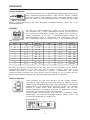
ADDRESS
The address selection switch allows setting the amplifier’s network address,
which, within a CAN-network, can range from 01 to 250 (FA hex). Caution:
Each address may exist only once within a network. Otherwise network
conflicts might occur. Address setting has to be performed in hexadecimal
code. The selection switch LOW represents the low-value digit while the
HIGH-switch represents the high-value digit
.
Adress-Table:
HIGH
LOW
Adress
HIGH
LOW
Adress
0
0
Stand-alone
8
0 ... F
128 ... 143
0
1 ... F
1 ... 15
9
0 ... F
144 ... 159
1
0 ... F
16 ... 31
A
0 ... F
160 ... 175
2
0 ... F
32 ... 47
B
0 ... F
176 ... 191
3
0 ... F
48 ... 63
C
0 ... F
192 ... 207
4
0 ... F
64 ... 79
D
0 ... F
208 ... 223
5
0 ... F
80 ... 95
E
0 ... F
224 ... 239
6
0 ... F
96 ... 111
F
0 ... A
240 ... 250
7
0 ... F
112 ... 127
F
B ... F
reserved
Address 0 (00 hex, factory-pre-set) ensures that the amplifier is separated from the remote
communication, so that it does not appear in the system set-up even though it might be connected
to the CAN-bus. When the amplifier is powered-on with its address set to “0”, all internal parameters
are set to “0” respectively to bypass and the routing is set to 2-in-2. In that case the amplifier behaves
absolutely linear, i.e. signal processing is deactivated
.
REMOTE CAN BUS
Each amplifier employs two RJ-45 sockets for Remote CAN-bus connection.
The sockets are parallel connected and serve as input as well as for
connecting through of the Remote network. Common RJ-45 patch
cables can be used for rack-shelf cabling. The CAN-bus needs to be
terminated at both ends using a 120ohms termination plug. Detailed
guidelines concerning cabling and bus length are provided in the chapter
“REMOTE CONTROL NETWORK”.
Both RJ-45 sockets additionally carry the balanced audio monitor signal. The
nominal output level is +6dBu (1.55V) while the maximum output level is +21dBu (8.7V).
Connector Pin-Assignment:
(View of Contacts)
touch panel control systems. For a programmer’s guide and complete protocol description, please refer

9
EASY REMOTE
Easy Remote provides a simple way to remotely power-on/off the power
amplifier. The Easy Remote function is only useful for appliances not
employing a RCM-24 Module. Controlling appliances with RCM-24 Module
installed per Easy Remote is practically pointless
.
EASY REMOTE IN
Leaving the pins of the EASY REMOTE IN socket open, i.e. when connecting +5V, the appliance
power is switched on. When connecting the EASY REMOTE IN, i.e. when feeding 0V from the control
output, the appliance enters standby mode
.
EASY REMOTE SLAVE
The EASY REMOTE SLAVE connector provides connection for additional appliances with Easy-
Remote function (e.g. for switching several devices within a rack-shelf ON/OFF).
The switching of the slave-units is delayed to prevent the mains fuses from blowing.
POWER AMPLIFIER OUTPUTS
4-pole binding-post terminals are provided for the power amplifier channels
„A“ and „B“.
When connecting loudspeaker systems, please mind the polarity
according to the here shown diagram.
Since the binding-post terminals might carry high voltages during
operation that might cause shock-hazard, closing the attached cover is
mandatory after establishing loudspeaker connections.
GROUND-LIFT SWITCH
The ground-lift switch allows eliminating noise loops. If the power amplifier is
operated together with other equipment in a 19“ rack-shelf, setting the switch
to its GROUNDED position is recommended. If the power amplifier is
operated together with appliances with differing ground potentials, setting
the switch to its UNGROUNDED position is recommended
.
MAINS INPUT
Under normal circumstances, the mains fuse only blows in case of fault.
Replacing the fuse is only permissible when using a new fuse of the same
type with identical amperage, voltage and blow characteristics. If the mains
fuse blows more often, please contact an authorized service centre.
When connecting loudspeaker systems, please mind the polarity
according to the here shown diagram.
operation that might cause shock-hazard, closing the attached cover is
REAR VIEW
The STATUS LED provides optical indication of CAN-bus traffic. When the
power amplifier’s address is set to “00” so that it is separated from the CAN-
bus, the STATUS LED blinks every 3 seconds. When the power amplifier’s
address is set between “01” and “250” and no CAN-bus activity has taken
place yet, the LED blinks every second. As soon as CAN-bus communication is recognized, the LED is
activated for at least 100ms whenever the power amplifier actively sends data on the CAN-bus.
The STATUS LED may also be activated from the PC. In this case, the LED of the according power
amplifier blinks fast and steady while all other status-LEDs within the system stay dimmed
.

10
CABLING
NF-VERBINDUNGSKABEL
Choosing balanced cables (two conductors for the audio signal plus separate shielding mesh) with
XLR-type connectors is recommended for LF-signal connection. Although connecting unbalanced
cables to the power amplifier inputs is possible as well, using balanced cabling is always preferable. A
great number of today’s audio appliances employ balanced outputs. With balanced cabling, the shield
connects all metal enclosure parts and thus efficiently eliminates the introduction of noise and hum
.
XLR-type connector pin-assignment
XLR (male)
XLR (female)
REMOTE CONTROL NETWORK
The network of the remote power amps is based on the CAN-bus standard, which for years is
especially popular in automotive, industrial and security applications. The CAN-bus is a balanced
serial interface for command and data transmission. Controlling the power amplifiers is performed
from a PC with IRIS – Intelligent Remote & Integrated Supervision – software installed. The UCC1
USB-CAN Converter serves as interface between the PC and the CAN-bus. Connecting up to 100
power amplifiers per CAN-Bus with a maximum total cable length of 1,000 meters is possible. An
additional CAN-bus is needed for controlling more than 100 power amps while the IRIS software allows
administering a total of 250 power amps.
The network topology used by the CAN-bus is based on the so-called “bus or line topology”, i.e. all
participants are connected via a single two-wire cable (Twisted-Pair cable, shielded or unshielded)
with the cabling running from one participant on the bus to the next, allowing unlimited communication
among all appliances. In general, it does not matter whether a participant on the bus is a power
amplifier or an UCC1 USB-CAN converter,
so that both – UCC1 and the PC as well
– can be inserted at any position.
Incorporating several UCC1 and PCs
on a single CAN-bus is also possible.
A total of up to 100 appliances can be
operated on a single CAN-bus. Since the
CAN-interfaces of all appliances are
galvanically separated from the rest of the circuitry, network cabling also carries a common ground
conductor (CAN_GND) ensuring that all CAN-interfaces in the network are connected to a common
ground potential. The UCC1 provides the possibility for switching the CAN-ground to circuit-ground.
Each participant on the bus system has two RJ-45 connectors for the Remote CAN-bus. These sockets
are connected in parallel to serve as input and output (for connecting through) for the data transfer
within the remote-network. The CAN-bus has to be terminated at both ends using 120
Ω
terminator
plugs, two of which – CAN-TERM 120
Ω
– are supplied with the UCC1. Connect one of these to the
RJ-45 socket of the first and the other to the socket of the last appliance on the CAN-bus
.

11
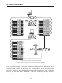
NETWORK EXAMPLES
The following diagrams show examples of the data-bus wiring for different order of size:
System with 5 amps and one UCC1 / PC at the beginning of the bus
Terminators at the UCC1 ( rst unit on the bus) and at amp 5 (last unit on the bus)
System with 2 amp-racks and an UCC1 / PC in the middle
Terminators at amp 6 ( rst unit on the bus) and amp 12 (last unit on the bus)

12
NETWORK EXAMPLES
System with several amp-racks and several UCC1 / PCs
UCC1s anywhere on the CAN-bus
Terminators at amp 10 ( rst unit on the bus) and amp 16 (last unit on the bus)
Next to the CAN-bus signal, network cabling also carries the balanced monitor audio signal for
monitoring the power amp inputs and outputs. This monitor-bus allows software-controlled monitoring
of the input and output signals of all power amps that are included in the remote network, without the
need for additional wiring. The monitor signal is present at the UCC1’s XLR-type MONITOR Output
connector for further distribution to (e.g.) a mixing console to be monitored via headphones or an
active monitor speaker connected
.

13
The CAN-bus allows using different data rates, with the data
rate being indirectly proportional to the bus length. Small
networks allow baud rates up to 500kbit/s.
For sizable dimensioned networks reducing the baud rate
(minimum 10kbit/s) is necessary.
The integration of repeaters is generally recommended
when the bus-length exceeds 1,000m.
Baud Rate
Bus Lenght
500 kbit/s
100 m
250 kbit/s
250 m
125 kbit/s
500 m
62.5 kbit/s
1000 m
20 kbit/s
2500 m
10 kbit/s
5000 m
CAN-Bus
CABLE SPECIFICATIONS
According to the ISO 11898-2 standard, CAN-bus data transfer cabling has to be carried out using
Twisted-Pair cables with or without shielding providing a characteristic impedance of 120
Ω
. Both ends
of a CAN-bus need to be terminated with 120
Ω
termination-plugs.
The maximum bus-length depends on the actual data transfer rate, the kind of data transfer cable
being used, as well as the total number of participants on the bus. The following table shows the most
essential coherencies for CAN-networks consisting of up 64 participants
:
Bus Length
Cable for data Transmission
Termination
max.
Data Transfer Rate
Resistance per
Unit Length
Cable Diameter
0 ... 40 m
< 70 m
Ω
/m
0.25 ... 0.34 mm²
AWG23, AWG22
124
Ω
1000 kbit/s bei 40 m
40 ... 300 m
< 60 m
Ω
/m
0.34 ... 0.6 mm²
AWG22, AWG20
127
Ω
500 kbit/s bei 100 m
300 ... 600 m
< 40 m
Ω
/m
0.5 ... 0.6 mm²
AWG20
150
Ω
... 300
Ω
*
100 kbit/s bei 500 m
600 ... 1000 m
< 26 m
Ω
/m
0.75 ... 0.8 mm²
AWG18
150
Ω
... 300
Ω
*
62.5 kbit/s bei 1000 m
*
With longer cables and many participants on the CAN-bus, termination resistors with higher impedance than the
specified 120
Ω
are recommended to reduce the ohmic load of the interface drivers and therefore the voltage drop
between the two cable ends
.
The following table is meant for first assessment of necessary cable diameters for different bus lengths
and bus-participant numbers
:
Bus Length
Number of Appliance on the CAN-Bus
32
64
100
100 m
0.25 mm² bzw. AWG24
0.34 mm² bzw. AWG22
0.34 mm² bzw. AWG22
250 m
0.34 mm² bzw. AWG22
0.5 mm² bzw. AWG20
0.5 mm² bzw. AWG20
500 m
0.75 mm² bzw. AWG18
0.75 mm² bzw. AWG18
1.0 mm² bzw. AWG17
Additionally, the length of branch lines – for participants that are not directly connected to the CAN-bus
– is also of importance. For data transfer rates of up to 125kbit/s, the maximum length of a single stub
cable should not exceed 2m. For higher bit rates a maximum length of only 0.3m is still permissible.
The entire length of all branch lines should not exceed 30 m.
General Note:
As long as only short distances (up to 10m) are concerned, common RJ-45 patch cables with
100
Ω
characteristic impedance (AWG 24 / AWG 26) can be used for the cabling inside of a
rack-shelf system. The previously outlined guidelines for network cabling are mandatory as far
as the rack-shelve interconnection or xed installations are involved
.
CAN-BUS

14
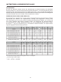
MAINS OPERATION & RESULTING TEMPERATURE
P1200RL
U
Mains
[V]
I
Mains
[A]
P
Mains
[W]
P
out
[W]
P
d
[W]
BTU/hr
(3)
Idling
230V
0.55
85
-
85
290
Max. Output @ 8
Ω
(1)
230V
6.40
1185
2 x 380
425
1450
Max. Output @ 4
Ω
(1)
230V
10.5
2030
2 x 600
830
2832
max. Output @ 4
Ω
(1)
230V
6.60
1230
2 x 200
830
2832
max. Output @ 4
Ω
(2)
230V
3.80
675
2 x 75
525
1791
Normal Operation (-10dB) @ 4
Ω
(1)
230V
3.78
670
2 x 50
570
1945
Nominal operation (0dB)
@ 4
Ω
(1)
230V
9.69
1870
2 x 500
870
2969
Alarm Operation (-3dB)
@ 4
Ω
(1)
230V
7.27
1370
2 x 250
870
2969
P900RL
U
Mains
[V]
I
Mains
[A]
P
Mains
[W]
P
out
[W]
P
d
[W]
BTU/hr
(3)
Idling
230V
0.45
70
-
70
239
Max. Output @ 8
Ω
(1)
230V
4.97
920
2 x 280
360
1228
Max. Output @ 4
Ω
(1)
230V
8.16
1580
2 x 450
680
2320
max. Output @ 4
Ω
(1)
230V
5.13
960
2 x 150
660
2252
max. Output @ 4
Ω
(2)
230V
2.90
520
2 x 56.3
407.5
1390
Normal Operation (-10dB) @ 4
Ω
(1)
230V
2.84
505
2 x 35
435
1484
Nenn Operation (0dB)
@ 4
Ω
(1)
230V
7.32
1410
2 x 350
710
2423
Alarm Operation (-3dB)
@ 4
Ω
(1)
230V
5.48
1030
2 x 175
680
2320
For approximation; when operating the appliance at 120V mains the stated current values need to be doubled.
(1) modulated with sine signal
(2) modulated with VDE-noise
(3) 1BTU = 1055.06J = 1055.06Ws
MAINS OPERATION
The following tables allow determining power supply and cabling requirements. The values of
the column „1/8 max. Output @ 4
Ω
” are relevant for “normal” operation. These values are based
on operating the power amplifier with VDE-noise at 1/8 of the maximum output power, which
approximately equates the load of the power amplifier being operated with a music signal at maximum
volume possible, without noticeable clipping
.
RESULTING TEMPERATURE INSIDE THE POWER AMPLIFIER
The power drawn from the mains network is converted into acoustic output power to feed the
connected loudspeaker systems & heat. The difference between drawn power and dispensed power
is called leakage power or dissipation (Pd). The amount of heat resulting from power dissipation might
remain inside of a rack-shelf and needs to be diverted using appropriate measures. The following table
provides auxiliary means for calculating the temperatures inside of a rack-shelf system/cabinet and the
ventilation efforts necessary.
The column “Pd” lists the leakage power in relation to different operational states. The column “BTU/hr”
lists the dispensed heat amount per hour
.
Page is loading ...

16
INHALT
WICHTIGE SICHERHEITSHINWEISE
.......................
17
WICHTIGE SERVICEHINWEISE
.......................
17
BESCHREIBUNG
.......................
18
AUSPACKEN & GARANTIE
.......................
19
INSTALLATIONSHINWEISE
.......................
19
FRONTSEITE
.......................
20
RÜCKSEITE
.......................
21
INPUT A / INPUT B
.......................
21
PARALLEL
.......................
21
DSP OUT
.......................
21
CONTROL PORT
.......................
21
RS-232 INTERFACE
.......................
22
ADDRESS
.......................
22
REMOTE CAN-BUS
.......................
22
EASY REMOTE
.......................
23
ENDSTUFENAUSGÄNGE
.......................
23
GROUND-LIFT SCHALTER
.......................
23
NETZEINGANG
.......................
23
VERKABELUNG
.......................
24
NF-VERBINDUNGSKABEL
.......................
24
REMOTE CONTROL NETZWERK
.......................
24
NETZWERK-BEISPIELE
.......................
25
CAN-BUS
.......................
27
NETZBETRIEB & WÄRMEENTWICKLUNG
.......................
28
SPECIFICATIONS / TECHNISCHE DATEN
.......................
29
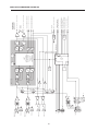
BLOCK DIAGRAM AMPLIFIER
.......................
31
BLOCK DIAGRAM RCM-24
.......................
32
DIMENSIONS / ABMESSUNGEN
.......................
33
Page is loading ...
Page is loading ...
Page is loading ...
Page is loading ...
Page is loading ...
Page is loading ...
Page is loading ...
Page is loading ...
Page is loading ...
Page is loading ...
Page is loading ...
Page is loading ...

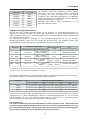
29
SPECIFICATIONS / TECHNISCHE DATEN
P900RL
P1200RL
Load Impedance
8
Ω
4
Ω
2
Ω
8
Ω
4
Ω
2
Ω
Maximum Midband Output Power
THD = 1%, 1kHz
2x
280W
2x
450W
2x
650W
2x
380W
2x
600W
2x
850W
Rated Output Power
THD < 0.2%, 20Hz ... 20kHz
2x
175W
2x
350W
-
2x
250W
2x
500W
-
Max. Single Channel Output Power
Dynamic-Headroom, IHF-A
340W
640W
720W
460W
880W
950W
Maximum RMS Voltage Swing
THD = 1%, 1kHz
56V
64V
Power Consumption
at 1/8 maximum output power @ 4
Ω
690W
870W
THD at rated output power,
MBW = 80kHz, 1kHz
< 0.05%
IMD-SMPTE
60Hz, 7kHz
< 0.08%
DIM30
3.15kHz, 15kHz
< 0.03%
Crosstalk Attenuation
ref. 1kHz, at rated output power
> 80dB
Frequency Response
-1dB, ref. 1kHz
15Hz ... 22.5kHz
Damping Factor
at 100Hz / 1kHz, 8
Ω
> 300 / > 200
Signal to Noise Ratio, Ampli er
A-weighted
106dB
Signal to Noise Ratio, System
A-weighted
100dB
Input Sensitivity
at rated output power @ 4
Ω
, 1kHz
+6dBu (1.55V)
Max. Input Voltage
+21dBu (8.7V)
Input Impedance
20Hz ... 20kHz, balanced
20k
Ω
CMR
1kHz
80dB
Output Voltage
DSP OUT / Monitor
rated: +6dBu (1.55V)
max: +21dBu (8.7V)
Output Impedance
DSP OUT / Monitor
< 100
Ω
Minimum Output Load
DSP OUT / Monitor
600
Ω
Digital Signal Processing
AD & DA Conversion
24 Bit, Sigma-Delta, 128 x Oversampling, Linear Phase
Sample Rate
48kHz
Internal Wordlength
48 bit
Dynamic Range
115dB (typical)
Functions
Volume Control, Routing,
X-Over
(6, 12, 18, 24 dB/Oct Slope, Butterworth, Bessel, Linkwitz-Riley)
,
Filter
(Parametric EQ, Lo / Hi Shelving EQ, LPN, Lo / Hi Pass, Allpass)
,
Compressor / Limiter,
Delay
- System (ampli er) at rated conditions, both channels driven, 8
Ω
loads, unless otherwise speci ed.
- Depending on the ambient temperature, the unit might not operate continuously at 2
Ω
load.

30
Interfaces
CAN-Bus, 10 ... 500 kbit/s, RJ-45 (PC Control)
RS-232, 19.2 kbit/s, 9-pol. SUB-D (Multi Media Control)
Control Port / GPIO
6-pol. Phoenix
2 Control Inputs
Inactive / OFF +5.0V (> 2.4V) or open (internal pull-up)
Active / ON
0V (< 0.8V)
2 Control Outputs
Inactive / OFF High (Open Collector)
Active / ON
Low (< 0.5V / I = 0.7A)
Input Voltage
+32.0V max.
Switching Current 1.0A max.
Reference Outputs +5.0V / 100mA and GND
Power Requirements
240V, 230V, 120V, 100V / 50Hz ... 60Hz,factory con gured
Protection
Audio limiters, High temperature, DC, HF, Back-EMF,
Peak current limiters, Inrush current limiters, Turn-on delay
Cooling
Front-to-rear, 3-stage-fans
Dimensions
(W x H x D), mm
483 x 132.5 x 426
Weight
16kg
17kg
Optional Input Transformer
Optional Output Transformer
(Monitor)
Rear-rackmount 15,5“
Rear-rackmount 18“
NRS 90208 (121 641)
NRS 90227 (112 679)
NRS 90235 (112 733)
NRS 90223 (112 701)
SPECIFICATIONS / TECHNISCHE DATEN
Page is loading ...

32
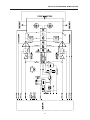
BLOCK DIAGRAM RCM-24
A
D
A
D
D
A
D
A
A
D
A
D
24 BIT
DSP
SRAM
512k x
8
GAINRANGING
24 BIT ADC
GAINRANGING
24 BIT ADC
LP
F
LP
F
DUAL
24 BIT DAC
INPUT
PARALLEL
-15V
+15V
AMPLIFIER
INTERFACE
CONTROL / SUPERVISION:
INPUT / OUTPUT LEVEL METER
PILOT SIGNAL GENERATOR
PILOT SIGNAL DETECTION
IMPEDANCE MEASUREMEN
T
AMP INPUT CH. A (SIGNALA / SENSINA)
AMP INPUT CH. B (SIGNALB / SENSINB)
ANALOG
POWER
SUPPLY
CLOCK
12.288 MHz
POWER
SUPPLY
CPU +
FLASH
RAM
A
D
CAN
UART
RESET
WATCHDOG
EEPRO
M
AMP TEMPERATURE (TEMP)
OUTPUT CURRENT CH.A (OUTCURA+/-)
OUTPUT CURRENT CH.B (OUTCURB+/-)
AMP OUTPUT RELAYS (TIMER)
OUTPUT VOLTAGE CH.A (OUTVOLA+/-)
STANDBY POWER SOURCE
+5V
+3.3V
DC
DC
RJ-45
MONITOR BUS
CAN / RS-485
+5V
CAN / RS-485
TRANSCEIVER
MONITOR
OUT B
MONITOR
IN A
MONITOR
IN B
MONITOR
OUT A
SLAVE OUT A
SLAVE OUT B
CLOCK
SPI
D
A
D
A
DUAL ADC
DUAL AD
C
I/O
DEVICE
ADDRESS
STATUS
SIGNAL PROCESSING:
FILTERS, X-OVER
DELAY
COMPRESSOR, LIMITER
ROUTING, LEVEL, POLARITY
I/O
MAINS POWER ON/OFF (POWER_ON)
AMP TYPE CODE (AMP_ID1-8)
LIMITER CH. A (LIMOUTA)
LIMITER CH. B (LIMOUTB)
GPIO
CONTROL
PORT
8
OUTPUT VOLTAGE CH.B (OUTVOLB+/-)
INPUT LEVEL CH. B
INPUT LEVEL CH.
A
+5V
GND
GROUND
FAULT
DETECTION
AMP PROTECT (PROTECT)
CHASSIS
8
STANDBY/ON SIGNAL (STANDBY)
4
CHANNEL A
INPUT
CHANNEL B
PARALLEL
GROUND FAULT CH. A (GNDFLTA)
GROUND FAULT CH. B (GNDFLTB)
VU INPUT A
VU INPUT B
DSP DIGITALBOARD
80477
NRS 90227
NRS 90208
NRS 90208
Page is loading ...
Page is loading ...
Page is loading ...

36
USA
Telex Communications Inc., 12000 Portland Ave. South, Burnsville, MN 55337, Phone: +1 952-884-4051, FAX: +1 952-884-0043
Germany
EVI AUDIO, Hirschberger Ring 45, D 94315, Straubing, Germany Phone: 49 9421-706 0, FAX: 49 9421-706 265
Subject to change without prior notice.
Printed in Germany
10/08/2002 / 361 609
www.electro-voice.de
-
 1
1
-
 2
2
-
 3
3
-
 4
4
-
 5
5
-
 6
6
-
 7
7
-
 8
8
-
 9
9
-
 10
10
-
 11
11
-
 12
12
-
 13
13
-
 14
14
-
 15
15
-
 16
16
-
 17
17
-
 18
18
-
 19
19
-
 20
20
-
 21
21
-
 22
22
-
 23
23
-
 24
24
-
 25
25
-
 26
26
-
 27
27
-
 28
28
-
 29
29
-
 30
30
-
 31
31
-
 32
32
-
 33
33
-
 34
34
-
 35
35
-
 36
36


Electro-Voice P900RL P1200RL User manual
- Category
- Audio amplifiers
- Type
- User manual
- This manual is also suitable for
Ask a question and I''ll find the answer in the document
Finding information in a document is now easier with AI
in other languages
Related papers
-
Electro-Voice P3000RL User manual
-
-
-
Electro-Voice CP-Series Power Amps CP1800 Owner's manual
-
Electro-Voice UCC 1 Owner's manual
-
-
-
-
-
Other documents
-
Omnitronic PAA Series User manual
-
IMG Stage Line STA-1503CLUB B User manual
-
DYNACORD DSA 8405 Owner's manual
-
-
-
-
Dali AMP-2500 DSP User guide
-
-
-