Page is loading ...

Operator's Manual
®
11/4- 21/2" Length
COIL UTILITY NAILER
Model No.
351.182140
CAUTION: Read and follow
all Safety Rules and Operating
Instructions before First Use
of this Product. Keep this
manual with tool.
Sears, Roebuck and Co., Hoffman Estates, IL 60179 U.S.A.
www.sears.com/craftsman
21662.00 Draft (01/12/04)
• Safety
• Operation
• Maintenance
• Parts List
• Espa5ol

Warranty ......................................... 2
Safety Rules ...................................... 2
Operation ...................................... 3-6
Maintenance ..................................... 6
Troubleshooting ................................... 7
Parts Illustration and List .......................... 8-9
EspaSol ...................................... 10-15
FULL ONE YEAR WARRANTY
If this product fails due to a defect in material or workmanship
within one year from the date of purchase, Sears will at its
option repair or replace it free of charge. Contact your nearest
Sears Service Center (1-800-4-MY-HOME) to arrange for
product repair, or return this product to place of purchase for
replacement.
If this product is used for commercial or rental purposes, this
warranty will apply for 90 days from the date of purchase.
This warranty applies only while this product is used in the
United States.
This warranty gives you specific legal rights, and you may also
have other rights which vary from state to state.
Sears, Roebuck and Co., Dept. 817WA, Hoffman Estates,
IL 60179
* Read and follow all safety rules and operating instructions
in this manual and on warning label of tool before using
this tool. Keep this manual with the tool.
* Keep work area clean and properly lighted.
* Keep children, bystanders and visitors at a safe distance
from work area while operating this tool.
* Air tool operators and all others in work area should
always wear safety goggles complying with United States
ANSI Z87.1 to prevent eye injury from fasteners and flying
debris when loading, operating and unloading this tool.
Everyday eyeglasses have only impact resistant lenses.
These are NOT safety glasses. ANSI Z87.1 safety glasses
have permanently attached rigid, hard plastic side shields
and will have "Z87.1" printed or stamped on them.
* Always wear ear protection. The work area may include
exposure to excessive noise levels which will require nec-
essary ear protection. Some environments will require
head protection; use head protection conforming to ANSI
Z89.1.
* Do not alter or modify this tool in any way. Do not use this
tool for any application other than for which it was
designed.
* Do not use oxygen, carbon dioxide, high-pressure com-
pressed gas or bottled gases as the power source for this
tool. The tool will explode and serious personal injury
could result.
* Never connect the tool to air pressure which could poten-
tially exceed 200 psi. Use only clean, dry, regulated air
within rated range as marked on tool.
* The tool must have a male, free-flow hose coupling so that
all air pressure is removed from the tool when the coupling
joint is disconnected. Failure to use proper coupling could
cause accidental discharge, possibly causing injury.
* Only use air hose that is rated for a maximum working
pressure of 150 psi or 150% of the maximum system pres-
sure, whichever is greater.
* Do not use a hose swivel connector with this tool.
* Do not pull trigger or depress contact trip while connecting
to the air supply, as the tool may cycle, possibly causing
injury.
* When loading tool: Do not pull trigger or depress contact
trip; Do not point the tool at yourself or others; Do not
place hand or any part of body in the fastener discharge
area of the tool as accidental actuation may occur and
cause injury.
* Disconnect tool from air supply before loading or unload-
ing, performing tool maintenance, clearing a jammed fas-
tener, leaving work area, moving tool to another location or
handing the tool to another person.
* Use Sears recommended fasteners only.
* Do not load the tool until you are ready to use it.
* Always assume that the tool contains fasteners. Keep the
tool pointed away from yourself and others at all times.
Never engage in horseplay. Never pull the trigger unless
the contact trip is in contact with the workpiece. Keep oth-
ers at a safe distance from the tool while the tool is in
operation.
* Always remove finger from trigger when not driving fasten-
ers. Never carry the tool with finger on or under the trigger
as accidental actuation may occur and cause injury.
* Always keep hands and body away from the fastener dis-
charge area when air supply is connected to the tool. Grip
tool firmly to maintain control while allowing tool to recoil
away from work surface as fastener is driven. If contact trip
is allowed to recontact work surface before trigger is
released, an unwanted fastener may be driven.
* Check operation of the contact trip frequently. Never use
the tool if the contact trip, trigger or springs have become
inoperable, missing or damaged. Do not alter or remove
contact trip, trigger or springs. Never use a tool that is leak-
ing air, has missing or damaged parts, or requires repair.
* Do not drive fasteners on top of other fasteners or with the
tool at too steep an angle. The fasteners can ricochet and
cause injury. Do not drive fasteners close to the edge of
the workpiece. The workpiece is likely to split, allowing the
fastener to fly free and cause injury. Do not attempt to
drive fasteners into hard or brittle materials such as con-
crete, steel or tile.
* Do not overreach. Always place yourself in a firmly bal-
anced position when using or handling the tool. Do not
attach the hose or tool to your body.
* Do not operate tool without fasteners or damage to tool
may result.
* Do not use tool without safety warning label. If label is
missing, damaged or unreadable, contact SEARS to
obtain a new label.
* Only qualified repair personnel must perform tool service.
* When servicing a tool, use only identical repair parts.
* Store tool out of reach of children and other untrained
persons.
© Sears, Roebuck and Co. 2

DESCRIPTION
The Craftsman Coil Utility Nailer drives full head nails from
1_/4"to 2W' long. Magazine will hold a coil of 400 wire
collated nails. Safety feature disables tool unless contact trip
is pressed against workpiece. Sequential trigger switch allows
selection of rapid-fire or single-fire mode. Contact trip can be
adjusted for setting nail depth. Plastic protector on the end of
contact trip prevents marring of workpiece. Air deflector can
be adjusted to any direction. Die cast aluminum body with
textured rubber grip minimizes operator fatigue and makes
nailer lightweight and durable. The coil utility nailer is excellent
for siding, sheathing, exterior trim, subflooring, decking and
fencing.
SPECIFICATIONS
Capacity ..................... 400 wire collated coil nails
Nail size ....................... 0.082 to .110" diameter
Nail lengths ............................... 1_ to 2_/2''
Operating pressure ........................ 65-110 PSI
Air inlet ................................... W' N.P.T.
Length ....................................... 103/4''
Height ....................................... 11%"
Width .......................................... 5"
Weight ..................................... 4.2 Ibs.
NAILS
18081 (Box of 8000) ........... Galvanized nails, 13/4'' long
18082 (Box of 6000) ............ Galvanized nails, 2" long
AIR SUPPLY LINE
Refer to Figure 1.
DANGER: De not use oxygen, carbon dioxide, high-pressure
compressed gas or bottled gases as the power source for this
tool. The tool will explode and serious personal injury could
result.
• The air tool operates on compressed air at pressures from
65 to 110 PSI.
• Never connect the tool to air pressure which could poten-
tially exceed 200 PSI. Use only clean, dry, regulated air
within rated range as marked on tool.
Air Delivery Required: 1.87 SCFM @ 90 PSI
(30 shots per minute).
WARNING: Keep hands and body away from discharge area
of tool when connecting air supply. Always disconnect tool
from air supply when servicing or adjusting tool and when tool
is not in use.
• Air operated tools require clean, dry, lubricated com-
pressed air to ensure top performance, low maintenance
and long life.
• Dirt and abrasive materials present in all air lines will dam-
age tool O-rings, valves and cylinders.
• Moisture will reduce tool performance and life if not
removed from compressed air.
• A filter-regulator-lubricator system is required and should be
located as close to tool as possible. A distance of less than
15 feet is recommended.
• Keep air filter clean. A dirty filter will reduce the air pressure
to the tool causing a reduction in power and efficiency.
• The air supply system must be able to provide air pressure
of 65 to 110 pounds per square inch at tool.
° All hoses and pipes in the air supply system must be clean
and free of moisture and foreign particles. Hoses must be
rated for a maximum working pressure of 150 PSI or 150%
of maximum system pressure, whichever is greater.
° Do not mount swivel connector in air supply line.
° The air pressure should be properly regulated.
° Different workpiece materials and different fastener lengths
will require different operating pressure.
° Be sure all connections in air supply system are sealed to
prevent air loss.
° Never connect a female quick-disconnect coupling to the
tool side of air line connection. A male, free-flow coupling
should be connected to the tool side of air line connection
(see Figure 1).
WARNING: The female coupling provides a seal preventing
loss of compressed air from compressor tank when discon-
nected from male coupling. If connected to tool side of air
supply, the female coupling could seal a compressed air
charge in the tool which could discharge if the tool trigger is
actuated.
I
Male Connector
Female Connector
Figure 1 - Air Supply Line
LOADING
Refer to Figures 2 through 6, (pages 3 and 4).
WARNING: Disconnect tool from air supply. Do not load tool
until you are ready to use it. Do not pull trigger or depress
contact trip while loading tool. Always load with nose of tool
pointing away from you and others. Always wear safety gog-
gles that comply with United States ANSI Z87.1.
NOTE: For best results, use Sears fasteners only.
• Push the door latch down and swing the door open; then
swing the magazine cover open (see Figure 2).
Figure 2 - Opening the magazine

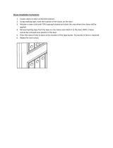
° The nail holder must be set to the length of the nails being
used. Twist the spindle of the nail holder and position nail
holder up or down so that the edge of the nail holder is
aligned with the correct size indicator on the inside of the
magazine. Twist spindle to lock nail holder in place (see
Figure 3).
CAUTION: Failure to adjust nail holder height may result in
damage to advance mechanism.
\
Nail Holder
Figure 3 - Adjust Nail Holder for Length of Nail
° Remove rubber band or tape holding nail coil. Place coil
over the spindle of nail holder in magazine (see Figure 4).
Figure 4 - Load Coil into the Magazine
Unwrap coil so that second nail can be placed between
sides of feed jaw. The ram (Fig. 11, No. 20) may need to be
pushed up to fit in the first nail. Make sure that the nail
heads are positioned in the slot at the top of the nail feed
rack (see Figure 5).
Nail Heads Must be
Positioned in This Slot
....,Second Nail Must Be
Positioned in Feed Jaw
Figure 5 - Load Nails into Feed Jaw
° Carefully close the magazine cover first. Then close the
door and secure in position with the latch. Make sure the
tab in the door holds the magazine cover in place
(see Figure 6).
Figure 6 - Close the Magazine Cover and Door
NAILING OPERATION
Refer to Figures 7 through 10 (page 5).
WARNING: Read and follow all safety rules and operating
instructions in this manual and on warning label of tool before
using this tool. Keep this manual with the tool.
WARNING: Do not use this tool without safety warning
label. If label is missing, damaged or unreadable, contact
Sears to obtain a new label.
WARNING: Never operate tool unless contact trip is in con-
tact with workpiece. Do not operate tool without fasteners or
damage to tool may result. Never fire fasteners into the air
because fasteners may injure operator or others and damage
to tool may result.
° Perform "Safety Mechanism Check" as described in the
Maintenance section (see page 6) prior to first use of tool
and on a daily basis thereafter.
4

• The tool is equipped with a rotating switch that can be set
to rapid-fire or single-fire mode (see Figure 7). When the
switch is set to single-fire mode, the tool will not drive a
second fastener until the trigger is fully released and
pulled again.
• When the switch is rotated to rapid-fire mode, the tool can
drive fasteners continuously. A fastener will be fired each
time the contact trip is pressed against the workpiece, as
long as the trigger is maintained in the pulled position.
Figure 7 - Push and Rotate Switch to Select
Operation Mode
SINGLE-FIRE OPERATION:
• The air tool is equipped with a contact trip safety mecha-
nism that disables tool unless contact trip is pushed
against work. To drive a fastener hold body firmly and
press contact trip on workpiece where fastener is to be
applied. Pull trigger to drive fastener into workpiece. To fire
a second fastener lift the tool from the workpiece, release
the trigger and then repeat the above sequence.
RAPID-FIRE OPERATION:
• The tool can also be operated by holding trigger
depressed and pushing contact trip against workpiece. A
fastener will be driven each time the contact trip is pushed
against the workpiece. This operating procedure provides
rapid-fire fastener driving. Never operate tool unless con-
tact trip is in contact with workpiece.
OPERATING PRESSURE
• Use only enough air pressure to perform the operation. Air
pressure in excess of that which is required will make the
operation inefficient and may cause premature wear or
damage to the tool.
• Determine minimum air pressure required by driving some
test fasteners into the workpiece. Set air pressure so that
test fasteners are driven down flush with the work surface.
Fasteners driven too deep may damage workpiece.
WARNING: All air power fastening tools recoil when operat-
ed. This recoil is caused by rapid driving of the fastener. Tool
may bounce from recoil causing a second unwanted fastener
to be driven. Reduce tool bounce by holding tool firmly in
hand and pressing tool gently against workpiece. Let the tool
do the work. This will allow recoil of tool to bounce tool away
from workpiece preventing the driving of second fastener.
CONTACT TRIP ADJUSTMENT
The contact trip may be adjusted up or down to vary the
driven depth of the fastener. To adjust, rotate depth control
knob (see Figure 8) to raise or lower contract trip to desired
setting.
Control
Knob
Figure 8 - Setting Depth Control
CONTACT TRIP PAD STORAGE
Pad can be removed and stored on the storage sleeve locat-
ed on the magazine (see Figure 9).
Figure 9 - Storing Contact Trip Pad
EXHAUST DEFLECTOR
° Exhaust deflector can be positioned to point in any direc-
tion (full 360° movement). Reposition deflector by grasping
firmly and rotating to the desired position (see Figure 10).
Exhaust
Deflector.
Figure 10- Exhaust Deflector Adjustment
5

COLD WEATHER OPERATION
CAUTION: Do not store in cold environment. Frost or ice
could form inside tool affecting operation and damaging tool.
Use a cold temperature lubricant, such as ethylene glycol,
when operating tool in freezing temperatures.
Refer to Figure 11.
LUBRICATION
Lubricate tool daily with quality air tool oil. If no air line lubri-
cator is used, place five or six drops of oil into air inlet cap
(Figure 11, Key No. 27) of tool everyday.
MAGAZINE AND PISTON-RAM
• Keep magazine and nose of tool clean and free of any dirt,
lint or abrasive particles.
The tip of the ram (Figure 11, Key No. 20) can become
dented or rounded over time.
• Square off the tip of the ram with a clean, fine hand file to
extend the life of the ram and tool. Fastener firing will be
more consistent if the ram tip is kept clean and square.
SAFETY MECHANISM CHECK
Inspect contact trip safety mechanism daily for proper opera-
tion. Do not operate tool if mechanism is not operating
properly.
With the red push-button switch in the rapid-fire mode, per-
form the following procedures to test safety mechanism:
• Leave trigger untouched while pushing contact trip into
workpiece. Tool must not fire.
• Pull trigger while contact trip is clear of work and pointed
away from operator and others. Tool must not fire.
• Depress and hold trigger. Push contact trip against work
where fastener is needed. The tool should drive only one
fastener each time the contact trip is pushed against
workpiece.
If contact trip mechanism does not operate properly,
repair tool immediately through Sears Service Center.
Replace any damaged or missing parts. Use the parts list to
order parts.
REBUILD KITS
Rebuild kits are available as spare parts, (see page 9). Tools
should be rebuilt if tool fails to operate properly after extended
use. See troubleshooting to determine required replacement
parts.
Disconnect tool from air supply before attempting repair
or adjustment.
NOTE: When replacing O-rings or cylinder, lubricate with
grease before assembly.
6

SYMPTOM POSSIBLE CAUSE(S) CORRECTIVE ACTION
Trigger cap leaks air 1. O-ring damaged 1. Check and replace damaged O-ring (Fig. 11, No. 30)
2. O-rings damaged 2. Check and replace damaged O-rings
(Fig. 11, Nos. 30, 32, 34, 37, 56 and 105)
Cap leaks air Cap bolts loose Tighten bolts (Fig. 11, No. 5)
Damaged cap gasket Check and replace damaged gasket (Fig. 11, No. 9)
Nose leaks air Damaged nose O-ring
Damaged bumper
Nose bolts loose
Tool will net operate
Tool operates slowly
or loses power
Tool skips fasteners or
inconsistent operation
1.
2.
1.
2.
3.
1.
2.
3.
4.
Insufficient air supply
Damaged or worn head valve
O-rings or seal
Damaged head valve spring
Head valve binding in cap
5. Insufficient lubrication
1. Damaged head valve spring
2. Damaged or worn O-rings
3. Damaged trigger assembly
4. Build-up on ram
5. Cylinder not sealed on bumper
properly
6. Insufficient air supply
7. Insufficient lubrication
8. Head valve poorly lubricated
1. Feed piston not lubricated
2. Damaged feed piston O-rings
3. Jaws and/or pawls binding
4. Nail holder improperly adjusted
5. Defective coil nails, welded wires
on coil breaking
6.
7.
8.
9.
10.
1.
2.
1.
2.
3.
1.
2.
3.
4.
5.
Check and replace damaged nose O-ring (Fig.11, No. 64)
Check and replace damaged bumper (Fig. 11, No. 24)
Tighten bolts (Fig. 11, No. 79)
Check air supply
Replace damaged or worn seal or O-rings
(Fig. 11, Nes. 10, 12 and 15)
Replace damaged spring (Fig. 11, No. 11)
Clean and lubricate cap and head valve
(Fig. 11, Nos. 4 and 14)
Place five or six drops of air tool oil into air inlet cap
(Fig. 11, No. 27)
1. Check and replace damaged spring (Fig. 11, No. 11)
2. Replace damaged or worn O-rings
(Fig. 11, Nos. 12 and 15)
3. Check and replace trigger assembly
4. Clean and lubricate piston/ram assembly (Fig. 11, No. 20)
5. Disassemble cylinder and assemble properly
6. Check air supply
7. Place five or six drops of air tool oil into air inlet cap
(Fig. 11, No. 27)
8. Disassemble head valve (Fig. 11, No. 14), clean,
lubricate, and assemble properly
1. Lubricate feed piston (Fig. 11, No. 67) with air tool oil
2. Check and replace damaged O-rings
(Fig. 11, Nos. 12 and 32)
3. Check jaw and pawls (Fig. 11, Nos. 72, 81 and 83)
operation. Clean and lubricate jaw/pawls
Replace worn er damaged jaw/pawls
4. Adjust nail holder height properly
(refer to Figure 3, page 4)
5. Discard defective nails
Worn or damaged bumper 6.
Build-up on ram or nose 7.
Insufficient air supply 8.
Damaged or worn piston O-ring 9.
Insufficient lubrication 10.
11. Fasteners too short
12. Damaged fasteners
13. Incorrect fastener size
14. Head valve O-rings leak
15. Damaged trigger valve O-rings
16. Bent or damaged ram
17. Dirty magazine
18. Damaged or worn magazine
Check and replace bumper (Fig. 11, No. 24)
Clean and lubricate piston/ram assembly (Fig. 10, No. 20)
Check air supply
Check and replace O-ring (Fig. 11, No. 19)
Place five or six drops of air tool oil into air inlet cap
(Fig. 11, No. 27)
11. Use Sears recommended fasteners only
12. Discard damaged fasteners and use
Sears recommended fasteners only
13. Use Sears recommended fasteners only
14. Check and replace damaged O-rings
(Fig. 11, Nos. 12 and 15)
15. Check and replace damaged O-rings
(Fig. 11, Nos. 30, 32, 34, 37, 56 and 105)
16. Check and replace damaged piston/ram assembly
(Fig. 11, No. 20)
17. Clean magazine and lubricate with air tool oil
18. Check and replace magazine

Model 351.182140
Figure 11 - Replacement Parts Illustration For Coil Utility Nailer
./" 18
// 0 _ 19
23
\
_1Ol
44
27
26
25
4o!
45
88
89
/
/
84
102
"101
99
98

KEY
NO.
1
2
3
4
5
6
7
8
9
10
11
12
13
14
15
16
17
18
19
20
21
22
23
24
25
26
27
28
29
30
31
32
33
34
35
36
37
38
39
40
41
42
43
44
45
46
47
48
49
50
51
52
53
54
PART NO.
STD870512
21587.00
21588.00
21589.00
STD870525
STD852005
21590.00
01210.00
21591.00
21592.00
21593.00
16249.00
21594.00
21595.00
21596.00
21597.00
07476.00
21598.00
04360.00
21599.00
08775.00
21600.00
21601.00
21602.00
N/A
07426.00
21044.00
21603.00
21604.00
16767.00
21605.00
06136.00
21606.00
04327.00
21607.00
21608.00
16331.00
21609.00
01873.00
17434.00
21610.00
21611.00
09622.00
06388.00
21612.00
21614.00
21613.00
21616.00
21617.00
21618.00
21619.00
21620.00
21621.00
21622.00
DESCRIPTION
5-0.8 x 12mm Socket Head Bolt*
Retainer
Deflector
Cap Cover
5-0.8 x 25mm Socket Head Bolt*
5mm Lock Washer*
Cap
5-0.8 x 5mm Set Screw
Gasket
Seal
Spring
20.8 x 2.4mm O-Ring
Spacer
Head Valve
44.7 x 3.5mm O-Ring
Collar
70.5 x 2.0mm O-Ring
Seal Ring
35.5 x 2.0mm O-Ring
Piston Ram Assembly
45.5 x 2.0mm O-Ring
Cylinder
45.7 x 3.5mm O-Ring
Bumper
Body
45.7 x 2.62mm O-Ring
Air Inlet Cap
17.12 x 2.62mm O-Ring
Trigger Head Valve
15.5 x 1.5mm O-Ring
O-Ring
8.8 x 1.9ram O-Ring
Valve Plunger
9.8 x 1.9mm O-Ring
Spring
Plunger
1.42 x 1.53mm O-Ring
Trigger Cap
3 x 22mm Spring Pin
3 x 30mm Spring Pin
Throttle
Spring
1/8" Steel Ball
3CMI-4 E-Ring
Spring
Contact Trip Guide
Spring
Spring Guide
Knob
2.0 x 14mm Spring Pin
Spring
Detent Ring
Set Ring
2.6 x 1.2mm O-Ring
QTY.
1
1
1
1
4
4
1
1
1
1
1
2
1
1
1
1
1
1
1
1
1
1
1
1
1
1
1
1
1
1
2
2
1
1
1
1
1
1
1
3
1
1
1
1
1
1
1
1
1
1
1
1
1
1
* Standard hardware item available locally
A Not Shown
Recommended Accessories Qty./Box Model No.
A Galvanized Nails, 13/4"long 8000 9-18081
A Galvanized Nails, 2" long 6000 9-18082
KEY
NO. PART NO. DESCRIPTION QTY.
55 21623.00 Depth Screw 1
56 21624.00 9.0 x 2.0mm O-Ring 1
57 21625.00 Contact Trip Cover 1
58 21626.00 Contact Trip 1
59 06384.00 3CMI-3 E-Ring 1
60 21627.00 Trigger Assembly 1
61 21628.00 Rubber Pad 1
62 21629.00 Contact Trip Pad 1
63 21630.00 Bushing 1
64 06909.00 44.17 x 1.78ram O-Ring 1
65 06064.00 3.8 x 1.9mm O-Ring 1
66 21631.00 Nose 1
67 21632.00 Feed Piston 1
68 21633.00 Spring 1
69 21634.00 Feed Piston Bumper 1
70 21635.00 Feed Piston Cover 1
71 06131.00 3BMI-28 Retaining Ring 1
72 21636.00 Feed Jaw 1
73 15401.00 4 x 22ram Dowel Pin 1
74 21637.00 Spring 1
75 21638.00 Driver 1
76 21639.00 Driver Pin 1
77 21640.00 2.57 x 1.78mm O-Ring 1
78 STD852006 6mm Lock Washer* 4
79 STD870620 6-1.0 x 20ram Socket Head Bolt* 4
80 21641.00 Door 1
81 21642.00 Upper Retaining Pawl 1
82 21643.00 Spring 1
83 21644.00 Lower Retaining Pawl 1
84 21645.00 Spring 1
85 21646.00 Spring 1
86 21647.00 Door Latch 1
87 21648.00 2.84 x 2.62mm O-Ring 1
88 21649.00 Door Cover 1
89 STD870412 4-0.7 x 12ram Socket Head Bolt* 2
90 21650.00 Door Pivot Pin 1
91 21651.00 Magazine 1
92 21652.00 Spring 1
93 21653.00 Adjusting Post 1
94 21654.00 Nail Holder 1
95 09033.00 2.5 x 12ram Spring Pin 1
96 21655.00 Clip 1
97 21656.00 Cap 1
98 21657.00 Pin 2
99 21658.00 2.8 x 1.9mm O-Ring 3
100 STD870520 5-0.8 x 20ram Socket Head Bolt* 2
101 STD843508 5mm Fiber Hex Nut* 2
102 21659.00 Magazine Cover 1
103 21660.00 Magazine Spacer 1
104 21661.00 Guard 1
105 21850.00 3.5 x 1.5mm O-Ring 1
A 21710.00 Warning Label 1
A 21663.00 Storage Case 1
A 21662.00 Operator's Manual 1
Rebuild Kits
A 21704.00 Trigger Rebuild Kit 1
Fig. 11, Nos. 30, 32, 34, 35, 36
37, 56 and 105
A 21705.00 Head Valve Rebuild Kit 1
Fig. 11, Nos. 9, 11, 12 and 15
A 21706.00 Piston-Ram Rebuild Kit 1
Fig. 11, Nos. 9, 18, 19 and 20
A 21707.00 Cylinder Rebuild Kit 1
Fig. 11, Nos. 9, 21,23 and 24
A 21708.00 Feed Piston Rebuild Kit 1
Fig. 11, Nos. 12, 32, 67 and 69

iiiiiiiiiiiiiiiij:_ Your Home
iiiiiiiiiiiiiiiii:i For repair-in your home-of all major brand appliances,
iiiiiiiiiiiiiiiill lawn and garden equipment, or heating and cooling systems,
iiiiiiiiiiiiiiiill no matter who made it, no matter who sold it!
iiiiiiiiiiiiiiiiii
iiiiiiiiiiiiiiii!:_ For the replacement parts, accessories and
iiiiiiiiiiiiiiiii:i owner's manuals that you need to do-it-yourself.
iiiiiiiiiiiiiiiiii
iiiiiiiiiiiiiiiill For Sears professional installation of home appliances
iiiiiiiiiiiiiiiii:i and items like garage door openers and water heaters.
iiiiiiiiiiiiiiiiii
iiiiiiiiiiiiiiiii:i 1-800-4-MY-HOME ® (1=800=469=4663)
iiiiiiiiiiiiiiiill Call anytime, day or night (U.S.A. and Canada)
iiiiiiiiiiiiiiiiii
iiiiiiiiiiiiiiiii: www.soors.oomwww.soar .oa
iiiiiiiiiiiiiiiil
Our Home
iiiiiiiiiiiiiiiiiiiiiiiiiiii_i
For repair of carry-in items like vacuums, lawn equipment,
and electronics, call or go on-line for the location of your nearest
Sears Parts & Repair Center.
1-800-488-1222
Ca,anytime,dayornight(U.S.A.on y)
www.sears.com
To purchase a protection agreement (U.S.A.)
or maintenance agreement (Canada) on a product serviced by Sears:
1-800-827-6655 (U.S.A.) 1-800-361-6665 (Canada)
Para pedir servicio de reparacidn Au Canada pour service en frangais:
a domicilio, y para ordenar piezas' MC
• 1-800-LE-FOYER
1-888-SU-HOGAR s'v' 1 8005336937
( - _ _ )
www.sears.ca
TM SM
® Registered Trademark / Trademark / Service Mark of Sears, Roebuck and Co.
TM SM
® Mama Registrada / Marca de Fabrica / Marca de Servicio de Sears, Roebuck and Co.
MD
MCMarque de commerce / Marque depos6e de Sears, Roebuck and Co. © Sears, Roebuck and Co.
/