Baumer TED Installation guide
- Category
- Measuring, testing & control
- Type
- Installation guide
This manual is also suitable for
Page is loading ...

Intrisically safe Pressure switch YTED
This pressure switch has been developed, manufactured and checked in accordance with the directives:
- 2004/108/CE relating to electromagnetic compatibility.
- 97/23/CE for pressurized equipment according to article 3.3 for service pressures PS ≤ 200 bar uids group 1&2 and category
1 for PS > 200 bar uids group 1&2.
- 94/9/CE relating to the equipment for explosive atmospheres.
They are Intrinsically Safe type according to CE type examination certicate LCIE 03 ATEX 6300 X.
YTED DESCRIPTION
YTED pressure switch is an instrument designed to control pressurised systems. It delivers two transistor output TOR (MOS
transistor type P).
The YTED pressure switch should only be used within its dened pressure range and the maximum pressure levels indicated
on the sensor should not be exceeded.
If an overpressure of 110% of the measurement range (MR) is applied, the readout is “PPPP”.
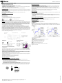
Marking according to ATEX specications
Manufacturer logo
Transmitter type
Measuring range
Output signal
Electrical connection
Traceability code and year
Kind of gasket if different from the NBR standard
The CE0081 logo and references which belongs to Intrisically Safe certication
On some models, the indication OX for use on oxygen according to ISO2503, MR max. 320 bar
Mounting
1- Mounting must be carried out in compliance with current regulations for process and installations classied in
hazardous areas. Before starting up, it is essential to check that the process and uid to be measured using the
transmitter are compatible with the requirements of Intrinsically Safe. The pressure and characteristics of the uid to
be measured must be compatible with the pressure switch (to eliminate all risk of damage or explosion). The uid must be
compatible with 1.4404 stainless steel (AISI 316L), AL203 ceramic material and the type of gasket.
The uid must be compatible with the components of the separator and the lling uid for models with separators.
The use of a pressure switch with a uid for which it has not been designed is strictly prohibited
2- The operating temperature and uid temperature must be -20 °C and class T6 or T5
Every precaution must be taken by the user to ensure that the heat transfer by the uid to the unit head does not
raise the unit head temperature to the spontaneous ignition temperature of the gas in which it is situated.
In the case of separator models, the temperature of the process must not give rise to a temperature in the pressure switch
higher than the allowed maximum.
3- The uid must not freeze inside the pressure switch. Nothing rigid must be allowed to enter the pressure port opening as it
may destroy the diaphragm. The mounting/dismounting operations must be carried out with the power switched off and at zero
pressure. Note, when the liquid is compressed during mounting, it may result in overpressure.
4- Leave all labels and markings visible.
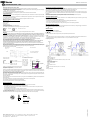
Certied safety barrier
Hazardous area
zone 0 1 2
Non hazardous area
Don’t forget the resistances of
barriers for determining Rc
YTED
5- The mounting position does not affect the measurement; it is nonetheless recommended to place the pressure switch away
from all severe environmental conditions (throbbing, hammer-blow in pipes, vibrations, jolts, sources of heat, electrical and
magnetic elds, lightning, humidity and atmospheric inuences).
The YTED threaded process connection pressure switch:
The operator must ensure that the connection is sealed. The sealing surface must be clean and an appropriate gasket used.
Use a 27 mm (1”1/16) wrench on the hexagon (G1/2, 1/2NPT) to tighten to the appropriate torque (50 Nm maximum). Reduce
this torque for smaller threads.
YTED with separator:
The operator must ensure the connections are sealed, by using the correct thread sealant or gaskets and are compatible with
the uid measured.
Do not modify, interfere with, or separate, the link between the pressure switch and the separator.
Do not separate the two parts of a separator with bolted anges.
Do not use the pressure switch as a means to tighten the connection.
Electrical connection :
The installer lmust respect the drawing’s prescriptions
Comply with the connection of the cable or connectors and the voltage values and load resistance.
When setting up the cable, you must comply with the following points:
- use a shielded cable and connect the shield to the 2 ends of the earth;
- do not leave surplus cable rolled up as this increases the inductance of the connection. Make a 10cm quadrant to avoid
run-off towards the pressure switch;
- do not expose the pressure switch to humidity without its connector;
- the pressure switch breathes through a sintered pellet on the back (atmospheric pressure for relative pressure switches
P < 25 bar). It must be kept dry.
The supply voltage must comply with the value shown on the equipment: Maximum 28 Vdc. The inputs/ouputs are electrically
isolated from the mechanical earth, the voltage between earth and wire must be lower than 75Vdc (50Vac).
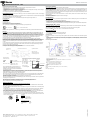
CONNECTION
Mobile plug
Pin 1 : + Supply
Pin 2 : Threshold 2
Pin 3 : - Supply
Pin 4 : Threshold 1
Pin 5 : Earth / Ground
Standard moulded cable
+ Supply : Brown
Threshold 2 : White
- Supply : Blue
Threshold 1 : Black
Earth / Ground : Grey
Disassembly, reassembly and maintenance
A qualied technician must perform the following procedure.
Before dismantling anything, make sure that the pressure switch is switched off, the hydraulic circuit is no longer under pres-
sure, and the ambient temperature allows you to dismantle the equipment without getting burnt.
Protect the tip of the pressure port against damage, especially where a diaphragm is tted.
When the equipment is being re-calibrated or checked, it is essential to assertain whether it is to be used on an oxygen circuit.
If so, a qualied technician who has been forewarned must perform these procedures, and is provided with the appropriate
equipment.
Do not reassemble the pressure switch using different uids (risk of chemical reaction and even explosion).
Reassembly: Observe the same regulations as those laid down for the initial assembly.
OPERATING INSTRUCTIONS
Each time the YTED digital pressure switch is switched on it runs a selftest procedure then goes into measuring mode, ready
to operate.
The front panel of the standard YTED is equipped with:
- 1 four-digit, seven-segment red LED display for pressure and operating parameter readout.
- 2 LEDs, S1 and S2, displaying the status of contacts 1 and 2.
- 3 touch keys to open the scrolling menu to display the settings of the various operating parameters.
MINI-MAXI PRESSURE DISPLAY
Pressing alternately displays min and max pressure measured from the time of start-up. Holding down for 5 seconds dur-
ing this function re-initialises therse values.
Press during this function to return to measuring mode.
USER SETTINGS
I. Key functions
:
1. "F" Menu access - Settings validation
2. and Menu selection - Adjusting the values
II. User menus
The "F" key displays the "CodE" message. The sequence to adjust different parameters is linear.
1. Code
Enter settings access code. If the correct value is entered ("1" is factory setting), parameters are accessible for modication and are
automatically saved when returning to Measurement mode. If not, they are accessible in read-only mode.
2. Adjusting thresholds
1. SP 1 - 2
Values threshold 1 and 2
2. tS 1 – 2 and tH 1- 2
Temporization values of hysteretic and threshold, step 0,1s from 0 to 25s
3. UPdo 1 - 2
Working mode threshold 1 and 2
"UP" : normally opened
"do" : normally closed
4. H 1-2
Values hysteretic 1 and 2
3. 0Aut
Zero offset at actual pressure level (max ± 10% Full Scale).
4. nCod
Setting access code
Pressure switch YTED
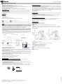
LCIE 03 ATEX 6300 X
I M1 Ex ia I Ma
II 1 G Ex ia IIC T6
or T5 Ga
-20°C ≤ Ta. ≤ +70°C Class T6 :Ta. + 40°C
Class T5 :Ta. +70°C
In area 0, the combination of the pressure switch and the
safety barrier must be covered by a calculation checked
by an approved organization
CE 0081
The installation must respect :
U max. : 28 Vdc
I max. : 120 mA
Po max. : 0,8 W
Ca > Ci + Ccable
La > Li + Lcable
Ci max : 13,2nF
Li : insignicant
Rc mini > 200 si 28 VDC
Rc max. =
600
800
Rc
0.02
V Alim -12
24
11
28
V
200
Zone d'utilisation
operating area
supply
USER INSTRUCTIONS - YTED
EN
Baumer Bourdon-Haenni S.A.S. · 125, rue de la Marre · B.P. 70214 · 41103 Vendôme Cedex · France
Tél. +33 (0)2 54 73 74 75 · Fax France +33 (0)2 54 73 74 74 · Fax Export +33 (0)2 54 73 74 73
sales.fr@baumer.com · www.baumer.com
320108 ind g 06/2012
I M1 Ex ia I Ma
II 1 G Ex ia IIC T6 or T5 Ga
Page is loading ...
Page is loading ...
-
 1
1
-
 2
2
-
 3
3
-
 4
4


Baumer TED Installation guide
- Category
- Measuring, testing & control
- Type
- Installation guide
- This manual is also suitable for
Ask a question and I''ll find the answer in the document
Finding information in a document is now easier with AI
in other languages
- français: Baumer TED Guide d'installation
- español: Baumer TED Guía de instalación
- Deutsch: Baumer TED Installationsanleitung
Related papers
-
Baumer CTX Installation guide
-
Baumer CTL Installation guide
-
-
-
Baumer PBSN Installation guide
-
-
-
-
-
Baumer PBMN high pressure Installation guide
Other documents
-
Renkforce EDWC2012 Owner's manual
-
sauermann Cost-S Quick start guide
-
-
Bauer FAN Separator Green Bedding User manual
-
Aldes EasyVEC Series User manual
-
Everbilt 72716 Specification
-
Emerson D Control Station Flameproof Certificate
-
-
Dwyer Series SA1100 User manual
-
WIKA PSD-3 Serie User manual