Desa Tech CCL3018PTA/NTA, CCL3924PTA/NTA, CCL3930PTB/NTB User manual
- Category
- Fireplaces
- Type
- User manual

Save this manual for future reference.
For more information, visit www.desatech.com
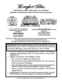
UNVENTED (VENT-FREE) GAS LOG HEATER
OWNER’S OPERATION AND INSTALLATION MANUAL
Biltmore Split Oak, Seasonal Oak and Smoky Mountain Oak Logs
Variable Manually-Controlled Models Also
Design-Certified As Vented Decorative Appliances
18", 24" AND 30" VARIABLE
MANUALLY-CONTROLLED
MODELS
CRL2718PA/NA
CRL3124PA/NA
CCL3018PA/NA
CCL3924PA/NA
18", 24" AND 30"
THERMOSTATICALLY-CONTROLLED
MODELS
CCL3018PTA/NTA
CCL3924PTA/NTA
CCL3930PTB/NTB
WARNING: If the information in this manual is not fol-
lowed exactly, a fire or explosion may result causing
property damage, personal injury or loss of life.
— Do not store or use gasoline or other flammable
vapors and liquids in the vicinity of this or any other
appliance.
— WHAT TO DO IF YOU SMELL GAS
• Do not try to light any appliance.
• Do not touch any electrical switch; do not use any
phone in your building.
•
Immediately call your gas supplier from a neighbor’s
phone. Follow the gas supplier’s instructions.
• If you cannot reach your gas supplier, call the fire
department.
— Installation and service must be performed by a quali-
fied installer, service agency or the gas supplier.
Patent Pending
P
I
L
O
T
O
F
F
O
N
L
O
R
E
M
O
T
E
O
F
F
H
I

www.desatech.com
113097-01D
2
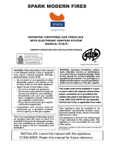
WARNING: Improper installation, adjustment, altera-
tion, service or maintenance can cause injury or prop-
erty damage. Refer to this manual for correct installation
and operational procedures. For assistance or addi-
tional information consult a qualified installer, service
agency or the gas supplier.
WARNING: This appliance is for installation only in a
solid-fuel burning masonry or UL127 factory-built fire-
place or in a listed ventless firebox enclosure. It is de-
sign-certified for these installations in accordance with
ANSI Z21.11.2. Exception: Do not install this appliance
in a factory-built fireplace that includes instructions
stating it has not been tested or should not be used with
unvented gas logs.
WARNING: This is an unvented gas-fired heater. It uses
air (oxygen) from the room in which it is installed. Provi-
sions for adequate combustion and ventilation air must
be provided. Refer to Air for Combustion and Ventilation
section on page 5 of this manual.
This appliance may be installed in an aftermarket,* per-
manently located, manufactured (mobile) home, where
not prohibited by local codes.
This appliance is only for use with the type of gas indi-
cated on the rating plate. This appliance is not convert-
ible for use with other gases.
* Aftermarket: Completion of sale, not for purpose of resale, from the manufacturer
TABLE OF CONTENTS
Safety Information ............................................... 3
Local Codes ........................................................ 4
Product Identification ...........................................
5
Unpacking ........................................................... 5
Product Features ................................................. 5
Air for Combustion and Ventilation ...................... 5
Installation ........................................................... 8
Operating Heater ............................................... 19
Inspecting Burners ........................................... 23
Cleaning and Maintenance ................................ 23
Service Hints ..................................................... 24
Technical Service ..............................................
24
Troubleshooting .................................................
25
Optional Positioning of Thermostat Sensing Bulb
.. 28
Specifications ....................................................
29
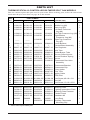
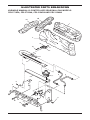
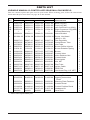
Illustrated Parts Breakdown and Parts List ....... 30
Replacement Parts ............................................ 38
Accessories ....................................................... 38
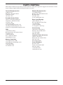
Parts Central ..................................................... 39
Warranty Information ...........................
Back Cover

www.desatech.com
113097-01D 3
SAFETY INFORMATION
WARNING: This product con-
tains and/or generates chemicals
known to the state of California
to cause cancer or birth defects
or other reproductive harm.
IMPORTANT: Read this owner’s
manual carefully and completely
before trying to assemble,
operate or service this heater.
Improper use of this heater can
cause serious injury or death
from burns, fire, explosion,
electrical shock and carbon
monoxide poisoning.
DANGER: Carbon monoxide
poisoning may lead to death!
Carbon Monoxide Poisoning: Early signs of carbon
monoxide poisoning resemble the flu, with head
-
aches, dizziness or nausea. If you have these signs,
the heater may not be working properly. Get fresh
air at once! Have heater serviced. Some people
are more affected by carbon monoxide than others.
These include pregnant women, people with heart
or lung disease or anemia, those under the influence
of alcohol and those at high altitudes.
Natural and Propane/LP Gas: Natural and pro-
pane/LP gases are odorless. An odor-making agent
is added to the gas. The odor helps you detect a gas
leak. However, the odor added to the gas can fade.
Gas may be present even though no odor exists.
Make certain you read and understand all warn
-
ings. Keep this manual for reference. It is your
guide to safe and proper operation of this heater.
WARNING: Any change to
this heater or its controls can
be dangerous.
WARNING: Do not allow fans
to blow directly into the fireplace.
Avoid any drafts that alter burner
flame patterns. Ceiling fans can
create drafts that alter burner
flame patterns. Altered burner
patterns can cause sooting.
WARNING: Do not use a blow-
er insert, heat exchanger insert
or other accessory not approved
for use with this heater.
Due to high temperatures, the
appliance should be located out
of traffic and away from furniture
and draperies.
Do not place clothing or other
flammable material on or near
the appliance. Never place any
objects on the heater.
Heater base assembly becomes
very hot when running heater.
Keep children and adults away
from hot surface to avoid burns
or clothing ignition. Heater
will remain hot for a time after
shutdown. Allow surface to cool
before touching.
Carefully supervise young chil-
dren when they are in the room
with heater.
You must operate this heater
with a fireplace screen in place.
Make sure fireplace screen is
closed before running heater.
Keep the appliance area clear
and free from combustible ma
-
terials, gasoline and other flam-
mable vapors and liquids.
1. This appliance is only for use with the type
of gas indicated on the rating plate. This ap
-
pliance is not convertible for use with other
gases.
2. Do not place propane/LP supply tank(s) inside
any structure. Locate propane/LP supply
tank(s) outdoors (propane/LP units only).
3. To prevent performance problems, do not use
propane/LP fuel tank of less than 100 lbs.
capacity (propane/LP units only).

www.desatech.com
113097-01D
4
4. If you smell gas
• shut off gas supply
• do not try to light any appliance
• do not touch any electrical switch; do not
use any phone in your building
• immediately call your gas supplier from
a neighborʼs phone. Follow the gas
supplierʼs instructions
• if you cannot reach your gas supplier, call
the fire department
5. This heater shall not be installed in a bedroom
or bathroom unless installed as a vented appli
-
ance (Variable Manually-Controlled Models
Only) (see Installing Damper Clamp Acces-
sory for Vented Operation, page 11).
6. Before installing in a solid fuel burning
fireplace, the chimney flue and firebox must
be cleaned of soot, creosote, ashes and loose
paint by a qualified chimney cleaner. Creosote
will ignite if highly heated. A dirty chimney
flue may create and distribute soot within
the house. Inspect chimney flue for damage.
If damaged, repair flue and firebox before
operating heater.
7. Do not burn solid-fuel in a masonry or UL127
factory-built fireplace in which a vent-free
room heater is installed.
8.
If fireplace has glass doors, never operate this
heater with glass doors closed. If you operate
heater with doors closed, heat buildup inside fire-
place will cause glass to burst. Make sure there are
no obstructions across openings of fireplace.
9.
This log heater is designed to be smokeless. If
logs ever appear to smoke, turn off heater and
call a qualified service person. Note: During
initial operation, slight smoking could occur
due to log curing and heater burning manufac-
turing residues.
10.
To prevent the creation of soot, follow the instruc-
tions in Cleaning and Maintenance, page 23.
11. Before using furniture polish, wax, carpet
cleaner or similar products, turn heater off. If
heated, the vapors from these products may
create a white powder residue within burner
box or on adjacent walls or furniture.
12. This heater needs fresh, outside air ventilation
to run properly. This heater has an Oxygen De
-
pletion Sensing (ODS) safety shutoff system.
The ODS shuts down the heater if not enough
fresh air is available. See Air for Combustion
and Ventilation, page 5. If heater keeps shutting
off, see Troubleshooting, page 25.
13. Do not run heater
• where flammable liquids or vapors are
used or stored
• under dusty conditions
14. Do not use this heater to cook food or burn
paper or other objects.
15. Do not use heater if any part has been exposed
to or under water. Immediately call a qualified
service technician to inspect the room heater
and to replace any part of the control system and
any gas control which has been under water.
16. Do not operate heater if any log is broken. Do
not operate heater if a log is chipped (dime-
sized or larger).
17. Turn heater off and let cool before servicing.
Only a qualified service person should service
and repair heater.
18. Operating heater above elevations of 4,500
feet could cause pilot outage.
19.
Provide adequate clearances around air
openings.
LOCAL CODES
Install and use heater with care. Follow all local
codes. In the absence of local codes, use the lat
-
est edition of The National Fuel Gas Code, ANSI
Z223.1/NFPA 54*.
*Available from:
American National Standards Institute, Inc.
1430 Broadway
New York, NY 10018
National Fire Protection Association, Inc.
Batterymarch Park
Quincy, MA 02269
Note: Where listed vented decorative logs are
required, thermostat operation is not permitted.
SAFETY INFORMATION
Continued
State of Massachusetts: The installa-
tion must be made by a licensed plumber
or gas fitter in the Commonwealth of
Massachusetts.
Sellers of unvented propane or natural
gas-fired supplemental room heaters shall
provide to each purchaser a copy of 527
CMR 30 upon sale of the unit.
Vent-free gas products are prohibited for
bedroom and bathroom installation in the
Commonwealth of Massachusetts.

www.desatech.com
113097-01D 5
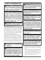
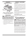
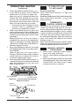
Figure 1 - Vent-Free Gas Log Heater
(Logs May Vary by Model, Seasonal Oak
Single Burner Model Shown)
Base
Grate
Log Set
Control Knob
Burner
Piezo
Ignitor
PRODUCT
IDENTIFICATION
PRODUCT FEATURES
OPERATION
This heater is clean burning. It requires no outside
venting. There is no heat loss out a vent or up a
chimney. Heat is generated by realistic dancing,
yellow flames. This heater is designed for vent-free
operation with flue damper closed. It has been
tested and approved to ANSI Z21.11.2 standard
for unvented heaters. State and local codes in some
areas prohibit the use of vent-free heaters. This
heater may also be operated as a vented decorative
(ANSI Z21.60) product by opening the flue damper
(non-thermostat operation only).
SAFETY PILOT
This heater has a pilot with an Oxygen Deple-
tion Sensing (ODS) safety shutoff system. The
ODS/pilot is a required feature for vent-free room
heaters. The ODS/pilot shuts off the heater if there
is not enough fresh air.
PIEZO IGNITION SYSTEM
This heater has a piezo ignitor. This system re-
quires no matches, batteries or other sources to
light heater.
AIR FOR COMBUSTION
AND VENTILATION
WARNING: This heater shall
not be installed in a confined
space or unusually tight con-
struction unless provisions are
provided for adequate combus
-
tion and ventilation air. Read the
following instructions to insure
proper fresh air for this and
other fuel-burning appliances
in your home.
Todayʼs homes are built more energy efficient
than ever. New materials, increased insulation and
new construction methods help reduce heat loss
in homes. Home owners weather strip and caulk
around windows and doors to keep the cold air out
and the warm air in. During heating months, home
owners want their homes as airtight as possible.
While it is good to make your home energy effi
-
cient, your home needs to breathe. Fresh air must
enter your home. All fuel-burning appliances need
fresh air for proper combustion and ventilation.
UNPACKING
CAUTION: Do not remove
the data plates from the grate as-
sembly. The data plates contain
important product information.
1. Remove logs and heater base assembly from
carton. Note: Do not pick up heater base as-
sembly by burners. This could damage heater.
Always handle base assembly by grate.
2. Remove all protective packaging applied to
logs and heater for shipment.
3. Check all items for any shipping damage. If
damaged, promptly inform dealer where you
bought heater.

www.desatech.com
113097-01D
6
Exhaust fans, fireplaces, clothes dryers and fuel
burning appliances draw air from the house to
operate. You must provide adequate fresh air for
these appliances. This will insure proper venting
of vented fuel-burning appliances.
PROVIDING ADEQUATE
VENTILATION
The following are excerpts from National Fuel
Gas Code, ANSI Z223.1/NFPA 54, Section 5.3,
Air for Combustion and Ventilation.
All spaces in homes fall into one of the three fol
-
lowing ventilation classifications:
1. Unusually Tight Construction
2. Unconfined Space
3. Confined Space
The information on pages 5 through 7 will help
you classify your space and provide adequate
ventilation.
Unusually Tight Construction
The air that leaks around doors and windows
may provide enough fresh air for combustion and
ventilation. However, in buildings of unusually
tight construction, you must provide additional
fresh air.
Unusually tight construction is defined
as construction where:
a. walls and ceilings exposed to the out-
side atmosphere have a continuous
water vapor retarder with a rating of
one perm (6x10
-11
kg per pa-sec-m
2
) or
less with openings gasketed or sealed
and
b. weather stripping has been added on
openable windows and doors and
c. caulking or sealants are applied to
areas such as joints around window
and door frames, between sole plates
and floors, between wall-ceiling joints,
between wall panels, at penetrations
for plumbing, electrical and gas lines
and at other openings.
If your home meets all of the three criteria
above, you must provide additional fresh
air. See Ventilation Air From Outdoors
,
page 7.
If your home does not meet all of the three
criteria above, proceed to Determining
Fresh-Air Flow for Heater Location.
Confined and Unconfined Space
National Fuel Gas Code, ANSI Z223.1/NFPA
54 defines a confined space as a space whose
volume is less than 50 cubic feet per 1,000 Btu
per hour (4.8 m
3
per kw) of the aggregate input
rating of all appliances installed in that space and
an unconfined space as a space whose volume is
not less than 50 cubic feet per 1,000 Btu per hour
(4.8 m
3
per kw) of the aggregate input rating of
all appliances installed in that space. Rooms com
-
municating directly with the space in which the
appliances are installed*, through openings not
furnished with doors, are considered a part of the
unconfined space.
* Adjoining rooms are communicating only if
there are doorless passageways or ventilation grills
between them.
DETERMINING FRESH-AIR FLOW
FOR HEATER LOCATION
Determining if You Have a Confined or
Unconfined Space
Use this work sheet to determine if you have a
confined or unconfined space.
Space: Includes the room in which you will install
fireplace plus any adjoining rooms with doorless pas-
sageways or ventilation grills between the rooms.
1. Determine the volume of the space (length x
width x height).
Length x Width x Height =__________cu. ft.
(volume of space)
Example: Space size 20 ft. (length) x 16 ft.
(width) x 8 ft. (ceiling height) = 2,560 cu. ft.
(volume of space)
If additional ventilation to adjoining room is
supplied with grills or openings, add the volume
of these rooms to the total volume of the space.
2. Multiply the space volume by 20 to determine
the maximum Btu/Hr the space can support.
__________ (volume of space) x 20 = (Maxi-
mum Btu/Hr the space can support)
Example: 2,560 cu. ft. (volume of space) x 20 =
51,200 (maximum Btu/Hr the space can support)
3. Add the Btu/Hr of all fuel burning appliances in
the space.
Vent-free fireplace
__________ Btu/Hr
Gas water heater*
__________ Btu/Hr
Gas furnace
__________ Btu/Hr
Vented gas heater
__________ Btu/Hr
Gas fireplace logs
__________ Btu/Hr
Other gas appliances* + ________
Btu/Hr
Total = ________
Btu/Hr
* Do not include direct-vent gas appliances. Di
-
rect-vent draws combustion air from the outdoors
and vents to the outdoors.
AIR FOR COMBUSTION
AND VENTILATION
Continued

www.desatech.com
113097-01D 7
Example:
Gas water heater ____________
Btu/Hr
Vent-free fireplace + ___________
Btu/Hr
Total = ___________
Btu/Hr
4. Compare the maximum Btu/Hr the space can
support with the actual amount of Btu/Hr used.
_________
Btu/Hr (maximum the space can support)
_________
Btu/Hr (actual amount of Btu/Hr used)
Example: 51,200 Btu/Hr (maximum the space
can support)
79,000 Btu/Hr (actual amount of
Btu/Hr used)
The space in the example is a confined space because
the actual Btu/Hr used is more than the maximum
Btu/Hr the space can support. You must provide ad
-
ditional fresh air. Your options are as follows:
A. Rework worksheet, adding the space of an adjoin
-
ing room. If the extra space provides an unconfined
space, remove door to adjoining room or add
ventilation grills between rooms. See Ventilation
Air From Inside Building.
B. Vent room directly to the outdoors. See Ventila
-
tion Air From Outdoors.
C. Install a lower Btu/Hr fireplace, if lower Btu/Hr
size makes room unconfined.
If the actual Btu/Hr used is less than the maximum
Btu/Hr the space can support,
the space is an un-
confined space. You will need no additional fresh
air ventilation.
WARNING: If the area in
which the heater may be oper-
ated is smaller than that defined
as an unconfined space or if the
building is of unusually tight
construction, provide adequate
combustion and ventilation air
by one of the methods described
in the National Fuel Gas Code,
ANSI Z223.1/NFPA 54 Section 5.3
or applicable local codes.
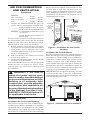
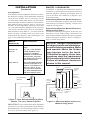
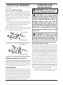
VENTILATION AIR
Ventilation Air From Inside Building
This fresh air would come from an adjoining un
-
confined space. When ventilating to an adjoining
unconfined space, you must provide two perma
-
nent openings: one within 12" of the ceiling and
one within 12" of the floor on the wall connecting
the two spaces (see options 1 and 2, Figure 2). You
can also remove door into adjoining room (see
option 3, Figure 2). Follow the National Fuel Gas
Code, ANSI Z223.1/NFPA 54, Section 5.3, Air for
Combustion and Ventilation for required size of
ventilation grills or ducts.
AIR FOR COMBUSTION
AND VENTILATION
Continued
40,000
39,000
79,000
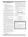
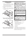
Figure 3 - Ventilation Air from Outdoors
Figure 2 - Ventilation Air from Inside
Building
Outlet
Air
Ventilated
Attic
Outlet
A
ir
Inlet
Air
Inlet Air
Ventilated
Crawl Space
To
Crawl
Space
To Attic
Or
Remove
Door into
Adjoining
Room,
Option
3
Ventilation Grills
Into Adjoining Room,
Option
2
Ve
ntilation
Grills
Into Adjoining
Room,
Option 1
12"
12"
Ventilation Air From Outdoors
Provide extra fresh air by using ventilation grills or
ducts. You must provide two permanent openings:
one within 12" of the ceiling and one within 12"
of the floor. Connect these items directly to the
outdoors or spaces open to the outdoors. These
spaces include attics and crawl spaces. Follow the
National Fuel Gas Code, ANSI Z223.1/NFPA 54,
Section 5.3, Air for Combustion and Ventilation for
required size of ventilation grills or ducts.
IMPORTANT: Do not provide openings for inlet
or outlet air into attic if attic has a thermostat-
controlled power vent. Heated air entering the attic
will activate the power vent.

www.desatech.com
113097-01D
8
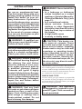
INSTALLATION
NOTICE: This heater is intended
for use as supplemental heat.
Use this heater along with your
primary heating system. Do not
install this heater as your pri-
mary heat source. If you have a
central heating system, you may
run system’s circulating blower
while using log heater. This will
help circulate the heat from your
log heater throughout the house.
In the event of a power outage,
you can use this heater as your
primary heat source.
WARNING: A qualified ser-
vice person must install heater.
Follow all local codes.
NOTICE: State or local codes may
only allow operation of this appli-
ance in a vented configuration.
Check your state or local codes.
WARNING: Before installing
in a solid fuel burning fireplace,
the chimney flue and firebox
must be cleaned of soot, creo-
sote, ashes and loose paint by
a qualified chimney cleaner.
Creosote will ignite if highly
heated. A dirty chimney flue may
create and distribute soot within
house. Inspect chimney flue and
firebox for damage. If damaged,
repair flue and firebox before
operating heater.
WARNING: Seal any fresh
air vents or ash clean-out doors
located on floor or wall of fire
-
place. If not, drafting may cause
pilot outage or sooting. Use a
heat-resistant sealant. Do not
seal chimney flue damper.
WARNING: Never install the
heater
• in a bedroom or bathroom
unless installed as a vented
appliance (Variable Manually-
Controlled Models Only) (see
page 11)
• in a recreational vehicle
• where curtains, furniture,
clothing or other flammable
objects are less than 42 inches
from the front, top or sides of
the heater
• in high traffic areas
• in windy or drafty areas
CAUTION: This heater cre-
ates warm air currents. These
currents move heat to wall sur-
faces next to heater. Installing
heater next to vinyl or cloth wall
coverings or operating heater
where impurities (such as, but
not limited to, tobacco smoke,
aromatic candles, cleaning flu-
ids, oil or kerosene lamps, etc.) in
the air exist, may discolor walls
or cause odors.
IMPORTANT: Vent-free heaters add moisture to
the air. Although this is beneficial, installing heater
in rooms without enough ventilation air may cause
mildew to form from too much moisture. See Air
for Combustion and Ventilation
, page 5.
CHECK GAS TYPE
Use the correct gas type (natural or propane/LP)
for your unit. If your gas supply is not correct, do
not install heater. Call dealer where you bought
heater for proper type heater.
WARNING: This appliance
is equipped for (natural or pro-
pane/LP) gas. Field conversion
is not permitted.

www.desatech.com
113097-01D 9
INSTALLATION AND CLEARANCES
(Vent-Free Operation Only
)
WARNING: Maintain the
minimum clearances. If you
can, provide greater clearances
from floor, ceiling and adjoining
wall.
MINIMUM FIREPLACE CLEARANCE
TO COMBUSTIBLE MATERIALS
Log Size Side Wall Ceiling
18", 24", 30" 16" 42"
LOG SIZING REQUIREMENTS
Minimum Firebox
Log Front Rear *
Size Height Depth Width Width
18" 17" 14" 24" 20"
24" 17" 14" 28" 21"
30" 17" 14" 34" 24"
* Measured at 14" depth.
Carefully follow the instructions below. This will
ensure safe installation into a masonry, UL127-
listed manufactured fireplace or certified vent-free
firebox.
Minimum Clearances For Side
Combustible Material, Side Wall and
Ceiling
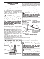
A. Clearances from the side of the fireplace
cabinet to any combustible material and wall
should follow diagram in Figure 4.
Example: The face of a mantel, bookshelf,
etc. is made of combustible material and
protrudes 3
1
/2" from the wall. This combus-
tible material must be 4" from the side of the
fireplace opening (see Figure 4).
Note: When installing your gas logs into
a manufactured firebox, follow firebox
manufacturerʼs instructions for minimum
clearances to combustible materials.
B. Clearances from the top of the fireplace opening
to the ceiling should not be less than 42 inches.
INSTALLATION
Continued
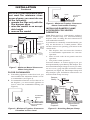
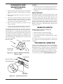
Figure 4 - Minimum Clearance for
Combustible to Wall
*Minimum 16 inches from Side Wall
Example
*
NOTICE: Manual control heaters
may be used as a vented product.
If so, you must always run heater
with chimney flue damper open.
If running heater with damper
open, noncombustible material
above fireplace opening is not
needed. Go to Installing Damper
Clamp Accessory for Vented
Operation, page 11.
Minimum Noncombustible Material
Clearances
If Not Using Mantel
Note: If using a mantel, proceed to If Using
Mantel, page 10. If not using a mantel, follow the
information below.
You must have noncombustible material(s) above
the fireplace opening. Noncombustible materials
(such as slate, marble, tile, etc.) must be at least
1/2 inch thick. With sheet metal, you must have
noncombustible material behind it. Noncombus
-
tible material must extend at least 8" up (for all
models). If noncombustible material is less than
12", you must install the fireplace hood accessory
(24" and 30" models only). See Figure 5, page 10
for minimum clearances.
IMPORTANT: If you cannot meet these minimum
clearances, you must operate heater with chimney
flue damper open. Go to Installing Damper Clamp
Accessory for Vented Operation, page 11.

www.desatech.com
113097-01D
10
If Using Mantel
You must have noncombustible material(s) above
the fireplace opening. Noncombustible materials
(such as slate, marble, tile, etc.) must be at least
1/2 inch thick. With sheet metal, you must have
noncombustible material behind it. Noncombus-
tible material must extend at least 8" up (for all
models). If noncombustible material is less than
12", you must install the fireplace hood accessory
(24" and 30" models only). Even if noncombus
-
tible material is more than 12", you may need the
hood accessory to deflect heat away from your
mantel shelf. See Figure 5 and 6 and Figure 7 on
page 11 for minimum clearances.
MANTEL CLEARANCES
In addition to meeting noncombustible material
clearances, you must also meet required clearances
between fireplace opening and mantel shelf. If
you do not meet the clearances in Figure 6 you
will need a hood.
Determining Minimum Mantel Clearance
If you meet minimum clearance between mantel
shelf and top of fireplace opening, a hood is not
required (see Figure 6).
Determining Minimum Mantel Clearance
When Using a Hood
If minimum clearances in Figure 6 are not met, you
must have a hood. When using a hood there are
still certain minimum mantel clearances required.
Follow minimum clearances shown in Figure 7,
page 11 when using hood.
NOTICE: Surface temperatures
of adjacent walls and mantels be-
come hot during operation. Walls
and mantels above the firebox
may become hot to the touch.
If installed properly, these tem-
peratures meet the requirement
of the national product standard.
Follow all minimum clearances
shown in this manual.
INSTALLATION
Continued
Noncombustible Requirements for
Material Safe Installation
Distance (A)
12" or more Noncombustible material
okay.
Between 8" 24", 30" or 36" Models:
and 12" Install fireplace hood
accessory (GA6050,
GA6052 or GA6053 see
Accessories, page 38).
18" Model: Noncombus-
tible material okay.
Less than 8" Noncombustible material
must be extended to at
least 8". See Between 8"
and 12", above. If you
cannot extend material,
you must operate heater
with flue damper open.
IMPORTANT: If you cannot meet these minimum
clearances, you must operate heater with chimney
flue damper open. Go to Installing Damper Clamp
Accessory for Vented Operation, page 11.
Heat Resistant
Material
(A)
Figure 5 - Heat Resistant Material (Slate,
Marble, Tile, etc.) Above Fireplace
Figure 6 - Minimum Mantel Clearances
Without Using Hood
Minimum
Noncombustible
Material
Minimum
Noncombustible
Material Height
Distances to
Underside of
Mantel
Top of Fireplace
Opening
Underside
of Mantel
Shelf
Mantel Shelf
12"
8"
(A)
18"
8"
20"
14"
22"
17"
24"
20"
All minimum
distances
are in inches
Log Set
24"/30"
Models
18" Model
2
1
/2
"
6"
8"
10"

www.desatech.com
113097-01D 11
NOTICE: If your installation does
not meet the minimum clear-
ances shown, you must do one
of the following:
• operate the logs only with the
flue damper open
• raise the mantel to an accept-
able height
• remove the mantel
INSTALLATION
Continued
Minimum
Noncombustible
Material
8"
Min.
12"
15"
18"
All minimum
distances are
in inches
Log Set
18", 24",
30" Models
20"
2
1
/2"
6"
8"
10"
12"
Distances to
Underside of
Mantel
Hood
(GA6050
,
GA6052
)
Top of
Fireplace
Openin
g
Underside
of Mantel
Shel
f
Mantel Shel
f
Figure 7 - Minimum Mantel Clearances
When Using Hood
(GA6050,
GA6052 and
GA6053)
All
Models
14"
Min.
Combustible
Material
Noncombustible
Material
Hearth
5"
Min.
Combustible
Material
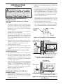
Figure 9 - Minimum Fireplace Clearances
Above Combustible Flooring
Figure 8 - Minimum Fireplace Clearances
if Installed at Floor Level
Figure 10 - Attaching Damper Clamp
Manufactured
Fireplace
Masonry
Fireplace
Damper
Damper
Clamp
Damper
Damper
Clamp
Damper
FLOOR CLEARANCES
A. If installing appliance on the floor level, you
must maintain the minimum distance of 14"
to combustibles (see Figure 8).
B. If combustible materials are less than 14" to
the fireplace, you must install appliance at
least 5" above the combustible flooring (see
Figure 9).
INSTALLING DAMPER CLAMP
ACCESSORY FOR VENTED
OPERATION
Note: When used as a vented heater, appliance
must be installed only in a solid-fuel burning
fireplace with a working flue and constructed of
noncombustible material.
If your heater is a manually-controlled model, you
may use this heater as a vented product. There
are three reasons for operating your heater in the
vented mode.
1. The fireplace does not meet the clearance
to combustibles requirements for vent-free
operation.
2. State or local codes do not permit vent-free
operation.
3. You prefer vented operation.
If reasons number 1 or 2 above apply to you, you
must permanently open chimney flue damper. You
must install the damper clamp accessory (to order,
see Accessories, page 38). This will insure vented
operation (see Figure 10). The damper clamp will
keep damper open. Installation instructions are
included with clamp accessory.

www.desatech.com
113097-01D
12
See chart below for minimum permanent flue
opening you must provide. Attach damper clamp
so the minimum permanent flue opening will be
maintained at all times.
INSTALLATION
Continued
INSTALLING HEATER BASE
ASSEMBLY
CAUTION: Do not remove the
data plates attached to the heater
base assembly. The data plates
contain important warranty and
safety information.
WARNING: You must secure
this heater to fireplace floor. If
not, heater will move when you
adjust controls. Moving heater
may cause a gas leak.
WARNING: If installing in a
sunken fireplace, special care
is needed. You must raise the
fireplace floor to allow access
to heater control panel. This
will insure adequate air flow
and guard against sooting and
controls being damaged. Raise
fireplace floor with noncombus-
tible material. Make sure material
is secure.
CAUTION: Do not pick up
heater base assembly by the
burner. This could damage
heater. Only handle base as
-
sembly by grates.
IMPORTANT: Make sure the heater burners are
level. If heater is not level, heater will not work
properly. For thermostat models, avoid damage
to thermostat bulb. Avoid nicks or sharp bends
in thermostat bulb wire. Keep thermostat bulb
in mounting bracket until ready to mount base
to floor. See Optional Positioning Of Thermostat
Sensing Bulb, page 28.
Installation Items Needed
• hardware package (provided with heater)
• approved flexible gas hose (not provided) (if
allowed by local codes)
• sealant resistant to propane (propane/LP) gas,
not provided
• electric drill with 3/16" drill bit
• flathead screwdriver
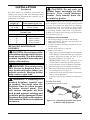
1. Apply pipe joint sealant lightly to male threads
of the fitting to be threaded into gas regulator.
Connect approved flexible gas hose to gas
regulator of heater (see Figure 11).
IMPORTANT: Hold gas regulator with
wrench when connecting flexible gas hose.
2. Locate masonry screws in hardware package.
3. Position heater base assembly in fireplace.
4. Place logs in their proper position on heater base,
see
Installing Logs on page 16.
5. Center heater base and logs front-to-back and
side-to-side in fireplace.
6. Carefully remove logs without moving heater
base.
Area of Various Standard
Round Flues
Diameter (in.) Area (sq. in.)
5" 20 sq. inches
6" 29 sq. inches
7" 39 sq. inches
8" 51 sq. inches
Chimney Minimum Permanent
Height (ft.) Flue Opening (sq. in.)
6' to 15' 39 sq. inches
15' to 30' 29 sq. inches
Figure 11 - Attaching Flexible Gas Hose
to Heater Gas Regulator
Heater Gas
Regulator
Flexible Gas Hose
(if allowed by local codes)
Fitting

www.desatech.com
113097-01D 13
INSTALLATION
Continued
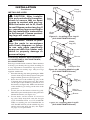
7. Mark screw locations through holes in mount-
ing brackets (see Figure 12 and 13). If install
-
ing in a brick-bottom fireplace, mark screw
locations in mortar joint of bricks.
8. Remove heater base from fireplace.
9. Drill holes at marked locations using 3/16"
drill bit.
10. Attach base assembly to fireplace floor using
two masonry screws (in hardware package)
(see Figure 12 or 13).
Figure 12 - Attaching Base Assembly to
Fireplace Floor - Dual Burner Model
Masonry
Screw
Mounting
Bracket
Masonry
Screw
Figure 13 - Attaching Base Assembly to
Fireplace Floor - Single Burner Model
Mounting
Bracket
CONNECTING TO GAS SUPPLY
WARNING: This appliance
requires a 1/2" NPT (National
Pipe Thread) inlet connection to
the pressure regulator.
WARNING: A qualified ser-
vice person must connect heater
to gas supply. Follow all local
codes.
CAUTION: Never connect
heater directly to the propane/LP
supply. This heater requires an
external regulator (not supplied).
Install the external regulator be-
tween the heater and propane/LP
supply.
WARNING: Never connect
natural gas fireplace to private
(non-utility) gas wells. This
gas is commonly known as
wellhead gas.
Installation Items Needed
Before installing heater, make sure you have the
items listed below.
• external regulator (supplied by installer)
• piping (check local codes)
• sealant (resistant to propane/LP gas)
• equipment shutoff valve *
• test gauge connection *
• sediment trap
• tee joint
• pipe wrench
* A CSA design-certified equipment shutoff valve
with 1/8" NPT tap is an acceptable alternative to
test gauge connection. Purchase the optional CSA
design-certified equipment shutoff valve from your
dealer. See Accessories, page 38.

www.desatech.com
113097-01D
14
For propane/LP units, the installer must supply
an external regulator. The external regulator will
reduce incoming gas pressure. You must reduce
incoming gas pressure to between 11 and 14 inches
of water. If you do not reduce incoming gas pres
-
sure, heater regulator damage could occur. Install
external regulator with the vent pointing down
as shown in Figure 14. Pointing the vent down
protects it from freezing rain or sleet.
CAUTION: Use only new,
black iron or steel pipe. Inter-
nally-tinned copper tubing may
be used in certain areas. Check
your local codes. Use pipe of
1/2" diameter or greater to allow
proper gas volume to heater. If
pipe is too small, undue loss of
volume will occur.
Installation must include an equipment shutoff
valve, union and plugged 1/8" NPT tap. Locate NPT
tap within reach for test gauge hook up. NPT tap
must be upstream from heater (see Figure 15).
IMPORTANT: Install equipment valve in an acces
-
sible location. The equipment shutoff valve is for
turning on or shutting off the gas to the appliance.
Check your building codes for any special re
-
quirements for locating equipment shutoff valve
to fireplaces.
Apply pipe joint sealant lightly to male NPT
threads. This will prevent excess sealant from
going into pipe. Excess sealant in pipe could result
in clogged heater valves.
WARNING: Use pipe joint
sealant that is resistant to liquid
petroleum (LP) gas.
We recommend that you install a sediment trap in
supply line as shown in Figure 15. Locate sediment
trap where it is within reach for cleaning. Install
in piping system between fuel supply and heater.
Locate sediment trap where trapped matter is not
likely to freeze. A sediment trap traps moisture and
contaminants. This keeps them from going into
heater controls. If sediment trap is not installed or
is installed wrong, heater may not run properly.
CAUTION: Avoid damage
to regulator. Hold gas regulator
with wrench when connecting it
to gas piping and/or fittings.
INSTALLATION
Continued
Figure 15 - Gas Connection
* Purchase the optional CSA design-certified
equipment shutoff valve from your dealer. See
Accessories, page 38.
** Minimum inlet pressure for purpose of input
adjustment.
3" Minimum
Sediment Trap
Gas
Regulator
CSA Design-
Certified Equipment
Shutoff Valve With
1/8" NPT Tap*
Approved Flexible
Gas Hose (if allowed
by local codes)
Tee Pipe Cap
Joint Nipple
Figure 14 - External Regulator With Vent
Pointing Down
Propane/LP
Supply Tank
External
Regulator
Vent
Pointing
Down
PROPANE/LP
From External
Regulator (11" W.C.**
to 14" W.C. Pressure)
NATURAL
From Gas Meter
(5" W.C.** to
10.5" W.C.
Pressure)
CHECKING GAS CONNECTIONS
WARNING: Test all gas pip-
ing and connections, internal
and external to unit, for leaks
after installing or servicing. Cor-
rect all leaks at once.
WARNING: Never use an open
flame to check for a leak. Apply a
noncorrosive leak detection fluid
to all joints. Bubbles forming show
a leak. Correct all leaks at once.

www.desatech.com
113097-01D 15
INSTALLATION
Continued
CAUTION: Make sure exter-
nal regulator has been installed
between propane/LP supply and
heater. See guidelines under Con-
necting to Gas Supply, page 13.
PRESSURE TESTING GAS SUPPLY
PIPING SYSTEM
Test Pressures In Excess Of 1/2 PSIG
(3.5 kPa)
1. Disconnect appliance with its appliance main
gas valve (control valve) and equipment
shutoff valve from gas supply piping system.
Pressures in excess of 1/2 psig will damage
heater regulator.
2. Cap off open end of gas pipe where equipment
shutoff valve was connected.
3. Pressurize supply piping by either opening
propane/LP supply tank valve for propane/LP
gas or opening main gas valve located on or
near gas meter for natural gas or using com
-
pressed air.
4. Check all joints of gas supply piping system.
Apply a noncorrosive leak detection fluid to
all joints. Bubbles forming show a leak.
5. Correct all leaks at once.
6. Reconnect heater and equipment shutoff valve
to gas supply. Check reconnected fittings for
leaks.
Test Pressures Equal To or Less Than
1/2 PSIG (3.5 kPa)
1. Close equipment shutoff valve (see Figure 16).
2. Pressurize supply piping system by either
opening propane/LP supply tank valve for
propane/LP gas or opening main gas valve
located on or near gas meter for natural gas
or using compressed air.
3. Check all joints from gas meter to equipment
shutoff valve for natural gas or propane/LP
supply to equipment shutoff valve for pro
-
pane/LP (see Figures 17 and 18). Apply
noncorrosive leak detection fluid to all joints.
Bubbles forming show a leak.
4. Correct all leaks at once.
PRESSURE TESTING HEATER GAS
CONNECTIONS
1. Open equipment shutoff valve (see Figure 16).
2. Open main gas valve located on or near gas
meter for natural gas or open propane/LP
supply tank valve.
3. Make sure control knob of heater is in the OFF
position.
4. Check all joints from equipment shutoff valve
to thermostat gas valve (Thermostat-Con
-
trolled Models) or to control valve (Manu
-
ally-Controlled Models) (see Figures 17 and
18). Apply noncorrosive leak detection fluid
to all joints. Bubbles forming show a leak.
5. Correct all leaks at once.
6. Light heater (see Operating Heater, page
19 [manually-controlled models] or page 21
[thermostatically-controlled models]). Check
all other internal joints for leaks.
7. Turn off heater (see To Turn Off Gas to Appli
-
ance, page 20 [manually-controlled models] or
page 22 [thermostatically-controlled models]).
Figure 16 - Equipment Shutoff Valve
Figure 17 - Checking Gas Joints
(Propane/LP Gas Models)
Equipment
Shutoff Valve
Propane/LP
Supply Tank
Thermostat Gas Valve or
Control Valve Location
Figure 18 - Checking Gas Joints (Natural
Gas Models)
Gas Meter
Equipment
Shutoff Valve
Thermostat Gas Valve or
Control Valve Location
Equipment
Shutoff
Valve
Open
Closed

www.desatech.com
113097-01D
16
INSTALLING LOGS
CAUTION: After installa-
tion and periodically thereafter,
check to ensure that no flame
comes in contact with any log.
With the heater set to HI, check
to see if flames contact any log. If
so, reposition logs according to
the log installation instructions
in this manual. Flames contact
-
ing logs will create soot.
WARNING: Failure to posi-
tion the parts in accordance
with these diagrams or failure
to use only parts specifically
approved with this heater may
result in property damage or
personal injury.
Dual Burner Biltmore Split Oak Models
CCL3018PTA/NTA, CCL3924PTA/NTA,
CCL3930PTB/NTB
Each log is marked with a number. These numbers
will help you identify the log when installing. It
is very important to install these logs exactly as
instructed. Do not modify logs. Only use logs
supplied with heater.
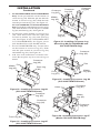
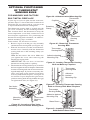
1. Place the front log (#1) on the grate fingers. Make
sure the front log rests firmly between the grate
fingers and the grate base (see Figure 19).
2. Place the base of the middle log (#2) in the
U-shaped slots of the grate base. The cutout
on the right of the middle log should fit over
the burner (see Figure 20). Make sure the front
of the middle log is resting on the tabs of the
grate base.
3. Locate pins on the bottom of back log (#3).
Slide these pins into the holes in the grate base
behind the burner (see Figure 21).
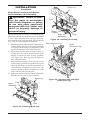
4. Locate holes on the bottom of crossover
log (#4). Slide front hole onto the left pin
(CCL3924PTA/NTA or CCL3930PTB/
NTB) or middle pin (CCL3018PA/NA or
CCL3018PTA/NTA) on the middle log (#2)
and the pin on the back log (#3). See Figure
22, page 17, for placement.
INSTALLATION
Continued
Figure 20 - Installing Middle Log #2
(CCL3930PTB/NTB Shown)
Figure 21 - Installing Rear Log #3
(CCL3930PTB/NTB Shown)
Middle
Log (#2)
Tab
Burner
U-Shaped Slot
Hole in
Grate Base
Pins
Burner
Rear
Log (#3)
Figure 19 - Installing Front Log #1
(CCL3930PTB/NTB Shown)
Front
Log (#1)
Grate
Fingers
Grate
Base

www.desatech.com
113097-01D 17
INSTALLATION
Continued
Figure 22 - Installing Crossover Log #4
(CCL3930PTB/NTB Shown)
Middle
Log (#2)
Back Log
(#3)
Pins
Crossover
Log (#4)
5. For CCL3924PTA/NTA and CCL3930PTB/NTB
Only: Locate pin and hole on the bottom of
crossover log (#5). Slide the pin into the hole
located in crossover log (#4). Slide the hole
onto the pin on front log (#1). See Figure 23.
For CCL3018PA/NA and CCL3018PTA/NTA
Only:
Locate holes on the bottom of crossover log
(#5). Slide the holes over the left pins on middle
log (#2) and front log (#1). See Figure 24.
6. Locate holes on the bottom of crossover log
(#6). Slide these holes onto the right pins
located in middle log (#2) and front log
(#1). See Figure 25 for CCL3924PTA/NTA
or CCL3930PTB/NTB. See Figure 24 for
CCL3018PA/NA or CCL3018PTA/NTA.
7. For CCL3930PTB/NTB only: Locate holes
on the bottom of crossover log (#7). Slide
onto the pins located in crossover log (#6)
and middle log (#2). See Figure 26.
8. Add lava rock around base of heater if de
-
sired. Do not place any lava rock on logs or
burner.
Figure 23 - Installing Crossover Log #5
(CCL3930PTB/NTB Shown)
Crossover
Log (#4)
Front Log (#1)
Crossover
Log (#5)
Crossover
Log (#4)
Front
Log (#1)
Figure 24 - Installing Crossover Log
#5 and Log #6 (CCL3018PA/NA and
CCL3018PTA/NTA Only)
Crossover
Log (#5)
Middle
Log (#2)
Crossover
Log (#6)
7
6
Figure 25 - Installing Crossover Log #6
(CCL3930PTB/NTB Shown)
Figure 26 - Installing Crossover Log #7
(Model CCL3930PTB/NTB Only)
Pins
Middle
Log (#2)Front
Log (#1)
Middle
Log (#2)
Crossover
Log (#6)
Holes
Pins
Crossover
Log (#6)
Crossover
Log (#7)

www.desatech.com
113097-01D
18
INSTALLATION
Continued
Single Burner Seasonal Oak Models
CRL2718PA/NA, CRL3124PA/NA
WARNING: Failure to posi-
tion the parts in accordance
with these diagrams or failure
to use only parts specifically
approved with this heater may
result in property damage or
personal injury.
The Seasonal Oak Log Set is a reversible log set.
This means that the two bottom logs may be turned
to face either direction. The top logs, however,
must remain in the same position. Do not modify
logs. Only use logs supplied with heater.
1. Place the back log onto the back of the base as
-
sembly. Make sure log sits forward against the
two posts in front of log (see Figure 27). This
log may be turned to face either direction.
2. Place front log onto grate on front of base as
-
sembly. The log will fit down between grate
fingers and posts on front of base assembly
(see Figure 28). This log may be turned to
face either direction.
3. Place the left and right crossover logs on top
of the back log and front log. Make sure pins
on front and back are inserted into holes on
crossover logs (see Figure 29). Crossover logs
must be placed as shown in Figure 29 or the
holes will not seat onto the pins.
4. Add lava rock around base of heater if desired.
Do not put lava rock on logs or burner.
Figure 27 - Installing Back Log
Figure 28 - Installing Front Log
Front Log
Grate
Fingers
Figure 29 - Installing Left and Right
Crossover Logs
Back Log
Post
Post
Post
Base
Assembly
Post
Base
Assembly
Left Crossover Log
Right
Crossover Log

www.desatech.com
113097-01D 19
OPERATING HEATER
MANUALLY-CONTROLLED
MODELS
FOR YOUR SAFETY
READ BEFORE LIGHTING
WARNING: If you do not fol-
low these instructions exactly,
a fire or explosion may result
causing property damage, per
-
sonal injury or loss of life.
A. This appliance has a pilot which must be
lighted by hand. When lighting the pilot,
follow these instructions exactly.
B. BEFORE LIGHTING smell all around the
appliance area for gas. Be sure to smell next
to the floor because some gas is heavier than
air and will settle on the floor.
WHAT TO DO IF YOU SMELL GAS
• Do not try to light any appliance.
• Do not touch any electric switch; do not
use any phone in your building.
• Immediately call your gas supplier
from a neighborʼs phone. Follow the
gas supplierʼs instructions.
• If you cannot reach your gas supplier,
call the fire department.
C. Use only your hand to push in or turn the
gas control knob. Never use tools. If the
knob will not push in or turn by hand, donʼt
try to repair it, call a qualified service tech
-
nician or gas supplier. Force or attempted
repair may result in a fire or explosion.
D. Do not use this appliance if any part has
been under water. Immediately call a
qualified service technician to inspect the
appliance and to replace any part of the
control system and any gas control which
has been under water.
LIGHTING
INSTRUCTIONS
WARNING
• If fireplace has glass doors,
never operate this heater with
glass doors closed. If you op-
erate heater with doors closed,
heat buildup inside fireplace
will cause glass to burst. Make
sure there are no obstructions
across openings of fireplace.
• You must operate this heater
with a fireplace screen in
place. Make sure fireplace
screen is closed before run-
ning heater.
NOTICE: During initial operation
of new heater, burning logs will
give off a paper-burning smell.
Orange flame will also be pres
-
ent. Open damper or window to
vent smell. This will only last a
few hours.
Note: Home owners generally prefer to op-
erate their heater with the chimney damper
closed. This will put all the heat into the room.
However, there may be times you will desire
the full flames of the HI heat setting but will
find the heat output excessive. You can open
the chimney damper (if you have one) fully or
partially to release some of the heat.
WARNING: Damper handle
will be hot if heater has been
running.
1. STOP! Read the safety information in
column 1.
2. Make sure equipment shutoff valve is fully
open.
3. Press in and turn control knob clockwise
to the OFF position.
4. Wait five (5) minutes to clear out any gas.
Then smell for gas, including near the floor.
If you smell gas, STOP! Follow “B” in the
safety information, column 1. If you donʼt
smell gas, go to the next step.

www.desatech.com
113097-01D
20
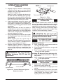
5. Slightly depress and turn control knob
counterclockwise
to the PILOT
position. Press in control knob for five (5)
seconds (see Figure 30).
Note: You may be running this heater for
the first time after hooking up to gas sup-
ply. If so, the control knob may need to be
pressed in for 30 seconds or more. This will
allow air to bleed from the gas system.
6. With control knob pressed in, press and
release ignitor button. This will light pilot.
The pilot is attached to the burner. If
needed, keep pressing ignitor button until
pilot lights.
Note: If pilot does not stay lit, contact a
qualified service person or gas supplier for
repairs. Until repairs are made, light pilot
with match. To light pilot with match, see
Manual Lighting Procedure.
7. Keep control knob pressed in for 30 seconds
after lighting pilot. After 30 seconds, release
control knob.
Note: If pilot goes out, repeat steps 3
through 7. If control knob does not pop out
when released, contact a qualified service
person or gas supplier for repairs.
8. Slightly depress and turn control knob
counterclockwise to desired heat-
ing level. The burner(s) should light. Set
control knob to any heat level between HI
and LO.
WARNING: Do not operate
heater between PILOT and HI
positions.
OPERATING HEATER
Continued
Figure 30 - Control Knob and Ignitor
Button Location
Ignitor Button
Control Knob
Figure 31 - Pilot
Thermocouple
Pilot Burner
Ignitor
Electrode
VARIABLE CONTROL
OPERATION
The variable control valve can be set to any
heat setting and flame height desired, by simply
turning the control knob until that setting is
attained. Even the lowest setting provides re-
alistic, dancing yellow flames. Selecting higher
settings produces greater heat output. This
results in increased heating comfort.
CAUTION: Do not try to ad-
just heating levels by using the
equipment shutoff valve.
TO TURN OFF GAS
TO APPLIANCE
Shutting Off Heater
1. Press in and turn control knob clockwise
to the HI position.
2. Turn control knob clockwise
to the
pilot position.
3. Press in control knob and turn clockwise
to the OFF position.
Shutting Off Burner(s) Only (pilot stays lit)
1. Turn control knob clockwise
to the
HI position.
2. Press in and turn control knob clockwise
to the pilot position.
MANUAL LIGHTING
PROCEDURE
1. Follow steps 1 through 5 under Lighting
Instructions, pages 19 and 20.
2. Depress control knob and light pilot with
match.
3. Keep control knob pressed in for 30 seconds
after lighting pilot. After 30 seconds, release
control knob. Now follow step 8, under
Lighting Instructions, column 1.
Page is loading ...
Page is loading ...
Page is loading ...
Page is loading ...
Page is loading ...
Page is loading ...
Page is loading ...
Page is loading ...
Page is loading ...
Page is loading ...
Page is loading ...
Page is loading ...
Page is loading ...
Page is loading ...
Page is loading ...
Page is loading ...
Page is loading ...
Page is loading ...
Page is loading ...
Page is loading ...
-
 1
1
-
 2
2
-
 3
3
-
 4
4
-
 5
5
-
 6
6
-
 7
7
-
 8
8
-
 9
9
-
 10
10
-
 11
11
-
 12
12
-
 13
13
-
 14
14
-
 15
15
-
 16
16
-
 17
17
-
 18
18
-
 19
19
-
 20
20
-
 21
21
-
 22
22
-
 23
23
-
 24
24
-
 25
25
-
 26
26
-
 27
27
-
 28
28
-
 29
29
-
 30
30
-
 31
31
-
 32
32
-
 33
33
-
 34
34
-
 35
35
-
 36
36
-
 37
37
-
 38
38
-
 39
39
-
 40
40


Desa Tech CCL3018PTA/NTA, CCL3924PTA/NTA, CCL3930PTB/NTB User manual
- Category
- Fireplaces
- Type
- User manual
Ask a question and I''ll find the answer in the document
Finding information in a document is now easier with AI
Related papers
-
FMI VGL18NRA, VGL18PRA, VGL24NRA, VGL24PRA, VGL30NRA, VGL30PRA User manual
-
FMI VF-24P-EMU User manual
-
Desa Tech RLP30A Owner's manual
-
FMI CRL2718PA User manual
-
-
FMI MPF24VNA User manual
-
-
-
-
Other documents
-
Emberglow AEVF18FALP User manual
-
 Spark Modern Fires 59 4ft Installation guide
-
 Spark Modern Fires 53 3ft Original Installation guide
-
 Spark MODERN 59N Owner's Operation And Installation Manual
-
Desa Water Heater 24", 30" User manual
-
 Spark FIRE RIBBON 53 FR-N Owner's Operation And Installation Manual
-
 Spark Modern Fires FIRE RIBBON 53 FR-N Owner's Operation And Installation Manual
-
-
 Spark Modern Fires 57 3ft Installation guide
-
Kingsman Fireplaces GLVF24 User manual


