Page is loading ...

Ameritron SRS-1001 Remote Sensor Add-on Kit Installation Manual
1
Ameritron Remote Sensor Add-on Kit for HI-Q Antennas
Installation Manual
INTRODUCTION
Installation of this simple kit on your screwdriver antenna will allow you to enjoy the
convenience of quickly and accurately returning to antenna settings, when used with the
Ameritron SDC-100 Screwdriver Antenna Digital Controller with Counter.
The Hi-Q screwdriver antenna does not have a magnetic switch installed from the factory. In
order for the Digital Controller to function, the screw driver antenna must have a magnet and a
magnetic switch installed.
Follow the instructions in this manual. Install the magnetic switch onto the antenna. Connect the
sensor wires from the antenna to the digital controller.
PARTS INVENTORY
1 – Surface mounts magnetic contact (switch)
2 – Heavy duty cable straps
2 – lengths of switch wire, one brown, one white
HI-Q 4/80 RT INSTALLATION
(1) From the base of the antenna, locate the hex screws. Above the hex screws will be some
6-32 silver screws. These screws secure the motor inside of the antenna. Measure 2 ½
inches up from the silver screws. This is where the magnet should be located inside the
antenna. Make a mark at this point with tape or similar.
TEMPORARY WIRING AND TESTING
(2) Connect the yellow wire from the Ameritron SDC-100 controller directly to the red wire
from the antenna motor.
(3) Connect the green wire from the Ameritron SDC-100 controller to the wire from the
motor. Wrap the connections with electrical tape or other suitable insulating material.
(4) Connect the Ameritron SDC-100 red (+) and black (-) wires to a 12 VDC source.
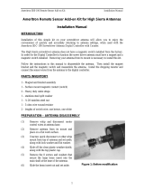
(1) Temporarily secure the switc
h
(Fig.3) to the outside of the
antenna with a piece of tape;
center the switch over the mar
k
corresponding to the position o
f
the magnet.

Ameritron SRS-1001 Remote Sensor Add-on Kit Installation Manual
2
(5) Connect a continuity tester across the two terminals of the switch. Since the switch is
normally “closed,” the continuity tester may indicate a closed circuit at this time,
depending on the position of the magnet relative to the switch.
(6) Apply 12 VDC to the Ameritron SDC-100 and turn the Ameritron SDC-100 on. Press
UP or DOWN to turn the antenna motor; you will hear the motor run.
(7) As the motor turns you should be able to observe the continuity tester going “on” and
“off” as the switch alternates between open and closed. If you are not seeing this result,
adjust the position of the switch on the shaft up or down very small amounts until the
switch shows “on” and “off” on the continuity tester. The correct alignment of the
magnet and switch is critical for proper operation.
(8) Remove the tape from the switch and secure it in place with the plastic cable straps,
making sure to keep the switch in exactly the same position on the main shaft.
(9) Remove the continuity tester.
(10) Temporarily connect the sensor wires (brown and white) from the Ameritron SRS-1001
to the switch terminals (the polarity does not matter). Now, when you activate the motor,
the on/off analog signal from the switch will cause the LED counter in the Ameritron
SDC-100 to “count.”
(11) Proceed with calibration instructions in the Ameritron SDC-100 manual..
TECHNICAL ASSISTANCE
If you have any problem with this unit first check the appropriate section of this manual. If the
manual does not reference your problem or your problem is not solved by reading the manual,
you may call Ameritron at 662-323-8211. You will be best helped if you have your unit, manual
and all information on your station handy so you can answer any questions the technicians may
ask.
You can also send questions by mail to Ameritron, 116 Willow Road, Starkville, MS 39759; by
Facsimile (FAX) to 662-323-6551. Send a complete description of your problem, an explanation
of exactly how you are using your unit, and a complete description of your station.
/


