Page is loading ...

Page 1
INSTALLATION INSTRUCTIONS FOR GAS MANIFOLD PRESSURE TEST KIT (21U27; 622686-01)
USED WITH LS25 / UHSC SEPARATED COMBUSTION UNIT HEATERS
508103-01
11/2020 GAS MANIFOLD
PRESSURE TEST KIT
PACKAGED UNITS KITS
©2020
WARNING
Improper installation, adjustment, alteration, ser
vice or maintenance can cause property damage,
personal injury or loss of life. Installation and ser
vice must be performed by a licensed professional
installer (or equivalent), service agency or the gas
supplier.
CAUTION
As with any mechanical equipment, contact with
sharp sheet metal edges can result in personal in
jury. Take care while handling this equipment and
wear gloves and protective clothing.
CAUTION
Electrostatic discharge can affect
electronic components. Take precau
tions to neutralize electrostatic charge
by touching your hand and tools to
metal prior to handling the control.
Shipping & Packing List
Package 1 of 1 contains the following:
1 - Tubing assembly (tee with long and short tubing)
1 - Round tubing (22” length)
1 - White Rodgers adapter kit (36G only)
1 - Barbed fitting (36H only)
Application
Kit (21U27) provides tubing and fittings needed to
measure total manifold pressure for LS25 / UHSC
Separate Combustion Unit Heaters. To correctly measure
total manifold pressure on these models, the pressure at
the positive gas manifold and the negative burner box
must be considered.
NOTE- Total manifold pressure is the sum of the positive
“+” and negative “-” sides of the manifold pressure.
Gas Manifold Check
Gas Manifold Check - White Rodgers 36G Series
Single-Stage Gas Valve
A manifold pressure post located on the gas valve
provides access to the manifold pressure. See figure 1,
figure 2, and the following steps.
1- Use the adapter kit Allen wrench to back out the 3/32”
hex screw from the gas manifold pressure post one
turn.
2- Connect one end of the adapter kit tubing to the
manifold pressure port. Connect the other end of the
adapter kit tubing to the 5/16” end of the adapter kit
reducer.
3- Connect one end of the 22” round tubing to the ¼”
side of the adapter kit reducer. Connect the other end
of the 22” round tubing to the “+” positive side of the
measuring device.
4- Carefully remove the factory-installed tubing from the
gas valve vent barb. Connect the factory-installed
tubing to the open end of the tubing assembly tee.
5- Connect the tubing assembly short tubing leg to the
gas valve vent barb. Connect the long tubing leg to
negative “-” side of measuring device.
6- Start heat and let run for 5 minutes to allow for steady
state conditions.
7- After allowing unit to stabilize for 5 minutes, record
total manifold pressure. Compare manifold pressure
to unit rating plate or installation instruction high
altitude tables as applicable.
8- If necessary, make adjustments. Figure 1 shows
adjustment screw location. Access adjustment
screw(s) by removing brass cap screw. Reinstall
brass cap screw(s) after adjustments are completed.
9- When accurate reading(s) and adjustment(s) are
made, shut unit off and remove measuring device.
10- Close the gas manifold pressure port 3/32” hex screw
securely.
11- Reconnect the factory tubing to the gas valve vent
barb.
12- Start unit and perform leak check. Seal leaks if found.
FIGURE 1
WHITE RODGERS 36G GAS VALVE
Single-Stage
GAS VALVE SWITCH SHOWN IN OFF POSITION.
MANIFOLD
PRESSURE
ADJUSTMENT
SCREW
INLET
PRESSURE
PORT
MANIFOLD
PRESSURE
OUTLET

Page 2
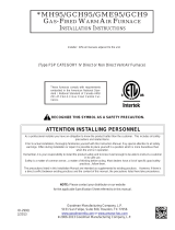
FIGURE 2
WHITE-RODGERS 36G GAS VALVE
Manifold Pressure
Post
5/16” Round Hose
(in adapter kit)
Reducer
Fitting
(in adapter kit)
22”
Tubing
Measuring Device
(Manometer)
Vent Hose Barb
Tubing
Assembly
Tubing Removed
from Gas Valve Vent
Hose Barb
Gas Manifold Check - White Rodgers 36H Series
Two-Stage Gas Valve
A ⅛” NPT tapped plug located on the gas valve provides
access to the manifold pressure outlet. See figure 3,
figure 4, and the following steps.
1- Remove and retain the gas manifold pressure outlet
⅛” NPT plug.
2- Install the threaded end of the barbed fitting into the
⅛” NPT manifold pressure outlet.
3- Connect one end of the 22” round tubing to the
barbed fitting. Connect the other end of the 22” round
tubing to the “+” positive side of the measuring
device.
4- Carefully remove the factory-installed tubing from the
gas valve vent barb. Connect the factory-installed
tubing to the open end of the tubing assembly tee.
5- Connect the tubing assembly short tubing leg to the
gas valve vent barb. Connect the long tubing leg to
negative “-” side of measuring device.
FIGURE 3
WHITE RODGERS 36H SERIES GAS VALVE
Two−Stage
GAS VALVE SWITCH SHOWN IN OFF POSITION
MANIFOLD
PRESSURE
ADJUSTMENT
SCREWS
INLET
PRESSURE
PORT
MANIFOLD
PRESSURE
OUTLET

Page 3
6- Start unit on high heat and let run for 5 minutes to
allow for steady state conditions.
7- After allowing unit to stabilize for 5 minutes, record
total manifold pressure. Compare manifold pressure
to unit rating plate or installation instruction high
altitude tables as applicable.
8- If necessary, make adjustments. Figure 3 shows
adjustment screw locations. Access adjustment
screw(s) by removing brass cap screw. Reinstall
brass cap screw(s) after adjustments are completed.
9- Repeat steps 6, 7, and 8 on lower input.
10- When accurate reading(s) and adjustment(s) are
made, shut unit off and remove measuring device.
11- Reinstall the ⅛” NPT plug retained in step 1.
12- Reconnect the factory tubing to the gas valve vent
barb.
13- Start unit and perform leak check. Seal leaks if found.
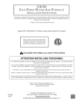
FIGURE 4
WHITE-RODGERS 36H GAS VALVE
Manifold
Pressure Outlet
- ⅛” NPT Plug
22”
Tubing
Measuring Device
(Manometer)
Vent Hose
Barb
Tubing
Assembly
Tubing Removed
from Gas Valve
Vent Hose Barb
/