Datalogic CBX series Owner's manual

Type
Owner's manual

This manual is also suitable for

Datalogic CBX series is a versatile accessory designed to simplify system connections for installation and device replacement of Datalogic data collection devices. It acts as a central hub, facilitating connections for power, presence sensors, triggers, encoders, and I/O devices. The CBX series provides a convenient way to monitor data and configure devices through its auxiliary serial interface. With its flexible mounting options, the CBX series can be easily integrated into various setups, including DIN rails and Bosch Frames.

Datalogic CBX series is a versatile accessory designed to simplify system connections for installation and device replacement of Datalogic data collection devices. It acts as a central hub, facilitating connections for power, presence sensors, triggers, encoders, and I/O devices. The CBX series provides a convenient way to monitor data and configure devices through its auxiliary serial interface. With its flexible mounting options, the CBX series can be easily integrated into various setups, including DIN rails and Bosch Frames.

CBX510
Installation Manual
The CBX510 is a connection box which can be used as an accessory to facilitate
system connections for installation and device replacement of several Datalogic
family data collecting devices.
System cabling is made through spring clamp terminal blocks inside the CBX510
while the data collecting device is connected to the CBX510 through a 25-pin
connector on the housing.
A 9-pin connector placed inside the CBX510 facilitates connection between an
external PC and the auxiliary serial interface of the data collecting device for data
monitoring.
CBX510 can also house an accessory Backup and Restore Module to make
system maintenance extremely quick and easy.
GENERAL VIEW
CBX510
Figure A
Figure B
SAFETY PRECAUTIONS
ATTENTION: READ THIS INFORMATION BEFORE INSTALLING THE
PRODUCT
This product is intended to be installed by Qualified Personnel only.
The power supplied to the CBX510 from the data collecting device
must be between 10 and 30 Vdc only, typically it is 24 Vdc.
CAUTION: CBX510 only accepts power directly from the data
collecting device connected through the 25-pin connector. This
allows passing power to connected accessories such as
Encoder/Tach and Presence Sensor/Trigger from SC5000 or
DS8110/DX8210 scanners powered directly. See the relative data
collecting device Reference Manual for details.
CAUTION: +V and -V signals must not be used as power
supply inputs to the CBX510 nor to the data collecting device.
NOTE: To avoid electromagnetic interference:
- Connect CBX510 Protection Earth (Earth) to a good earth
ground.
- Connect the data collecting device chassis to earth ground
through the jumper, (default setting, see Figure 5).
- Connect the Cable Shields to the Shield spring clamp
connectors.
POWER CONSUMPTION NOTE
Total power consumption is given by adding the CBX510 power consumption to
that of all the devices powered through the CBX510 (BM100 Backup Module,
Trigger, Encoder/Tach, I/O). Refer to the example below and the manual of the
connected devices for details about minimum/maximum supply voltage and
power consumption.
The following example shows current consumption for the most common system
devices being powered through the CBX510.
Example:
Data Collecting device = DS8110: sourcing 24 Vdc power
For CBX510, a typical power consumption of about 360 mA @ 24
Vdc includes the following devices:
LEDs (all on) Output 1 (sourcing 40 mA max continuous current)
Trigger Output 2 (sourcing 40 mA max continuous current)
Encoder BM100
NOTE: CBX510 contains a resettable overcurrent protection
device which in case of component failure (i.e. short-circuit),
prevents current exceeding 0.7 A to be drawn from its power
source (data collecting device).
SUPPORTED DATA COLLECTING/POWER SOURCING DEVICES
The CBX510 can be directly connected to the following data collecting devices
through the 25-pin connector illustrated in Figure A, 5.
Linear Scanners 2D Readers
DS2100N DS2400N DS4800 DS5100 All Matrix x10 family
DS6x00 DX6400 DS8100A DX8200A All Matrix x10N family
OPENING THE CBX510
To install the CBX510 or during normal maintenance, it is necessary to open it by
unscrewing the four cover screws:
CAUTION: The CBX510 must be disconnected from the power
supply during this operation (25-pin connector disconnected - Figure
A, 5).
MECHANICAL INSTALLATION
CBX510 can be mounted to various wooden or plastic surfaces using the two self-
threading screws (3.9 x 45 mm) and washers provided in the package.
Mounting to other surfaces such as concrete walls or metallic panels requires
user-supplied parts (screws, screw anchors, nuts, etc). A mounting template is
included in the package to facilitate hole drilling alignment.
The following accessories are available for mounting CBX510 to a DIN rail using
BA100 (93ACC1821), a Bosch Frame using BA200 (93ACC1822).
The diagram below gives the overall dimensions of the CBX510 and shows the
two mounting through-holes.
Figure 1 - Overall Dimensions
ACCESSORIES
The following accessories are available on request for the CBX510:
Name Description Part Number
Memory
BM100 Backup Module 93ACC1808
Mounting
BA100 DIN Rail Mounting Kit 93ACC1821
BA200 Bosch Frame Mounting Kit 93ACC1822
Connectors
BA300 M12 3PF Service Connector (Aux port) 93ACC1877
BA500 M12 4PF Trigger Connector 93ACC1854
BA900 Two Cable Compression Conn. Panel 93ACC1847
Cables
CAB-DS01-S I/O Cable M12-17-pin to 25-pin D-sub 1m 93A050058
CAB-DS03-S I/O Cable M12-17-pin to 25-pin D-sub 3m 93A050059
CAB-DS05-S I/O Cable M12-17-pin to 25-pin D-sub 5m 93A050060
CAB-SC5000 Cable SC5000 to CBX510 1m 93A050071
LAYOUTS
The following figures show typical layouts.
Figure 2 – Standalone Layout
Figure 3 – Master-Slave Layout
After making system cabling, connect a compatible device to the CBX510’s 25-
pin Device Connector (Figure A, 5) through a proper cable. Power on the
compatible device. The CBX510 Power LED turns on (blue) when the power
connection has the correct polarity. In case of wrong polarity, no power is passed
to the CBX510 and the Power LED remains off.
In typical layouts, the data collecting devices (Master or Standalone) are
connected in an Ethernet network to a Host through an Ethernet switch.
The Master or Standalone device is also connected to the CBX510 where it
receives Presence Sensor (Trigger) and Encoder signals. Output devices
connected to the CBX510 can be driven by the device.
Optionally, connections to a Serial Host can be made through the CBX510 using
either the Main or Aux Serial Interfaces.
After system functioning has been verified, close the CBX510 using the four
cover screws (Figure A, 2).
SYSTEM WIRING
The connection and wiring procedure for CBX510 is described as follows:
1) Verify that the CBX510 25-pin connector is free (no connection).
2) Open the CBX510 by unscrewing the four cover screws.
3) Unscrew the compression connectors and pass all the system cables
through them into the CBX510 housing.
4) To connect the input/output signals:
Prepare the individual wires of the system cables by stripping the
insulation back approximately 1 cm.
Using a device such as a small screwdriver, push down on the internal
lever directly above the clamp (circular hole) (see Figure 4).
Insert the wire into the clamp (circular hole) and release the internal
lever.
The wire will now be held in the spring clamp.
5) Tighten the compression connector nuts so that the internal glands seal
around the cables.
Figure 4 - System Cable Connections
Flexible stranded wire should be used and must meet the following
specifications.
All positions: 24 - 16 AWG 0.2 - 1.5 mm²
The CBX510 spring clamp connector pinouts are indicated in the Pinout table.
Indicator LEDs
Cover Screws (4)
Compression Connectors
1
2
4
25-pin Device Connector
A
ccessory Mounting Panel
5
3
Mounting Holes (2)
Backup Module Connector
Indicator LEDs
1
2
3
A
uxiliary Port Connecto
r
Spring Clamp Terminal Blocks
Device Chassis Grounding Selector
4
5
6
1
6
4
3 3
2
5
2
1
5 4
3
Mounting
Holes
mm
[in]
Data Collecting Devices
CBX510
Power
ENC, PS, I/O
Ethernet EBC
CAB-DS0x-S
Slaves
Main and
A
ux Serial Interfaces
for serial Host connections o
r
data monitoring
Master
to Host
(ETH-1)
to configuration PC (ETH-2)
CBX510
ENC, PS, I/O
CAB-DS0x-S
Main and Aux Serial Interfaces
for serial Host connections o
r
data monitoring
Power
to Host (ETH-1)
to config PC (ETH-2)
Refer to the data collecting device Installation Manual for signal details.
Pinouts
Group Name Function
Grounding Earth Protection Earth Ground (PE)
I/O Power +V I/O Power Source
-V I/O Power Reference
Trigger/PS
Input
I1A External Trigger A (polarity insensitive)
I1B External Trigger B (polarity insensitive)
Encoder/Tach
Input
ENA Encoder A (polarity insensitive)
ENB Encoder B (polarity insensitive)
Generic Input I3A Input 3A (polarity insensitive)
I3B Input 3B (polarity insensitive)
Generic
Outputs
O1+ Output 1 +
O1- Output 1 -
O2+ Output 2 +
O2- Output 2 -
Other I/O
O3+ Output 3 + (only for SC5000)
O3- Output 3 - (only for SC5000)
IO4+ Programmable Input/Output 4+ (only for SC5000)
IO4- Programmable Input/Output 4- (only for SC5000)
Auxiliary
Interface
TX Auxiliary Interface TX
RX Auxiliary Interface RX
SGND Auxiliary Interface Reference
Shielding Shield Cable Shields (internally connected to PE)
RS232 RS422/485 FD
Main Interface
TX TX+
RTS TX-
RX *RX+
CTS *RX-
SGND** SGND**
* Do not leave floating, see Data Collecting Device Reference Manual for
connection details.
** When connected to SC5000 the Main SGND is opto-isolated.
SHIELD TO PROTECTION EARTH
All I/O device and Serial Host Interface cable shields can be connected to Earth
ground (PE) by inserting them into any one of the CBX510 Shield clamp
connectors.
CHASSIS GROUNDING JUMPER SETTINGS
The data collecting device chassis grounding method can be selected by
positioning a jumper (see Figure 5 and Figure B, 6). In this way the data
collecting device chassis can be connected to earth ground (only if pin Earth is
connected to a good earth ground). For DS8110 and DX8210, the chassis is
internally connected to the scanner GND.
Figure 5 – Chassis Grounding
MAIN AND AUXILIARY SERIAL INTERFACES
Connections to a Serial Host (if permanent), should be made through the
CBX510 using either the Main or Aux Serial Interface internal spring clamp
connectors.
Instead, for data monitoring, the data collecting device auxiliary serial interface
can be connected temporarily to a portable PC through the internal CBX510
9-pin connector. This connection can be made to a PC using a straight through
cable or a USB-RS232 converter.
See the data collecting device Installation Manual and Help On Line for more
details.
The details of the connector pins are indicated in the following table:
CBX510 9-pin D-Sub Female Connector Pinout
Pin Name Function 5 1
69
2 TX Auxiliary RS232
3 RX Auxiliary RS232
5 SGND Auxiliary Reference Ground
1, 4, 6, 7, 8, 9 N.C.
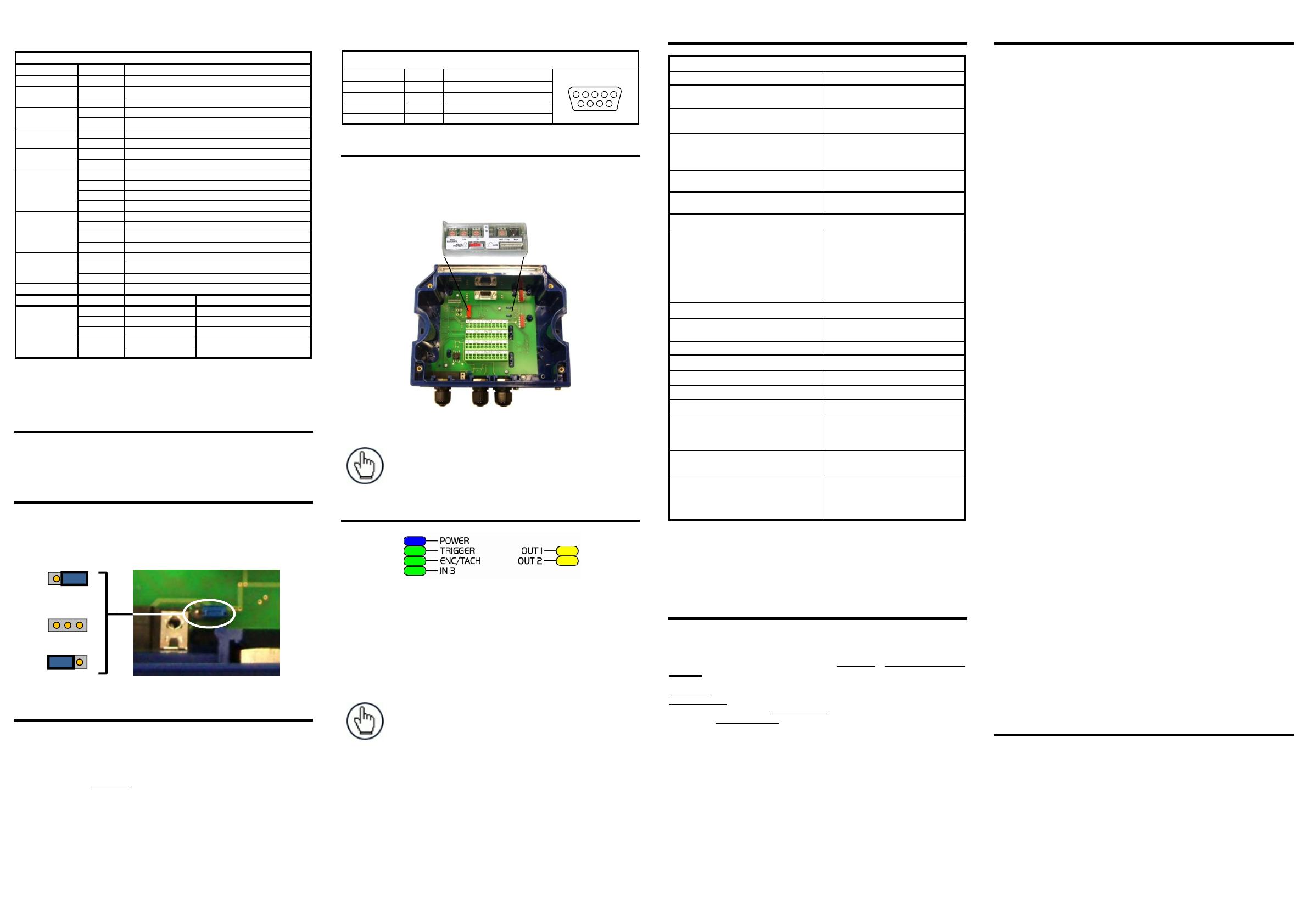
BM100 BACKUP AND RESTORE MODULE (ACCESSORY)
The BM100 Backup and Restore Module (separate accessory) provides
configuration parameter backup. It can easily be installed by aligning it over its
corresponding connector in the CBX510 and pushing down until correctly seated.
When closed, the plastic support inside the CBX510 cover holds the module in
place. For further details see the BM100 manual.
Figure 6 – BM100 Accessory Mounting
NOTE: All-in one models come with BM100 pre-installed.
INDICATOR LEDS
Figure 7 – Indicator LEDs
There are six Indicator LEDs which signal power and I/O activity and are visible
from the CBX510 outside cover (Figure A, 1).
The Power LED is blue when power is correctly applied to the CBX510.
In case of wrong polarity, no power is passed to the CBX510 and the Power LED
remains off. In this case the connected data collecting device and optional
Backup Module are protected.
NOTE: All the external I/O devices powered through CBX510
(connected to +V/-V), are protected from polarity inversion.
The remaining five LEDs signal activity on the relative I/O lines. Their meaning
depends on the software configuration of the connected data collecting device.
TECHNICAL FEATURES
ELECTRICAL FEATURES
Supply Voltage 10 to 30 Vdc*
Consumption (see Power Consumption
Note on opposite page)
0.5 A max.
Inputs 1, 2 and 3
Non opto-isolated polarity insensitive
30 Vdc max; 12 mA max
Outputs 1 and 2
Opto-isolated polarity sensitive
30 Vdc max; 40 mA max continuous
130 mA max pulsed
Output 3
Non opto-isolated Pass through
Input / Output 4
Non opto-isolated Pass through
USER INTERFACE
LED Indicators Power On (blue)
TRIGGER (green)
ENC/TACH (green)
IN3 (green)
OUT1 (yellow)
OUT2 (yellow)
PHYSICAL FEATURES
Mechanical Dimensions 193 x 180 x 71 mm
(7.6 x 7.1 x 2.8 in.)
Weight about 800 g. (28.25 oz.)
ENVIRONMENTAL FEATURES
Operating Temperature 0° to 50 C (+32° to 122 °F)
Storage Temperature -20° to 70 C (-4° to 158 °F)
Humidity max. 90% non condensing
Vibration Resistance 14 mm @ 2 to 10 Hz
EN 60068-2-6
2 hours on each axis
1.5 mm @ 13 to 55 Hz
2 g @ 70 to 200 Hz
Shock Resistance 30 g; 11 ms;
EN 60068-2-27 3 shocks on each axis
Protection Class
EN 60529
IP65
(when compression connectors and
reading device are correctly
connected)
The features given are typical at a 25 C ambient temperature (if not otherwise
indicated).
* for further details about minimum/maximum supply voltage refer to the manual
of the connected reading device, since the minimum supply voltage required
may be >10.
SUPPORT THROUGH THE WEBSITE
Your product Reference Manual including installation procedures is available for
download on our website as well as the configuration program.
Datalogic provides several services as well as technical support through its website.
Log on to www.datalogic.com and click on the SUPPORT > Unattended Scanning
Systems category link. From this page you can select your product model from the
dropdown list which gives you access to:
Downloads including Data Sheets, Manuals, Software & Utilities, and Drawings;
Repair Program for On-Line Return Material Authorizations (RMAs) plus Repair
Center contact information; Service Program containing details about Maintenance
Agreements; Technical Support through email or phone.
COMPLIANCE
This product is intended to be installed by Qualified Personnel only.
Power Supply
This device is intended to be supplied by a UL Listed or CSA Certified Power Unit
with Class 2 or LPS power source, which supplies power directly through the 25-pin
connector.
CE Compliance
CE marking states the compliance of the product with essential requirements listed in
the applicable European directive. Since the directives and applicable standards are
subject to continuous updates, and since Datalogic promptly adopts these updates,
therefore the EU declaration of conformity is a living document. The EU declaration of
conformity is available for competent authorities and customers through Datalogic
commercial reference contacts. Since April 20th, 2016 the main European directives
applicable to Datalogic products require inclusion of an adequate analysis and
assessment of the risk(s). This evaluation was carried out in relation to the applicable
points of the standards listed in the Declaration of Conformity. Datalogic products are
mainly designed for integration purposes into more complex systems. For this reason
it is under the responsibility of the system integrator to do a new risk assessment
regarding the final installation.
Warning: This is a Class A product. In a domestic environment this product may
cause radio interference in which case the user may be required to take adequate
measures.
FCC Compliance
Modifications or changes to this equipment without the expressed written
approval of Datalogic could void the authority to use the equipment.
This device complies with PART 15 of the FCC Rules. Operation is subject to the
following two conditions: (1) This device may not cause harmful interference, and
(2) this device must accept any interference received, including interference
which may cause undesired operation.
This equipment has been tested and found to comply with the limits for a Class A
digital device, pursuant to part 15 of the FCC Rules. These limits are designed to
provide reasonable protection against harmful interference when the equipment
is operated in a commercial environment. This equipment generates, uses, and
can radiate radio frequency energy and, if not installed and used in accordance
with the instruction manual, may cause harmful interference to radio
communications. Operation of this equipment in a residential area is likely to
cause harmful interference in which case the user will be required to correct the
interference at his own expense.
EAC Compliance
Customs Union:
The CU Conformity certification has been achieved; this allows the Product to
bear the Eurasian mark of conformity.
LEGAL NOTICE
© 2014 – 2017 Datalogic S.p.A. and/or its affiliates ALL RIGHTS RESERVED.
Without limiting the rights under copyright, no part of this documentation may be
reproduced, stored in or introduced into a retrieval system, or transmitted in any form
or by any means, or for any purpose, without the express written permission of
Datalogic S.p.A. and/or its affiliates.
Datalogic and the Datalogic logo are registered trademarks of Datalogic S.p.A. in
many countries, including the U.S. and the E.U.
Datalogic shall not be liable for technical or editorial errors or omissions contained
herein, nor for incidental or consequential damages resulting from the use of this
material.
821002652 (Rev. B)
to Earth
(default)
to GND
floating
blue
green
green
yellow
green
yellow
  • Page 1 1
  • Page 2 2

Datalogic CBX series Owner's manual

Type
Owner's manual
This manual is also suitable for

Datalogic CBX series is a versatile accessory designed to simplify system connections for installation and device replacement of Datalogic data collection devices. It acts as a central hub, facilitating connections for power, presence sensors, triggers, encoders, and I/O devices. The CBX series provides a convenient way to monitor data and configure devices through its auxiliary serial interface. With its flexible mounting options, the CBX series can be easily integrated into various setups, including DIN rails and Bosch Frames.

Ask a question and I''ll find the answer in the document

Finding information in a document is now easier with AI