Dometic Optimus 360 Joystick Control System Installation guide
- Type
- Installation guide

Joystick Control System for Engines with Integrated
Electronic Shi and Throttle
Installation Manual — Book 63
[REVISION F-05] Form No. 682114 | ©2020 Dometic Corporation
WARNING
Cancer and Reproductive Harm
www.P65Warnings.ca.gov
EN
OPTIMUS 360 JOYSTICK
CONTROL SYSTEM

ii
EN
All information, illustrations and specifications in this manual are based on
the latest information available at the time of publishing. The illustrations
used in this manual are intended as representative reference views only.
Moreover, because of our continuous product improvement policy, we
may modify information, illustrations and/or specifications to explain and/
or exemplify a product, service or maintenance improvement. We reserve
the right to make any change at any time without notice.
©2020 Dometic
All Rights Reserved. This document, subject matter and all information
herein is the sole, exclusive and confidential property of Dometic and shall
not be disclosed, copied, reproduced or used in whole or in part for any
purpose other than as specifically authorized in writing by Dometic.
is a registered trademark of the American Boat &
Yacht Council (http://www.abycinc.org)
NMEA 2000
®
is a registered trademark of the National Marine
Electronics Association.
Optimus, Optimus 360, SeaStar, and BayStar are all trademarks of Dometic.
California
Proposition 65 Warning
Battery posts, terminals, and related accessories contain
lead and lead compounds, chemicals known to the state
of California to cause cancer and reproductive harm.
Wash hands aer handling.
This book contains:
• instructions required to install and calibrate the Optimus 360 Joystick
Control System for electronic shift and throttle engines.
This document is to be utilized in conjunction with the Optimus Hydraulic EPS
Installation Manual (PID #682158), Optimus Electric EPS Installation Manual
Book 54 (PID #682220), and Book 65 (PID #682170). These books contain
installation, calibration, and purging instructions for the base electronic
steering system, upon which the joystick control system is built.
This book must be delivered to the owner when installation is complete.
Thank you for choosing the Optimus
™
360 Joystick Control System. You
have chosen a state of the art steering system that will provide years of
effortless and trouble free steering performance.
About this Book

iii
EN
Table of Contents
Abbreviations ........................................................................ vi
1 Important Safety Information ............................................... 1-1
1.1 Explanation of symbols .................................................... 1-1
1.2 Safe operation ............................................................... 1-2
1.3 Safety considerations for installers .................................... 1-3
2 System Overview ................................................................. 2-1
2.1 System description ......................................................... 2-1
3 Installation ........................................................................... 3-1
3.1 Important information/Technical Support contact .............. 3-1
3.2 Installation overview ....................................................... 3-1
3.2.1 Part 1: Component installation ............................... 3-2
3.2.2 Part 2: System calibration, purging and setup .......... 3-2
3.3 Installing the Joystick ...................................................... 3-3
3.3.1 Joystick types ....................................................... 3-3
3.4 CAN1 Harness connections ............................................ 3-4
3.5 CAN2 Harness connections ........................................... 3-5
4 System Setup, Purge, and Calibration ................................. 4-1
4.1 Initial system setup ......................................................... 4-1
4.2 Purge and calibrate ....................................................... 4-3
4.3 Engine-specific setup .................................................... 4-3
5 Evinrude .............................................................................. 5-1
5.1 Evinrude and Optimus 360 network interconnection .......... 5-1
5.1.1 Evinrude ETEC G2 with iDock ................................ 5-1
6 Suzuki .................................................................................. 6-1
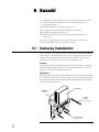
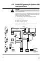
6.1 Gateway installation ....................................................... 6-1
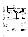
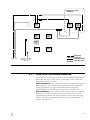
6.2 Suzuki EST gateway and Optimus 360 interconnection ...... 6-2
6.2.1 Suzuki BCM CAN network connection ................... 6-5
6.2.2 Suzuki switch panel harness connection ................. 6-6
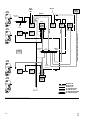
6.2.3 Optimus EST gateway connection ......................... 6-7
6.2.4 Optimus CAN 1 and CAN 2 connections ................ 6 -7
6.2.5 Optimus PCM ignition sensing .............................. 6-7
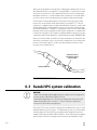
6.3 Suzuki SPC system calibration ......................................... 6-8
7 Yamaha ................................................................................ 7-1
7.1 Yamaha DEC ................................................................. 7-1
7.1.1 Yamaha DEC remote control connections ................ 7-1
7.1.2 EST gateway installation for Yamaha DEC ................. 7-5
7.1.3 Yamaha DEC EST gateway and Optimus 360
connection .......................................................... 7-7

iv
EN
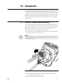
7.2 Yamaha EX .................................................................. 7-13
7.2.1 Yamaha EX remote control connections ................. 7-13
7.2.2 EST gateway installation for Yamaha EX .................. 7-14
7.2.3 Yamaha EX EST gateway and Optimus 360
connection ........................................................ 7-15
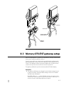
7.3 Yamaha EST gateway setup ........................................... 7-17
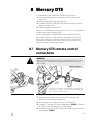
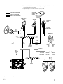
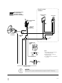
8 Mercury DTS .........................................................................8-1
8.1 Mercury DTS remote control connections ......................... 8-1
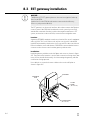
8.2 EST gateway installation ................................................. 8-4
8.3 Mercury DTS/EST gateway setup .................................... 8-5
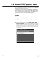
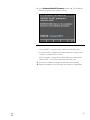
9 Honda IST ............................................................................ 9-1
9.1 Honda IST remote control connections ............................. 9-1
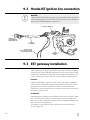
9.2 Honda IST ignition line connection .................................. 9-4
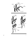
9.3 EST gateway installation ................................................. 9-4
9.4 Honda IST/EST gateway setup ........................................ 9-6
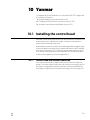
10 Yanmar .............................................................................. 10-1
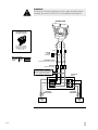
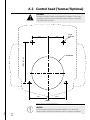
10.1 Installing the control head ............................................. 10-1
10.1.1 Control head trim switch connection ..................... 10-1
10.2 Yanmar and Optimus 360 CAN2 interconnection............. 10-3
10.3 Control head setup ...................................................... 10-6
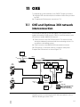
11 OXE ..................................................................................... 11-1
11.1 OXE and Optimus 360 network interconnection ............... 11-1
12 Post-Installation Warranty Checklist ...................................12-1
13 Updating Firmware............................................................. 12-1
14 Warranty ............................................................................. 14-1
14.1 Statement of limited warranty ......................................... 14-1
14.2 Return goods procedure ................................................ 14-1
14.3 Technical support ......................................................... 14-1
14.4 Authorised service centers & distributors ......................... 14-1

v
EN
Appendix A – Mounting Templates ............................................ A-1
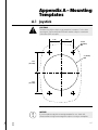
A.1 Joystick ......................................................................... A-1
A.2 Control head (Yanmar/Optimus) ..................................... A-3
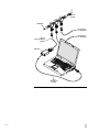
Appendix B – Setup and Tuning with Datalink ........................... B-1
B.1 Using Datalink ............................................................... B-1
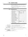
B.2 System setup ................................................................ B-3
B.2.1 System parameters ............................................. B-3
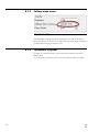
B.2.2 Settings menu access ......................................... B-4
B.2.3 Cycle power to system ........................................ B-4
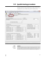
B.3 Joystick tuning procedure ............................................... B-5
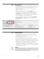
B.3.1 General notes .................................................... B-6
B.3.2 Before you start .................................................. B-6
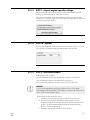
B.3.3 STEP 1 – Import engine-specific settings ................ B-7
B.3.4 STEP 1a – System ................................................ B-7
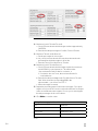
B.3.5 STEP 2 – Set throttle limits .................................... B-7
B.3.6 STEP 3 – Run throttle wizards ............................... B-9
B.3.7 STEP 4 – Set forward heading correction .............. B-10
B.3.8 STEP 5 – Balance rotation power .......................... B-11
B.3.9 STEP 6 – Set sideways rudder angle ..................... B-12
B.3.10 STEP 7 – Balance sideways engine power ............. B-13
B.3.11 STEP 8 – Adjust power levels .............................. B-14
B.3.12 STEP 9 – Sea trial ............................................... B-15
B.3.13 STEP 10 – Saving the joystick tuning file ................ B-15
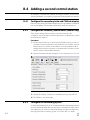
B.4 Adding a second control station .................................... B-16
B.4.1 Configure the secondary helm and
CANtrak display ................................................ B-16
B.4.2 Configure the secondary control head
Yanmar only) ..................................................... B-16
B.4.3 Configure the secondary joystick ........................ B-16
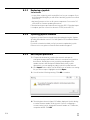
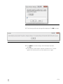
B.5 Importing a joystick tuning file ....................................... B-17
B.5.1 Configuring a second joystick ............................. B-17
B.5.2 Using a template file .......................................... B-17
B.5.3 Replacing a joystick ........................................... B-18
B.5.4 Updating joystick firmware ................................. B-18
B.5.5 Basic import procedure ..................................... B-18
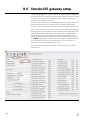
B.6 Yamaha EST gateway setup ........................................... B-20
B.6.1 System ............................................................. B-21
B.6.2 LPS calibration .................................................. B-21

vi
EN
Abbreviations
The following abbreviations are used in this manual:
ABYC American Boat & Yacht Council
AUX Auxiliary
BAT Battery
BCM Boat Control Module (Suzuki)
CAN Controller Area Network
CAN bus Controller Area Network (data) bus. (A harness of
wires that carry digital signals and power between
electronic modules)
CL/CLP Command Link/Command Link Plus (Yamaha)
DC Direct current
DEC Digital Electronic Control (Yamaha)
ECM Engine control module
ENG Engine
EPS Electronic Power Steering
EST Electronic shift and throttle
FT-LB Foot-pounds, a US unit of torque
FWD Forward
GND Ground
HI High
IN-LB Inch-pounds, a US unit of torque
LED Light emitting diode
LO Low
LPS Lever position sensor
MPH Miles per hour
NA Not applicable or Not available
N/C No connection
Nm Newton-meters, a metric measure of torque
NMEA National Marine Electronics Association
NMEA 2000
®
A protocol for digital communication on a CAN Bus
OEM Original equipment manufacturer
PCM Pump control module
REV Reverse
ROT Rotation mode (joystick control)
RPM Revolutions per minute
SIDE Sideways mode (joystick control)
STBD Starboard (right when facing forward)
SW Switch
WOT Wide open throttle
NOTE
Some abbreviations not listed here may be found in their respective sections.

1-1
EN
1 Important Safety
Information
Safe operation of the Optimus™ 360 Joystick Control System depends on
proper installation and maintenance of the system, as well as the operator’s
safe judgment, boating knowledge, and expertise.
The installer and operator must read and understand the safety requirements
in this section before installing or using the steering system. If you have any
questions about safe installation or operation of this system, contact
Dometic Marine. Please don’t guess.
The symbols below are used throughout this publication to alert you to
potential hazards involved with the operation and installation of this product.
Observe these warnings and notices carefully. The safety alerts alone
cannot eliminate hazards; strict compliance with any special instructions
during installation, operation, and maintenance, along with common sense
operation, are important measures to prevent hazardous situations.
1.1 Explanation of symbols
DANGER!
Safety instruction: Indicates a hazardous situation that, if not avoided,
will result in death or serious injury.
WARNING!
Safety instruction: Indicates a hazardous situation that, if not avoided,
could result in death or serious injury.
CAUTION!
Safety instruction: Indicates a hazardous situation that, if not avoided,
could result in minor or moderate injury.
NOTICE!
Indicates a situation that, if not avoided, can result in property damage.
NOTE
Supplementary information for operating the product.

1-2
EN
General
• Read and understand this manual, the Quick Reference Guide, and any
other documentation provided with your steering system.
• Know and obey all applicable federal, state, and municipal laws and
regulations that govern boating in your area. Dometic recommends all
boat operators take a boating safety course.
• Never operate a boat while under the influence of drugs or alcohol.
Before every use
• Perform the system inspection as described in Book 50.1 or Book 54.
• Make sure your Quick Reference Guide and/or this manual is on your
boat. Both contain important safety information that you may need in the
event of a system fault while on the water.
During use
• Wear a Coast Guard-approved personal flotation device (PFD).
• Attach the engine shut-off lanyard to your PFD.
• Do not allow anyone not familiar with the controls (steering, shift/
throttle) to operate the boat.
After use
• Rinse off the SmartCylinder(s) or Electric Actuator(s) thoroughly, using
only fresh, clean water at low pressure. Never use high-pressure water
from a hose nozzle or pressure washer.
• Do not use acetone, or cleaners containing ammonia, acids, or any other
corrosive ingredients, on any Optimus components.
• Some products formulated for cleaning fiberglass hulls are known to
aggressively corrode stainless steel shafts. If using a hull cleaner, avoid
overspray on to the Electric Actuators. Rinse off any overspray
immediately with fresh, clean water.
WARNING!
Do not operate the boat if any component is not in proper working order.
It may result in a loss of steering control, which could lead to a collision
and/or ejection from the boat, causing property damage, personal injury,
and/or death.
WARNING!
Do not operate your boat without a functioning CANtrak display or a
compatible Garmin display integrated with the Optimus system.
1.2 Safe operation
WARNING!
The safety information below is intended to inform you of hazards that
may be present when operating a boat equipped with Optimus EPS.
Read and understand this information.

1-3
EN
Before installation
• Read and understand this manual, and any other manuals supplied with
this system.
• Ensure you have all the required components on hand before you start.
• Do not use a wheel-mounted trim switch with coiled cord. The cord can
wrap around the steering wheel shaft and inhibit steering.
During installation
• Install components as instructed in this manual. Some component parts
and kits may contain additional installation instructions – refer also to
those instructions.
• Do not substitute any component of the system. Dometic and Optimus
parts are rigorously engineered and tested to ensure system integrity.
Substitution of components may compromise safety, performance, and
reliability.
• If an instruction is unclear, contradictory, or you are otherwise unsure how
to proceed, do not guess. Contact Dometic Marine technical support.
After installation
• Perform the system inspection and interference checks described in
Book 50.1 or Book 54.
• Correct any interference issues before handing the boat to the owner.
1.3
Safety considerations for installers
WARNING!
The Optimus EPS system must be installed by an authorized dealer or
OEM boat builder.
WARNING!
Failure to comply with these instructions may result in a loss of steering
control, which could lead to a collision and/or ejection from the boat,
causing property damage, personal injury, and/or death.

1-4
EN
This page le intentionally blank.

2-1
EN
2 System Overview
The Optimus 360 Joystick Control System builds on the base Optimus
Electronic Power Steering (EPS) system. It uses the same helm, PCM, power
steering pumps, service valves and smart steering cylinders. It also operates
using the same CANbus networks (CAN1, CAN2, and the optional CAN3).
It differs from the base Optimus system in that it includes a joystick and
advanced control algorithms to enable complete vessel control using the
engine manufacturer’s Electronic Shift and Throttle (EST) system.
Like the Optimus EPS, the Optimus 360 system can support multiple
control stations.
2.1 System description

2-2
EN
This page le intentionally blank.

3-1
EN
3 Installation
To assist with the installation and maintenance of this steering system,
Dometic recommends that:
• Installation must be performed by a Dometic authorized installer.
• Read and understand all installation manuals before starting the installation
process (cylinders, helms, etc.). Knowing the correct order of installation
and location of components will drastically reduce installation time as
well as prevent common installation errors.
• Read and understand ALL Safety Information that is noted in this and all
other Installation Manuals.
If any problems are found before, during, or after the installation of the
steering system, please contact Technical Support for assistance:
Technical Support
Web: www.dometic.com
E-mail: seastar@dometic.com
Phone: 604.248.3858
Fax: 604.279.2202
Before reading this supplemental, read the Optimus EPS Installation Manual
(Book 50.1), Optimus EPS User’s Manual (Book 51), Optimus 360 Joystick
Control System User’s Manual (Book 62), and Optimus EPS Electronic Power
Steering with Electric Actuator Installation and User’s Manual (Book 54),
available at www.optimusportal.com. This will provide a basic working
knowledge of the base Optimus EPS and Joystick Control System.
The installation of the Optimus 360 system falls into two parts, component
installation and system calibration, purging and setup.
3.1 Important information/Technical
Support contact
3.2 Installation overview
TECH TIP
If you are new to installing an Optimus 360 system it can be helpful to think
of the process as adding a joystick to an installed Optimus EPS system.
You may find your first installation simpler if you do a complete EPS installation
first (i.e. complete the instructions in Book 65, up to and including Sea Trial)
before returning to this book and completing the joystick installation.

3-2
EN
Component Reference Document
Steering Helm Optimus EPS Installation Manual (Book 50.1)
Optimus EPS Electronic Power Steering with
Electric Actuator Installation and User’s
Manual (Book 54)
CANtrak Display
Hydraulic Pumps
SmartCylinders
Steering Service Valves
System Plumbing
Base (EPS) System Wiring
Joystick This document (Section 3.3)
Control Head (by Yanmar) This document (Section 10.1)
Control Head (by others) Refer to engine manufacturer's
documentation
360 System Wiring This document (Sections 3.4, 3.5, and
engine manufacturer-specific sections )
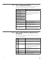
Step Description Reference Document
1 Initial Setup This document (Section 4)
2 Purging Steering
System
Optimus EPS Installation Manual (Book 65)
3 Calibration Optimus EPS Installation Manual (Book 50.1)
Optimus EPS Electronic Power Steering with
Electric Actuator Installation and User’s
Manual (Book 54)
4 Control Head and
Gateway Setup
This document (manufacturer-specific
sections 5-8)
5 Sea Trial Optimus EPS Installation Manual (Book 65)
6 Joystick Setup This document (Section 9)
Table 3-1. Component list and installation references.
Table 3-2. System setup order of operations.
Part 2 – System calibration, purging and setup
(Section 4.0)
The system calibration, purging and setup must be done in the correct
order as defined in Table 3-2.
3.2.2
Part 1 – Component installation
Components may be installed in any order. Table 3-1 shows where the
installation information can be found for each component.
3.2.1

3-3
EN
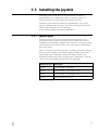
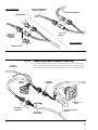
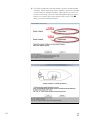
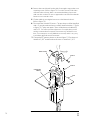
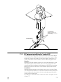
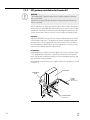
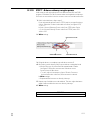
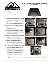
Install the joystick on the dash in an area that allows convenient,
unobstructed access. Whenever possible, mount the joystick on a
horizontal surface in a location that will minimize water spray.
Install the joystick using the hardware provided in the kit. The joystick
harnesses must be strain relieved to one of the mounting studs using the
cable tie provided with the joystick hardware.
A dash cutout template is provided in Appendix A.
3.3 Installing the Joystick
Joystick Part No. Description
EJ1400 Joystick, Master, Twin Engine
EJ1403 Joystick, Master, Triple Engine, Tiebar
EJ1404 Joystick, Master, Quad Engine, Tiebar
EJ1401 Joystick, Additional Station
Table 33. Available Joysticks.
Joystick types
There are two types of joysticks: master and additional station. Every
installation must have at least one master joystick, which comes factory
configured for the number of engines in the installation. The master joystick
can be installed at any control station – the joystick type is independent of
the joystick station.
If there is no master joystick in the system you will get a persistent “Missing
Master Joystick” warning on the CANtrak display. Similarly, if the master
joystick type doesn’t match the configured number of engines, the
CANtrak will display a persistent “Invalid Joystick Configuration” warning.
Table 3-3 lists the available joysticks at the time of printing.
3.3.1

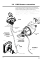
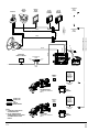
CM21504 HARNESS
TO CAN2
NETWORK
NODE
CAN1 HARNESS TO
PCM OR ELECTRIC
ACTUATOR
JOYSTICK
CAN2 PORT
(SEE SECTION 3.5)
HARNESSES MUST
BE STRAIN RELIEVED
TO JOYSTICK
MOUNTING STUD
USING CABLE TIES
PROVIDED
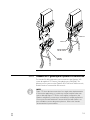
CANtrak
HARNESS TIE POINT X 4
HARNESS MUST BE
STRAIN RELIEVED TO HELM
HOUSING TAB USING
CABLE TIES PROVIDED
CAN1 HARNESS
TO HELM
ELECTRONIC
HELM
3-4
EN
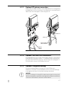
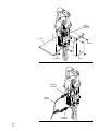
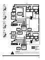
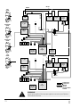
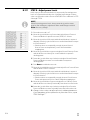
For CAN1 harness selection and connections refer to the Optimus EPS
Installation Manual (Book 50.1) or Optimus EPS Electronic Power Steering
with Electric Actuator Installation and User’s Manual (Book 54).
In addition to this, the Optimus 360 system requires a 6-pin CAN1 harness
connection between the steering helm and the joystick. Refer to Book 50.1
or Book 54 for proper harness selection and strain relieving.
In particular installations, a CAN1 wye harness (CM21702) or a CAN1 hub
(HA5497) may be required to make all necessary connections.
3.4 CAN1 Harness connections
Figure 3-1. CAN1 harness connections.

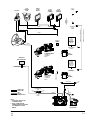
NETWORK TEES CM10060 OR
SIX-PORT HUB CM20064
NETWORK TEES CM10060 OR
SIX-PORT HUB CM20064
DEVICENET
HARNESS
DEVICENET HARNESS
4'
HARNESS
CM21504
POSSIBLE EST NETWORK
CONNECTION POINT
OPTIONAL AUTOPILOT
CONTROLLER
POSSIBLE EST NETWORK
CONNECTION POINT
MALE
TERMINATOR
CM10051
FEMALE
TERMINATOR
CM10052
CAN2 CONNECTION
OF PCM OR ELECTRIC
ACTUATOR(S)
JOYSTICK
COLOR
CANtrak
HATCH OR CONSOLE
MOUNTED COMPONENTS
OPTIMUS 360 DASH
MOUNTED COMPONENTS
3-5
EN
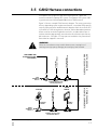
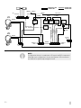
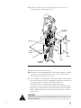
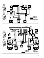
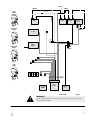
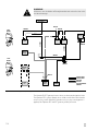
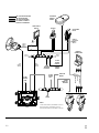
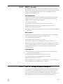
The Optimus 360 system uses the same CAN2 network, cables and
structure as the basic Optimus EPS system. The Optimus 360 system adds
a joystick and control head (if applicable) to the CAN2 network.
Figure 3-2 shows a sample CAN2 network diagram. The exact connections
will vary depending on the engine manufacturer; consult the OEM-specific
sections of this manual for detailed network diagrams. Refer also to Book 50.1
or Book 54 for CAN2 wiring, harness selection, and installation best practices.
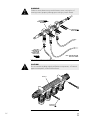
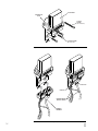
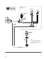
All tees must be secured using both screw holes, and the cable drops at
each tee must be appropriately secured and strain-relieved to prevent any
pull on the tees. See figure 3-3 for proper tee installation. Any unused tees
must either be capped or removed.
3.5 CAN2 Harness connections
Figure 3-2. Generic CAN2 wiring diagram.
WARNING!
Failure to secure harness may result in harness wear, causing loss of
steering control, property damage, personal injury and/or death.

SCREWS IN ALL
MOUNT HOLES
EACH CABLE
APPROPRIATELY
SECURED AND
STRAIN RELIEVED
CLOSE TO TEES
NO PULLING
ON TEES
ALL NUTS DOUBLE
CHECKED FOR TIGHTNESS
AND MARKED
NOTE: TEES MAY NOT LOOK
EXACTLY AS SHOWN
SCREWS IN ALL
MOUNT HOLES
CM20064
3-6
EN
WARNING!
Failure to secure harness may result in harness wear, causing loss of
steering control, property damage, personal injury and/or death .
CAUTION!
Do not connect anything other than Optimus components, or Dometic
approved autopilots, to the CAN2 network.
Figure 3-3. Correct CAN2 tee installation example.
Figure 3-4. Alternative CAN2 6-port hub connection.

4-1
EN
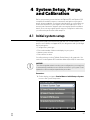
Figure 4-1.
4 System Setup, Purge,
and Calibration
The system setup is performed easily with the color CANtrak display. (If you
prefer to use Datalink, see Appendix B.) It is designed to walk you through
the following tasks:
• Configure the system type
• Choose the number of helms and displays in your system
• Update system software
• Select device locations
You will need access to the CANtrak Dealer Menu for all setup tasks. See
section 2.1 in the Optimus EPS Installation Manual (Book 65) for instructions.
Before you proceed you need to have all Optimus EPS and Optimus 360
components installed, harnesses connected, and ignition sensing and
power wiring completed. If you haven’t already done so you’ll need to go
to the section specific to your engine (section 5 through section 11) for
network interconnection diagrams and some engine-specific installation
details. Do not do any engine-specific setup or configuration at this time;
you will need to perform the initial setup first.
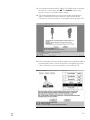
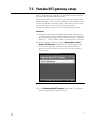
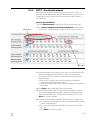
Procedure:
1. On the display, navigate to Dealer Menu > Initial Setup > System
to access the System Setup menu.
4.1 Initial system setup
NOTICE!
The software update wizard uses the system configuration you set up here
to automatically install the correct software revisions for your system. Don’t
update the software until prompted in the procedure.

4-2
EN
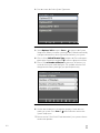
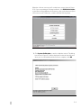
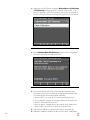
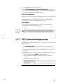
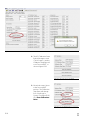
2. Press > to enter the Select System Type menu.
Figure 4-2.
Figure 4-3.
3. Select Optimus 360 then press Save or to return to the System
Setup menu. When you set the system type the CANtrak automatically
configures the menus to show only items that relate to your system.
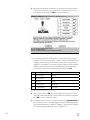
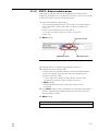
4. Choose Select Shift & Throttle Type and press >. Choose the appro-
priate option from the list and press
to return to the previous menu.
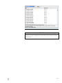
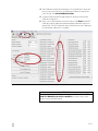
5. Choose Select Number of Devices and press >. The devices you
see in this list may not match the figure. The available selections will
change based on the system type you specified previously.
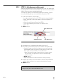
6. Use the + and – buttons to change the quantity of each device to
match your system. Press Save or
when finished to return to the
System Setup menu.
7. Review section 11.0 in Book 65 and determine if your system software
needs to be updated.
Page is loading ...
Page is loading ...
Page is loading ...
Page is loading ...
Page is loading ...
Page is loading ...
Page is loading ...
Page is loading ...
Page is loading ...
Page is loading ...
Page is loading ...
Page is loading ...
Page is loading ...
Page is loading ...
Page is loading ...
Page is loading ...
Page is loading ...
Page is loading ...
Page is loading ...
Page is loading ...
Page is loading ...
Page is loading ...
Page is loading ...
Page is loading ...
Page is loading ...
Page is loading ...
Page is loading ...
Page is loading ...
Page is loading ...
Page is loading ...
Page is loading ...
Page is loading ...
Page is loading ...
Page is loading ...
Page is loading ...
Page is loading ...
Page is loading ...
Page is loading ...
Page is loading ...
Page is loading ...
Page is loading ...
Page is loading ...
Page is loading ...
Page is loading ...
Page is loading ...
Page is loading ...
Page is loading ...
Page is loading ...
Page is loading ...
Page is loading ...
Page is loading ...
Page is loading ...
Page is loading ...
Page is loading ...
Page is loading ...
Page is loading ...
Page is loading ...
Page is loading ...
Page is loading ...
Page is loading ...
Page is loading ...
Page is loading ...
Page is loading ...
Page is loading ...
Page is loading ...
Page is loading ...
Page is loading ...
Page is loading ...
Page is loading ...
Page is loading ...
Page is loading ...
Page is loading ...
Page is loading ...
Page is loading ...
Page is loading ...
Page is loading ...
Page is loading ...
Page is loading ...
Page is loading ...
Page is loading ...
Page is loading ...
Page is loading ...
Page is loading ...
Page is loading ...
Page is loading ...
Page is loading ...
Page is loading ...
Page is loading ...
Page is loading ...
Page is loading ...
Page is loading ...
Page is loading ...
Page is loading ...
Page is loading ...
-
 1
1
-
 2
2
-
 3
3
-
 4
4
-
 5
5
-
 6
6
-
 7
7
-
 8
8
-
 9
9
-
 10
10
-
 11
11
-
 12
12
-
 13
13
-
 14
14
-
 15
15
-
 16
16
-
 17
17
-
 18
18
-
 19
19
-
 20
20
-
 21
21
-
 22
22
-
 23
23
-
 24
24
-
 25
25
-
 26
26
-
 27
27
-
 28
28
-
 29
29
-
 30
30
-
 31
31
-
 32
32
-
 33
33
-
 34
34
-
 35
35
-
 36
36
-
 37
37
-
 38
38
-
 39
39
-
 40
40
-
 41
41
-
 42
42
-
 43
43
-
 44
44
-
 45
45
-
 46
46
-
 47
47
-
 48
48
-
 49
49
-
 50
50
-
 51
51
-
 52
52
-
 53
53
-
 54
54
-
 55
55
-
 56
56
-
 57
57
-
 58
58
-
 59
59
-
 60
60
-
 61
61
-
 62
62
-
 63
63
-
 64
64
-
 65
65
-
 66
66
-
 67
67
-
 68
68
-
 69
69
-
 70
70
-
 71
71
-
 72
72
-
 73
73
-
 74
74
-
 75
75
-
 76
76
-
 77
77
-
 78
78
-
 79
79
-
 80
80
-
 81
81
-
 82
82
-
 83
83
-
 84
84
-
 85
85
-
 86
86
-
 87
87
-
 88
88
-
 89
89
-
 90
90
-
 91
91
-
 92
92
-
 93
93
-
 94
94
-
 95
95
-
 96
96
-
 97
97
-
 98
98
-
 99
99
-
 100
100
-
 101
101
-
 102
102
-
 103
103
-
 104
104
-
 105
105
-
 106
106
-
 107
107
-
 108
108
-
 109
109
-
 110
110
-
 111
111
-
 112
112
-
 113
113
-
 114
114


Dometic Optimus 360 Joystick Control System Installation guide
- Type
- Installation guide
Ask a question and I''ll find the answer in the document
Finding information in a document is now easier with AI
Related papers
-
Dometic EA1000, EA1100 Operating instructions
-
-
-
-
-
Seastar Solutions SeaStar BayStar Front Mount Helm Installation guide
-
-
-
-
Other documents
-
LG SU880 Optimus EX User manual
-
Seastar Solutions Optimus 360 Installation guide
-
 boatcommand BC-4001 User manual
-
Optimus 98578896M User guide
-
Hasbro Transformers Alternators 81327 Operating instructions
-
 Crown Automotive RT27022 Installation guide
-
-
Suzuki DF115A Owner's manual
-
-
Yanmar 3TNV88F User manual

