Page is loading ...

INSTRUCTION MANUAL
CAUTION: Read All Instructions Before Operating Equipment
MFJ ENTERPRISES, INC.
300 Industrial Park Road
Starkville, MS 39759 USA
Tel: 662-323-5869 Fax: 662-323-6551
COPYRIGHT 2011 MFJ ENTERPRISES, INC.
C
Model MFJ-9200
VERSION 1A

I
DISCLAIMER
Information in this manual is designed for user purposes only and is not intended to
supersede information contained in customer regulations, technical
manuals/documents, positional handbooks, or other official publications. The copy of
this manual provided to the customer will not be updated to reflect current data.
Customers using this manual should report errors or omissions, recommendations for
improvements, or other comments to MFJ Enterprises, 300 Industrial Park Road,
Starkville, MS 39759. Phone: (662) 323-5869; FAX: (662) 323-6551. Business hours:
M-F 8-4:30 CST.

INTRODUCTION
The MFJ-9200 is a bold new addition to MFJ's legendary QRP transceiver line,
delivering unmatched 6-band CW performance in a compact pocket-sized package.
QRP radios have always been small in size, but thanks to direct-digital synthesis and
microprocessor technology, the MFJ-9200 represents a quantum leap over traditional
designs with an unprecedented number of features at an affordable price.
The MFJ-9200 covers 80 through 15 Meters with computer-modeled plug-in filter
modules that yield no-compromise receiver performance and QRP+ transmit power on
every band. There's also built-in iambic keying with a manual-key sensor, a
programmable CQ message, and seamless QSK T/R switching. DDS frequency control
delivers rock-solid VFO stability, precise 100-Hz readout, and eight memory channels
per band. Plus, you get a choice of three main-dial tuning rates and RIT with 10-Hz
tuning resolution. Other features include selectable IF-bandwidth for monitoring SSB or
CW, a 20-dB front-end attenuator for overload protection, and a switched backlight for
the LCD display. There’s also plenty of receiver overlap for monitoring time signals and
international short wave broadcasting. The MFJ-9200 runs on any power source
between 8 and 15 VDC and draws 40 mA on receive with the display backlight turned
off -- perfect for prolonged off-the-grid adventures. Best of all, the MFJ-9200 is the
smallest and lightest backpack transceiver currently available.
In order to take full advantage of the MFJ-9200’s many operating features, please read
this manual carefully before attempting to set up and operate your QRP station. The
MFJ-9200’s microprocessor controls are surprisingly simple and intuitive to operate with
only a minimum of familiarization. Nevertheless, as with any electronic device, failing to
follow the prescribed set-up and operating instructions could result in permanent
damage. Once you become familiar with basic setup and operating procedures, feel
free to use the Quick Menu in the back of the manual as a refresher.
Important Warning: Before attempting to operate your MFJ-9200 on air, please read
through the entire manual. Failing to adhere to prescribed setup and operating
recommendations could result in permanent damage to your radio!

SPECIFICATIONS
Frequency Control: DDS, 60-MHz reference frequency
VFO Tuning Steps: 100-Hz, 1-kHz, and 100-kHz
RIT Step: 10-Hz
VFO Memories: 8 per band
VFO Display: LCD, 802-pixel, switched backlight
VFO Display Frequency Resolution:
100-Hz, 10-Hz with RIT activated
Operating Modes:
Transmit - A1 (CW), Receive - A1, A3J (LSB or
USB)
CW Offset: ~700 Hz
T/R Switching: Full QSK
Frequency Coverage, MHz:
Band
80-
M
40-
M
30-
M
20-
M
17-M 15-
M
Receiv
e
(MHz)
3.24
-4.9
5.9-
7.5
9.4-
12.1
13.5
-
15.8
17.4-
19.1
18.5
-
22.0
Trans
mit
(MHz)
3.5-
4.0
7.0-
7.3
10.1
-
10.1
5
14.0
-
14.3
5
18.06
8-
18.16
8
21.0
-
21.4
5
Receiver MDS: 0.1-uV, all bands
AGC Threshold: 3 to 5-uV, all bands
Bandwidth: Selectable, 600-Hz CW, 2.5-Hz SSB
Audio Output: 100-mW, 8-Ohm load, stereo plug
Receiver Current Drain:
~40-mA no backlight, ~80 mA with backlight
Transmitter Keying:
Iambic with straight-key sensing, Auto-CQ memory
Speed Range: 3-45 WPM
Transmitter Power:
5-W or better, all bands, at 12.6 Volts
Harmonic and spur suppression:
-50 dB or better, all operating voltages
Typical Transmit Current: 0.9-A at 10-V, 1.2-A at 14-V
Supply Voltage: 8-15 VDC at 1.5A
Dimensions: 4.8”x3.15”x1.34”, 120x80x34-mm
Weight: 7.4 oz, 200 gm

CONNECTIONS
Power Source: Use any well-filtered DC power supply or battery pack with output in the
8-15 VDC range and capable of 1.5-Amps or more. DO NOT connect the MFJ-9200 to a
source exceeding 15 VDC or permanent damage may result.
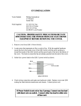
Power Connection: Use a standard 2.1-mm concentric power plug with plus (+)
connected to the center and ground (-) connected to the outer sleeve. The MFJ-9200
has a built-in series diode to protect against accidental reverse-polarity connection, but
we also strongly recommend fusing the plus (+) lead of your power source at 2-A to
provide over-current protection in the event of an accidental short or component failure.
+
_
2-A Fuse
2.1-mm Plug
Antenna: The antenna jack accepts a standard BNC male connector or BNC-to-UHF
adapter, as required. Connect any coax-fed resonant antennas with SWR measuring
under 2:1 directly to the radio. Antennas exhibiting higher SWR or using balanced
feeders should be matched to 50-Ohm unbalanced line using an external antenna tuner
(ATU). Never intentionally transmit into high-SWR loads, as extreme mismatch may
cause the radio to emit out-of-band signals exceeding FCC guidelines. A prolonged
high-SWR condition may also damage internal components.
Headphones: Use any 8 to 32-Ohm stereo headset outfitted with a 3.5-mm stereo plug.
Note that the radio’s audio output circuit is not wired to accept monaural plugs.
Connecting phones or a speaker wired with a monaural plug will shunt the audio signal
to ground. To obtain monaural output, use a 3.5-mm stereo plug and leave the ring
disconnected.
Tip
Ring
Sleeve
Right
Left
Ground
Tip
Ring
Sleeve
Ground
NC
Audio
Stereo Phones
Monaural Phones
Paddle or Straight-key Wiring: Configure paddles with a 3.5-mm stereo plug. Connect
the dot contact to the tip, dash contact to the ring, and ground to the sleeve. Configure
manual keys using a monaural plug with the contactor connected to the tip. If using a
stereo plug with a manual key, connect both the ring and sleeve to ground.
Tip
Ring
Sleeve
Dot
Dash
Ground
Tip
Sleeve
Ground
Contactor
Paddles Manual Key - Monaural Plug
Tip
Ring
Sleeve
Ground
Ground
Contactor
Manual Key - Stereo Plug

TRANSCEIVER OPERATION
Installing Band Modules: Prior to powering up, identify and install the filter module for
the band you intend to use. The band is marked on the filter pc board. To access plug-in
headers for the module, remove the two knurled screws securing the radio’s case and
slide off the back.
Antenna
Module Header
Module Header
Standoff
Antenna
Band Label
Module
Screw
Band Module
The band-module headers are located directly below the BNC antenna connector. Line
up the module and install it component-side down, as shown. Fasten in place using the
module retention screw and reinstall the case. Note that the retention screw should
always be used to ensure firm seating and good grounding. Also, note that a filter
module must be installed for the DDS to recognize a band of operation.
Key Detection: The MFJ-9200 features a key-detection circuit. The sensing circuit
initializes each time the radio is powered up. If paddles are connected or if no key is
installed, the keyer initializes in Automatic Mode and sends the letter A in code. If a
straight key is installed when the radio is powered up, the keyer senses Manual Mode
and sends the letter M.
Important Note: The radio’s default is Automatic Mode. If a manual key is plugged in
after the radio is powered up, the radio will transmit a continuous string of dashes until
the key is unplugged or the radio is rebooted. This condition occurs because the keyer
misinterprets the manual key’s monaural plug as a ring-to-sleeve contact closure. To
correct it, simply switch the power off and turn it back on again to re-initialize the keyer.
Power On: After connecting a power source, antenna, headphones and key, you’re
ready to begin. It may prove helpful to have your radio set up and connected to a
dummy load when going through this portion of the manual so you can check out each
function without causing on-air interference. Using the POWER switch located on the
front panel, power up the radio and set VOLUME for a comfortable listening level.
Boot Screen: During power-up, the LCD screen displays the selected band. Example:
[Band-20m]. Also, the keyer side-tone sends the letter A or M in code to identify the
type of key that is plugged in.

Operating Screen: After two seconds, the boot screen switches to an operating screen
that displays the following information:
(1.) Upper-left: Shows IF bandwidth [CW] or [LSB]/[USB] (depends on band in use).
Every four seconds, this readout momentarily switches to show power supply voltage.
Example: [12.6].
(2.) Upper-right: Shows VFO status. A [V] means the tunable VFO is active and [M]
indicates the Memory Mode is selected (see MEM-VFO). The adjacent number [1-8]
shows the current memory channel. When power is applied, the radio comes up in
Memory Mode [M].
(3.) Lower Line: Shows the radio’s active operating frequency for the VFO or memory
channel. Resolution is normally 100-Hz, but diverts to 10-Hz when the RIT is activated.
Band Error: If no filter module has been installed, the display will flash [BAND-???] to
alert you that a module needs to be installed.
Transmit Error: If the transmitter is keyed while the VFO is tuned outside the amateur
band, the top line of the display flashes [TX ERROR] and transmission is blocked.
Push-Button Controls: Front-panel switches control most transceiver functions. There
are five red pushbuttons plus a momentary push-in switch built into the TUNE knob.
Four switches activate more than one function and require two types of user input. The
primary switch-input is a momentary press. The secondary switch-input is a two-second
press and hold. The manual instructions are “tap” for a short input and “depress” for a
long input.
MEM-VFO Switch: To toggle between VFO and MEMORY, tap the MEM-VFO switch.
In Memory mode, [M] is displayed and the TUNE knob is used to scroll through the
channels. The radio normally boots up in memory mode.
In VFO mode, [V] appears on the display and the TUNE knob changes operating
frequency. Note that the number of the most recently selected memory channel [1-8] is
displayed in both the VFO and Memory modes (many synthesized radios and HTs use
a similar VFO/Memory setup).
To load a VFO Frequency into Memory (VFOÆMem):
[ ] Tap MEM-VFO to [M] and rotate TUNE to select a desired memory channel [1-8].
[ ] Tap MEM-VFO to [V] and rotate TUNE for the exact frequency you wish to store.
[ ] Depress MEM-VFO to move the VFO frequency into memory. [Save] confirms
completion.

To retrieve a Frequency from Memory (MemÆVFO):
[ ] Tap MEM-VFO to [M] and rotate TUNE to select the memory channel you wish to
recall [1-8].
[ ] Tap MEM-VFO to [V] to transfer it into VFO mode. You may now tune up or down
the band.
[ ] To update the original stored frequency with a new frequency, depress MEM-VFO.
[Save] will flash on the display to confirm completion. If you don’t save a new frequency,
the original entry will be retained in memory.
TUNE Switch: The TUNE knob has a momentary press-down switch for selecting
tuning steps.
[ ] To toggle between 100-Hz and 1-kHz tuning steps, tap TUNE. The frequency
display momentarily underlines the tuning increment you select [ _ ].
[ ] To select 100-kHz tuning steps for rapid QSY between band segments, depress the
TUNE knob. After shifting band segments, depress TUNE again to restore normal fine-
tuning.
RIT-MODE Switch: Activates RIT function, plus controls bandwidth and sideband
selection.
[ ] To use incremental tuning, tap RIT to toggle it on and off. When active, the
frequency display shifts to 10-Hz resolution and a dash symbol [-] appears to the right of
the last digit. The dash symbol [-] signifies zero RIT shift. Rotate TUNE clockwise to
move above zero-shift and note that an up-arrow [↑] appears on display. When tuning
below zero shift, [↓] appears. To restore zero-shift, tune opposite the arrow until the
dash reappears [-]. The normal RIT tuning step is 10 Hz.
[ ] To select bandwidth, depress MODE to toggle between narrow [CW] and wide [LSB
or USB]. The processor selects the appropriate sideband designation, depending on the
band.
ATT Switch
: Tap to toggle the attenuator on or off. Receive attenuation is
approximately 20 dB.
BL Switch
: Tap to toggle the display’s backlight on or off. Off conserves power when
operating on batteries.
CALL Switch
: Initiates an automatic CQ. Also selects several keyer setup functions.
Keyer setup functions require connecting a set of paddles to the radio.
[ ] Call CQ: Tap CALL. The keyer will automatically transmit a complete CQ sequence,
inserting the call letters that have been programmed into memory.

[ ] Adjust Keyer Speed: Depress and hold CALL until you hear the letter S played
back in code. Release CALL, and within five seconds, press and hold the DOT paddle
to increase speed or press and hold the DASH paddle to decrease speed. The sidetone
provides audible feedback as the speed changes. When a comfortable rate is found, tap
CALL once to exit. The letter E confirms completion of the programming sequence.
[ ] Enter Your Call into CQ Memory: Depress and hold CALL until you hear the letter
I (which will follow S by a few seconds). When you hear I, release the CALL button and
send your call letters in normal fashion using the paddles. When finished, tap CALL
once to exit.
[ ] Test Carrier: Depress and hold CALL until you hear the letter T (follows S and I).
When you hear T, release the CALL button and press the DASH paddle to initiate a
continuous carrier. Press the DOT paddle to turn it off. To escape from Transmit Carrier
mode, tap the CALL button. The letter E will confirm your exit. The Test Carrier function
allows you to lock the key down when using paddles to take SWR readings or make
tuner adjustments.
TRANSCEIVER CARE AND MAINTENANCE
The MFJ-9200 has no internal “user” adjustment and is designed to be maintenance
free. To preserve the finish, avoid using harsh chemical cleaners on the cabinet or on
plastic parts. When backpacking or boating, keep the radio dry by sealing it in a Baggie
or Pelican case during transport. If it should become wet, remove the back of the case
and allow all circuitry to dry out for an extended period before powering up. Do not
power up if you observe condensation in the LCD window, and avoid heating at high
temperature to accelerate drying. Better to seal it in a container with a desiccant
capsule to draw the moisture out at room temperature.
TECHNICAL ASSISTANCE
If you have a problem with your radio, first check all external plugs and cables for shorts
or opens and confirm that your antenna is working properly with low SWR. Also, check
the operating voltage of the power supply or battery pack and review the radio’s various
functions to confirm that you haven't inadvertently reset a critical operating parameter. If
the problem persists, you may call MFJ Technical Services at 662-323-0549 or the MFJ
Factory at 662-323-5869. Have your unit, the manual, and all pertinent information
about your station handy so you can answer any questions the technician may ask.
You may also send questions by mail to MFJ Enterprises, Inc., 300 Industrial Park
Road, Starkville, MS, 39759 or e-mail [email protected]. Be sure to include
a complete description of the problem and an exact description of your operating setup
and conditions.

MFJ-9200 Quick Reference Menu:
MEM-VFO
RIT-MODE
BL CALL AF GAIN
ATT
TUNE
POWER
Key-Paddle Phone
Ant
Power
ON
12
3
Connections:
Power: 2.1-mm plug, grounded sleeve, positive (+) center, supply 8-15 VDC @ 1.5A.
Antenna: BNC male or BNC-UHF adapter, 50-Ohms unbalanced, SWR 2:1 or less.
Paddle: 3.5-mm plug, dot to tip, dash to ring, ground to sleeve.
Straight Key: Contactor to tip, ground to ring, ground to sleeve (or use a mono plug).
Headphone: 3.5-mm stereo, right channel to tip, left channel to ring, ground to sleeve.
Display Window:
Segment 1: RX Mode [CW] or [USB, LSB], supply voltage flashes every 4 seconds -
Ex [12.6]
Segment 2: [V] = VFO mode, [M] = Memory mode, [1-8] = number of memory channel
Segment 3: Frequency Display, 100-Hz readout normal, 10-Hz with RIT.
Control Switch Functions:
MEM-VFO: Tap for [M] or [V]
Press to enter displayed frequency to memory: VFO ÆMEM
TUNE: ROTATE TO TUNE VFO FREQUENCY OR TO SCROLL MEMORY
CHANNELS [1-8].
TAP TO TOGGLE FINE-TUNE RATE (100 HZ, 1 KHZ).
PRESS TO ENTER OR EXIT FAST TUNE RATE (100 KHZ).
ATT: TAP TO TOGGLE 20-DB ATTENUATOR ON OR OFF.
BL: TAP TO TOGGLE BACKLIGHT ON OR OFF.
CALL: TAP TO CALL AUTO-CQ.

Keyer Functions:
[ ] SET KEYER SPEED: DEPRESS CALL AND HOLD FOR S, SET SPEED WITH
PADDLES, TAP TO EXIT.
[ ] ENTER CALL IN CQ MEMORY: DEPRESS CALL AND HOLD FOR I, ENTER
CALL WITH PADDLES, TAP TO EXIT.
[ ] CARRIER: DEPRESS CALL AND HOLD FOR T, HIT DASH TO ACTIVATE AND
DOT TO DEACTIVATE. TAP TO EXIT.

LIMITED 12 MONTH WARRANTY
MFJ Enterprises, Inc. warrants to the original owner of this product, if manufactured by MFJ
Enterprises, Inc. and purchased from an authorized dealer or directly from MFJ Enterprises, Inc.
to be free from
defects in material and workmanship for a period of 12 months from date of purchase provided
the following terms of this warranty are satisfied.
1. The purchaser must retain the dated proof-of-purchase (bill of sale, canceled check, credit card
or money order receipt, etc.) describing the product to establish the validity of the warranty claim
and submit the original or machine reproduction of such proof of purchase to MFJ Enterprises,
Inc. at the time of warranty service. MFJ Enterprises, Inc. shall have the discretion to deny
warranty without dated proof-of-purchase. Any evidence of alteration, erasure, or forgery shall
be cause to void any and all warranty terms immediately.
2. MFJ Enterprises, Inc. agrees to repair or replace at MFJ's option without charge to the original
owner any defective product under warrantee provided the product is returned postage prepaid to
MFJ Enterprises, Inc. with a personal check, cashiers check, or money order for $10.00 covering
postage and handling.
3. This warranty is NOT void for owners who attempt to repair defective units.
Technicalconsultation is available by calling the Service Department at 662-323-0549 or the
MFJ Factory at 662-323-5869.
4. This warranty does not apply to kits sold by or manufactured by MFJ Enterprises, Inc.
5. Wired and tested PC board products are covered by this warranty provided only the wired and
tested PC board product is returned. Wired and tested PC boards installed in the owner's cabinet
or connected to switches, jacks, or cables, etc. sent to MFJ Enterprises, Inc. will be
returned at the owner's expense unrepaired.
6. Under no circumstances is MFJ Enterprises, Inc. liable for consequential damages to person or
property by the use of any MFJ products.
7. Out-of-Warranty Service: MFJ Enterprises, Inc. will repair any out-of-warranty product
provided the unit is shipped prepaid. All repaired units will be shipped COD to the owner. Repair
charges will be added to the COD fee unless other arrangements are made.
8. This warranty is given in lieu of any other warranty expressed or implied.
9. MFJ Enterprises, Inc. reserves the right to make changes or improvements in design or
manufacture without incurring any obligation to install such changes upon any of the products
previously manufactured.
10. All MFJ products to be serviced in-warranty or out-of-warranty should be addressed to:
MFJ Enterprises, Inc.
300 Industrial Park Road
Starkville, Mississippi 39759 USA
and must be accompanied by a letter describing the problem in detail along with a copy of your
dated proof-of-purchase.
11. This warranty gives you specific rights, and you may also have other rights which vary from
state to state.
/