
INSTRUCTIONS AND PRECAUTIONS
Distributed exclusively by Harbor Freight Tools
®
.
3491 Mission Oaks Blvd., Camarillo, CA 93011
Visit our website at: http://www.harborfreight.com
SAVE THESE INSTRUCTIONS. READ ALL
PRECAUTIONS AND INSTRUCTIONS.
Copyright
©
2008 by Harbor Freight Tools
®
. All rights reserved. No portion of this document or any artwork contained
herein may be reproduced in any shape or form without the express written consent of Harbor Freight Tools.
Diagrams within this document may not be drawn proportionally. Due to continuing improvements, actual product
may differ slightly from the product described herein.
For technical questions or replacement parts, please call 1-800-444-3353.
MINI TRIPLE GAUGE SET
65210

SKU 65210 For technical questions, please call 1-800-444-3353. Page 2
UNPACKING
When unpacking, make sure the item is
intact and undamaged. If any parts are missing
or broken, call Harbor Freight Tools at the number
shown above as soon as possible.
IMPORTANT SAFETY
INFORMATION
Install only on 12 VDC, negative ground 1.
vehicles.
Make sure that bracket and posts are unbent 2.
before connecting.
Verify that there are no short circuits before 3.
reconnecting. Check for loose strands of
wire, in addition to direct contact with ground-
ed components. Use a multimeter with a
continuity function to help verify that there
are no shorts to ground. When reconnect-
ing, be prepared to disconnect battery again
immediately in the event that an unexpected
short circuit causes sparking.
Turn off car engine and set emergency brake 4.
before installing.
Do not place tubing near any hot exhaust 5.
system components during installation.
Wear ANSI-approved safety goggles and 6.
heavy-duty work gloves during assembly.
WARNING:7. The brass components of this
product contain lead, a chemical known to
the State of California to cause birth defects
(or other reproductive harm). (California
Health & Safety code § 25249.5, et seq.)
Disconnect vehicle battery negative terminal 8.
before installation.
Only use in accordance with State, local, 9.
Federal and D.O.T. laws and regulations.
Insulate connections to prevent re.10.
Keep installation area clean and well lit.11.
Keep bystanders out of the area during 12.
installation.
Do not install when tired or when under the 13.
inuence of drugs, alcohol or medication.
This product is not a toy. Do not allow chil-14.
dren to play with it.
Use for intended purpose(s) only.15.
Inspect before use; do not use if parts are 16.
loose or damaged.
Positive and negative connections cannot 17.
touch. If you are unsure of how to install this
Gauge Set safely, then have a qualied me-
chanic install the gauge for you.
Maintain product labels and nameplates. 18.
These carry important safety information.
If unreadable or missing, contact Harbor
Freight Tools for a replacement.
INSTALLATION INSTRUCTIONS
Read the ENTIRE IMPORTANT
SAFETY INFORMATION section at the
beginning of this document including
all text under subheadings therein
before set up or use of this product.
Select a position on the dash for
mounting the Gauge Set. Drill 7/8” hole
in rewall and insert bulb tube and tting
through hole. Use holes in Gauge Set
Frame to mount the Set on dash.
Follow the specic instructions listed
below for installing each Gauge.
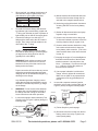
Oil Pressure Gauge
Remove oil light sender from the side of the 1.
engine block and disconnect the wire from
the indicating light on the dashboard.
Connect the coiled end of the tubing to the 2.
engine block (where the oil light sender
was removed) and the other end to the Oil
Pressure Gauge. Use plumber’s putty (not
included) to prevent any high pressure leaks.
See Figure 1, below.
Figure 1
Dash Panel
Oil Gauge
1/8 Tube to NPT
Connector
1/8"
1/8"
"T" Piece
To lighting circuit
Union
Nut
Tubing
1/8"
Union Nut
Adaptor
1/8"
Engine Block
1/8" Tube to
Male NPT
Connector
1/4" NPT to 1/8"
NPT Reducer
(Used on engines
with 1/4" Oil Tap)

SKU 65210 For technical questions, please call 1-800-444-3353. Page 3
When required, use adaptor bushings on all 3.
cars that have larger oil gallery taps. See
chart below for typical gallery tap sizes.
Ford 1/4"
GM 1/8" (Most)
Chrysler 1/8" and 1/4"
Independent
(Rambler, Willys)
1/8"
To install Oil Pressure Gauge with function-4.
ing indicator light, insert bushing, nipple and
“T” tting (not included) in place of present oil
light sending unit on side of the engine block.
Connect the tubing to one side of the “T” 5.
tting and the other end to the Oil Pressure
Gauge. Then connect oil light sender to the
other side of the “T” tting.
Ammeter Gauge
NOTE:1. To install Ammeter correctly, make
sure that all added wiring is the same gauge
(or larger) as the wiring found on the car
(typically #12 or #10 AWG).
WARNING! Break existing connection and
mount Ammeter in series. Do not connect
between the heavy wires that run from the
battery and to the starter.
Proper connection will insure that any current
drains that exceed the alternator/generator
charging rate will be indicated as negative (-)
discharge on the Gauge.
Any alternator/generator charging current
output that exceeds the total battery current
drain will be indicated as positive (+) charge
on the Gauge
WARNING!2. Do not connect wires between
the brass hex nuts and washers at back of
the Gauge Set case. Doing so can lead to
loose connections and erratic operation.
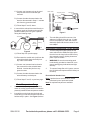
In cars with magnetic starter switches (Ford, 3.
Chrysler) refer to Figure 2 (below) during the
following steps:
A.) Mount Ammeter where desired and route
the wires from Ammeter through the re
wall and to the magnetic starter switch.
B.) At the large solenoid terminal, disconnect
all wiring EXCEPT for the heavy battery
cable.
C.) Gather all disconnected wires and group
together using a nut and bolt.
D.) Connect one Ammeter wire to the group
of wires and insulate to prevent wires from
touching chassis, body or engine of car.
E.) Connect other Ammeter lead wire to mag-
netic starter switch terminal, where the
heavy battery cable connects. (This is the
same terminal where wires were removed
in step “b”).
F.) Keeping the engine off, turn headlights on
and observe the direction of the Ammeter
needle movement. It should point to the
left or “-” (discharge). If it points to the right
or “+” (charge), reverse the position of
wires at rear of Ammeter.
G.) Once proper indication is achieved on
Gauge, securely tighten all connections.
Make sure no parts of any exposed wire
conductors touch any grounded part of
the car.
In cars with a separate mounted junction 4.
terminal or a horn relay (such as GM) refer to
Figure 3 (below) during the following steps:
A.) Follow Step A on previous page.
B.) Disconnect the wire running from the hot
battery post to horn relay or junction ter-
minal (usually black).
Figure 3
To Starter Mounted
Solenoid
Ammeter
Horn
Relay
Battery
Starter
Switch
To Starter
Battery
Ammeter
Figure 2

SKU 65210 For technical questions, please call 1-800-444-3353. Page 4
C.) Connect one Ammeter wire to the termi-
nal post where the hot lead was just
removed.
D.) Connect the other Ammeter lead to the
hot wire disconnected in Step C. Insulate
wire from any ground contact.
E.) Follow Steps F and G, above.
In cars with the solenoid mounted directly on 5.
the starter (such as Chrysler and most inde-
pendent models) refer to Figure 4 (below)
during the following steps:
A.) Follow Step A on previous page.
B.) Disconnect the smaller wire (red) from the
solenoid terminal where the heavy bat-
tery cable is terminated.
C.) Connect one Ammeter lead to the wire
just removed from the solenoid batter
terminal. Insulate the joint from any
ground contact.
D.) Connect the other Ammeter lead to the
solenoid battery terminal post.
E.) Follow Steps F and G, on previous page.
Water Temperature Gauge
Locate suitable opening in engine block to 1.
reach the cooling system water or locate the
presently installed water temperature sender.
Inset bulb on end of tube into the hole and 2.
screw tting on tube into the hole until bulb is
held securely in place. See Figure 5, above.
The tube tting should t most cars. Use 3.
adaptors (included) if they do not. If adap-
tors do not properly t, check with vehicle
dealership parts and services center for cor-
rect adaptor.
Illuminating Instructions For All Gauges
To have Gauge Set lights operate off the 1.
same switch as the dashboard light, splice
the wire from the lamp bulb socket into any
wire presently used for lighting instrument
panel. Tape to insulate.
WARNING!2. Be sure that mounting panel
is electrically grounded to chassis of car to
ensure steady gauge indications and light
intensity.
To connect Gauge Set to 6V system, remove 3.
the 12V bulbs and replace with 6V bulbs (not
included.)
Record Serial Number Here:
Note: If product has no serial number, record
month and year of purchase instead.
Note: No replacement parts are available.
Figure 4
Battery
Starter
Starter
Mounted
Solenoid
To Hot Wire
Figure 5
Gauge
Capillary Tubing
Dash Panel
Special Adaptor
Water Jacket
To Lighting Circuit
Thermo Bulb
-
 1
1
-
 2
2
-
 3
3
-
 4
4


Ask a question and I''ll find the answer in the document
Finding information in a document is now easier with AI
Related papers
Other documents
-
Harbor Freight Tools 98475 User manual
-
-
-
Chicago Electric 93784 User manual
-
-
Power Fist 4230069 Owner's manual
-
-
-
Pittsburgh Automotive Item 60278 Owner's manual
-