Page is loading ...

IMPORTANT: Fixture should be installed by a qualified
electrician to ensure proper wiring and installation.
Dimmable with ELV dimmer switches.
INSTALLATION INSTRUCTIONS FOR P5273-613-L
For Wall Mount Fixture
WARNING! SHUT POWER OFF AT FUSE OR CIRCUIT BREAKER.
AV E R T I S S E ME N T! CO U P E R L E C O U R A NT A U N I V E A U D E S F U S I B L E S O U D O D I SJ ON C T E U R .
AV E R T I S S E M E N T ! C O U P E R L E C O U R A N T A U N I V E A U DE S F US I B L E S O U D O D I S J O N C T E U R .
PREPARATION
1. Shut off power at the fuse box or circuit breaker box. If
necessary remove the old fixture and mounting hardware.
2. Carefully unpack your new fixture and lay out all the parts
on a clear area. Take care not to lose any small parts
necessary for installation.
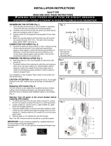
MOUNTING THE FIXTURE (FIG. 1)
3. Use the “key holes” located on the mounting plate (B) as a
template to mark the location of the plastic anchors (E) and
pre-drill two holes
4. Install the plastic anchors (E) into the wall.
5. Secure mounting back plate (B) to junction box (A) using
junction boxes screws (C) (Size: 8-32*1/2”L). The side of
the mounting back plate marked “GND” must face out.
6. Align the “key holes” on the mounting plate (B) to the
plastic anchors (E) and secure with screws (I).
CONNECTING THE WIRES (FIG. 2)
7. At this point, connect the electrical wires as shown in Fig. 2,
making sure that all wire connectors are secured. If your
outlet has a ground wire (green or bare copper), connect
the fixtures ground wire to it. Otherwise, connect the fixture
ground wire directly to the back plate (B) using the green
screw provided. After wires are connected, tuck them
carefully inside the junction box.
FINISHING THE INSTALLATION (FIG.1)
8. Using allen wrench (J) to loosen allen screw (K) a little.
Push rod (G) upwards and then lean glass shade (H) into
heat sink (D).
9. Tighten rod (G) and then also tighten screw (K) using allen
wrench (J).
10. Fix the bracket (L) to the mounting back plate (B) by using
screws (F).
Your installation is now completed. Return power to the junction box
and test the fixture.
CAUTION /ATTENTION: When handling the fixture, do not
apply pressure to the LEDs. Hold the fixture by the base or
bracket (L).
Replacing LED module (Fig. 3)
The LED module can be replaced by a qualified electrician
without cutting of wire and without damage to any decorative
element to which the fixture is attached. See installation steps
for more details (Fig 3.)
a. Shut off power. Remove the fixture from the wall.
b. Using allen wrench (J) to loosen allen screw (K) a little.
Push rod (G) upwards and then release glass shade (H)
from heat sink (D)(Fig.1).
c. Release black and white wires from quick connector on
LED module with using screwdriver by lightly pressing on
the release button located on the top of the wire connector.
d. Remove screws (N) and washers (M) to disconnect LED
module (N) from heat sink (D).
e. Reverse steps a-d for installing the new LED module.
Note: The LED module should be provided by a specified
supplier.
FIG.1
Set # A-021-460112
- Mounting plate - Ground screw
- Mounting screw*2pcs
Fig.2
FIXTURE
WIRES
Black or
Smooth
HOUSE
WIRES
Black
(Hot)
FIXTURE
WIRES
White or
Ribbed
HOUSE
WIRES
White
(Neutral)
FIXTURE
WIRES
Bare
Copper
(Ground)
HOUSE
WIRES
Green or
Bare
Copper(G
round)
FIG.3
/