Operator’s Manual
HD-350 Power Source+HD-4 Wire Feeder
Warning! Please read Owner’s Manual before installation, operation or repair of Crossfire welding
equip
ment.
WARNING! * ONLY QUALIFIED PERSONELL SHOULD OPERATE OR MAINTAIN THIS
MACHINE
* PLEASE READ THE OWER’S MANUAL BEFORE OPERATION ON
REPAIR OF WELDING MACHINE

Page 0
GENERAL SAFETY RYLES
WARNING:Read and understand all instructions. Failure to follow all instructions
listed below may result in serious injury.
CAUTION: Do not allow persons to operate or assemble this .HD-350 until they have
read this manual and have developed a thorough understanding of how IT works.
WARNING: The warnings,cautions,and instructions discussed in this instruction manual
cannot cover all possible conditions or situations that could occur.It must be understood by the operator
that common sense and caution are factors which cannot be built into this product.but must be supplied
by the operator.
1.1 Your Welding Environment
-Keep the environment you will be welding in free from flammable materials.
-Always keep a fire extinguisher accessible to your welding environment.
-Always have a qualified person install and operate this equipment.
-Make sure the area is clean, dry and ventilated. Do not operate the welder in humid, wet or poorly ventilated
areas.
-Always have your welder maintained by a qualified technician in accordance with local, state and national
codes.
-Always be aware of your work environment. Be sure to keep other people, especially children, away from
you while welding.
-Keep harmful arc rays shielded from the view of others.
-Mount the welder on a secure bench
or cart that will keep the welder secure and prevent it from tipping over or falling.
1.2 Your Welder’s Condition
-Check ground cable, power cord and welding cable to be sure the insulation is not damaged. Always replace
or repair damaged components before using the welder.
-Check all components to ensure they are clean and in good operating condition before use.
1.3 Use of Your Welder
Do not operate the welder if the output cable, electrode, MIG gun, wire or wire feed system is wet. Do not
immerse them in water. These components and the welder must be completely dry before attempting to use
them.
-Follow the instructions in this manual.
-Keep welder in the off position when not in use.
-Connect ground lead as close to the area being welded as possible to ensure a good ground.
-Do not allow any body part to come in contact with the welding wire if you are in contact with the material

Page 1
being welded, ground or electrode from another welder.
-Do not weld if you are in an awkward position. Always have a secure stance while welding to prevent
accidents. Wear a safety harness if working above ground.
-Do not drape cables over or around your body.
-Wear a full coverage helmet with appropriate shade (see ANSI Z87.1 safety standard) and safety glasses
while welding.
-Wear proper gloves and protective clothing to prevent your skin from being exposed to hot metals, UV and
IR rays.
-Do not overuse or overheat your welder. Allow proper cooling time between duty cycles.
-Keep hands and fingers away from moving parts and stay away from the drive rolls.
-Do not point MIG gun at any body part of yourself or anyone else.
-Always use this welder in the rated duty cycle to prevent excessive heat and failure.
1.4 Specific Areas of Danger, Caution or Warning
Electrical Shock
Electric arc welders can produce a shock that can cause injury or death. Touching electrically
live parts can cause fatal shocks and severe burns. While welding, all metal components
connected to the wire are electrically hot. Poor ground connections are a hazard, so secure the ground lead
before welding.
-Wear dry protective apparel: coat, shirt, gloves and insulated footwear.
-Insulate yourself from the work piece. Avoid contacting the work piece or ground.
- Do not attempt to repair or maintain the welder while the power is on.
-Inspect all cables and cords for any exposed wire and replace immediately if found.
-Use only recommended replacement cables and cords.
-Always attach ground clamp to the work piece or work table as close to the weld area as possible.
-Do not touch the welding wire and the ground or grounded work piece at the same time.
-Do not use a welder to thaw frozen pipes.
Fumes and Gases
-Fumes emitted from the welding process displace clean air and can result in injury or death.
-Do not breathe in fumes emitted by the welding process. Make sure your breathing air is clean and safe.
-Work only in a well-ventilated area or use a ventilation device to remove welding fumes from the
environment where you will be working.
-Do not weld on coated materials (galvanized, cadmium plated or containing zinc, mercury or barium). They
will emit harmful fumes that are dangerous to breathe. If necessary use a ventilator, respirator with air supply
or remove the coating from the material in the weld area.
-The fumes emitted from some metals when heated are extremely toxic. Refer to the material safety data sheet
for the manufacturer’s instructions.
-Do not weld near materials that will emit toxic fumes when heated. Vapors from cleaners, sprays and
degreasers can be highly toxic when heated.
UV and IR Arc Rays
The welding arc produces ultraviolet (UV) and infrared (IR) rays that can cause injury to your
eyes and skin. Do not look at the welding arc without proper eye protection.

Page 2
-Always use a helmet that covers your full face from the neck to top of head and to the back of each ear.
-Use a lens that meets ANSI standards and safety glasses. For welders under 160 Amps output, use a shade 10
lens; for above 160 Amps, use a shade 12. Refer to the ANSI standard Z87.1 for more information.
-Cover all bare skin areas exposed to the arc with protective clothing and shoes. Flame-retardant cloth or
leather shirts, coats, pants or coveralls are available for protection.
-Use screens or other barriers to protect other people from the arc rays emitted from your welding.
-Warn people in your welding area when you are going to strike an arc so they can protect themselves.
Fire Hazards
Do not weld on containers or pipes that contain or have had flammable, gaseous or liquid
combustibles in them. Welding creates sparks and heat that can ignite flammable and explosive
materials.
-Do not operate any electric arc welder in areas where flammable or explosive materials are present.
-Remove all flammable materials within 35 feet of the welding arc. If removal is not possible, tightly cover
them with fireproof covers.
-Take precautions to ensure that flying sparks do not cause fires or explosions in hidden areas, cracks or areas
you cannot see.
-Keep a fire extinguisher close in the case of fire.
-Wear garments that are oil-free with no pockets or cuffs that will collect sparks.
-Do not have on your person any items that are combustible, such as lighters or matches.
-Keep work lead connected as close to the weld area as possible to prevent any unknown, unintended paths of
electrical current from causing electrical shock and fire hazards.
-To prevent any unintended arcs, cut wire back to ¼" stick out after welding.
Hot Materials
Welded materials are hot and can cause severe burns if handled improperly.
-Do not touch welded materials with bare hands.
-Do not touch MIG gun nozzle after welding until it has had time to cool down.
Sparks/Flying Debris
Welding creates hot sparks that can cause injury. Chipping slag off welds creates flying debris.
-Wear protective apparel at all times: ANSI-approved safety glasses or shield, welder’s hat and ear plugs to
keep sparks out of ears and hair.
Electromagnetic Field
-Electromagnetic fields can interfere with various electrical and electronic devices such as
pacemakers.
-Consult your doctor before using any electric arc welder or cutting device.
-Keep people with pacemakers away from your welding area when welding.

Page 3
-Do not wrap cable around your body while welding.
-Wrap MIG gun and ground cable together whenever possible.
-Keep MIG gun and ground cables on the same side of your body.
Shielding Gas Cylinders Can Explode
High pressure cylinders can explode if damaged, so treat them carefully.
-Never expose cylinders to high heat, sparks, open flames, mechanical shocks or arcs.
-Do not touch cylinder with MIG gun.
-Do not weld on the cylinder
-Always secure cylinder upright to a cart or stationary object.
-Keep cylinders away from welding or electrical circuits.
-Use the proper regulators, gas hose and fittings for the specific application.
-Do not look into the valve when opening it.
-Use protective cylinder cap whenever possible
1.5 Proper Care, Maintenance and Repair
-Always have power disconnected when working on internal components.
- Do not touch or handle PC board without being properly grounded with a wrist strap. Put PC board in static
proof bag to move or ship.
-Do not put hands or fingers near moving parts such as drive rolls of fan.
HD-350USE AND CARE
● Do not modify the machine.in any way.Unauthorized modification may impair the function and/or safety
and could affect the life of the equipment.There are specific applications for which the machine.was
designed.
● Always check of damaged or worn out parts before using the machine.Broken parts will affect the units
operation.Replace or repair damaged or worn pats immediately.
● When HD-350 is not in use. store it in a secure place out of the reach of children.Inspect it for good
working condition prior to storage and before re-use.
Notice:* If the internal temperature exceess the safe zone the welder will shut down and the protection
indicator will light up.the welder will come back on when it cools down.
* Turn off the power switch and Argon valve.before leaving the woek area.
Shut off at end of day or temporary absences.
* Welders should wear canvas work clothes and welding face shield to protect from sparks and light rays.
* Put welding screens up to protect others in the work area.
* Flammable.explosive items should not be put near the welding area.
* Every outlet of the welder should be connected and grounded correctly.

Page 4
1. Product Description
This is a melting electrode gas shielded arc welder. It uses arc between wire and work piece as heat source
to melt wire and master material metal, and then sends shielded gas to welding site, which makes the arc,
melted wire, melt pond and master material metal free from
the atmosphere. The continuous wire can form
welding seam metal after melting so as to connect the work pieces each other. It is easy to
do all position
welding and
is widely used in manufacturing The HD series welder uses CO
2
as shielded gas and wire as
electrode, is an automatic gas shielded arc welder. It is suitable for low carbon, low alloy steel welding. Its
characteristics are saving energy, saving material, high efficiency, low cost etc. It can weld stainless steel with
mixed gas (CO
2
and Argon) as shielded gas if uses proper wire. The feature of CO
2
semi-automatic gas
shielded welder:
2. Safety Operation
2.1 Operator’s Protection
* Please always follow the rules that conform to safety. Wear protective garments to avoid injuries to eyes and
skin.
* Use A welding helmet to cover your head while working with the welding machine.
Use eye protection
when viewing the ARC
* Wear protection clothing.
* Do not operate under water.
* Fumes and gases produced when welding are hazardous to health. Make sure to work in places where there
is proper ventilation or use approved respiratory protection
* Please remember to keep arc rays away from the other people when welding.
2.2 Attention
* The voltage taps should not be changed while welding otherwise it will be damaged.
* Check the connection to see if the welder input and output cables are properly connected.
* Welders have strong electromagnetism and frequency interference,
people with pacemakers or other items
which can be interfered by electromagnetism and frequency.
Should not operate this machine.
*
Do not crush or kink the torch cable . The liner radius cannot less than 150mm, or it may damage the inner
cable.
* No switching when welding.
* The welder should use within rated duty cycle .Over load may accelerate the components aging
or
damaging the machine
* The gas bottle should be
secured to prevent tipping.
*
Do not touch the work piece. Power should be shut down if leaving the site temporarily.
2.3 Safety Measures to Be Taken To Assure the Correct Installation and Position
* Precaution must be taken to keep the operator and the machine from
overhead hazards.
* Inflammable or explosive materials are prohibited around welding site.
* The welder must be installed in the place where it can not be exposed to sun and rain. Also it must be stored
in less humid place with the temperature range at ﹣10 ~ 40℃.
* There should be 50 ㎝ space
around the welding machine to ensure ventilation.
* Make sure that there is no foreign body to enter the welding machine.
* No violent vibration in the welder’s surrounding area.
*
Do not operate in a strong wind since the welder is gas shielded.

Page 5
2.4 Safety Check
Each item listed below must be carefully checked before operation:
* Make sure that the welding machine has reliable
ground connection.
* Regular check needs to be conducted by the qualified personnel after the welder has been installed over a
period of six months, which involves as follows:
* Routine cleaning needs to be done to make sure that there is no abnormal loose parts happening in the
welding machine.
* Check the welding cable period for damage or wear.
* Replace the welder’s input cable as soon as it is found to be broken or damaged.
Notice: Cut off the power supply before opening the case to check.
* Ensure to install proper input voltage.
3. Technical Specifications
3.1 Working Environment
* The surrounding temperature range: when welding: water cooling: 5 ~
﹢
40℃,
During transport or in storage:﹣25 ~
﹢
55℃.
* Relative humidity: when at 40℃: ≤50%, when at 20℃: ≤90%.
* The dust, acid and
corrosive materials in the air can not exceed the amount required by the norm (apart from
the emissions from the welder). No violent vibration at the job site.
* Altitude no more than 1,000m.
*
Do not operate this machine in the rain.
* The wind speed should no more than 1m/s around the operation places.
3.2 Requirement for Main Supply
* The voltage oscillogram should display actual sine wave, the oscillation of the frequency should not exceed
±1% of the rated value.
* The oscillation of the supplied voltage should not exceed ±10% of the rated value.
* The three phase power supply unbalance rate ≤5%.
3.3 Welder Type Coding
3.4 Applying Standard of Welder
The Compact HD series Semi-automatic gas shielded welder according to the following standard:
IEC 60974-1;CSA approval.
3.5 Welding Principles (Refer To Circuit Diagram)
The HD series welder is silicon rectifier with flat characteristic DC arc welder. It adjusts open circuit
voltage by means of combined switch so as to attain the purpose of adjusting arc voltage; The main
transformer provides low AC voltage which isolated with power net; The reactor filters DC and controls its
movement characteristic, making the output current stable & continuous and better meet the requirements of
welding; Controlling board provides electrical and logical controlling function and wire feeding device power.
It can carry stepless change to wire feeding motor speed by means of speed potentiometer. The feeding speed
directly influences the size of welding current. Under matched voltage, the wire feeding is faster, the current is
larger.
The welder process is as follows:
HD - 350
Rated welding current(A)

Page 6
Torch Frame Sketch
Start — Pre-send Gas (0.3-0.6s) — Turn On Power Source — Feed Wire / Pilot Arc — Start Welding —
Stop Wire Feeding — Cut off Power — Stop Gas (lag2-3s)
3.6 MIG Torch Maintenance
Notice: * Shut off the power before assemble/disassemble torch or replace the components.
* Replace torch parts that are worn or damaged.
* The cable of torch must be replaced when it worn out.
* Use compressed air to blow out dust/deris from torch regularly.
3.7 Remark & Sign of Illustration
Ground
MIG/MAG Welding
AC 3-phase Power Supply, the Rated Frequency is 60Hz.
3-phase Transformer—Rectifier
Direct Current
X: Duty Cycle
I
1max
...A: Rated Maximum Input Current
I
1eff
...A: Maximum Virtual Input Current
I
2
: Rated Welding Current
U
0
...V: Rated No-load Voltage
U
1
...V: Rated Input Voltage
U
2
: Conventional load voltage
~60Hz: AC, Rated Frequency = 60Hz.
...V: Voltage Unit (Volt)
...A: Current Unit (Ampere)
...KVA: Power Unit (KVA)
...%: Duty Cycle Unit
...A/...V~...A/...V: Output Range. Rated minimum and maximum welding current and related
load voltage.
IP21S: Case Protection Class. ‘IP’ is the code of International Protection. ‘2’ mean preventing
user’s finger from the dangerous parts; preventing the solid material with the diameter
no less than 12.5mm into the box. ‘1’ means preventing water dropping vertically which
is harmless. ‘S’ means water proof test is conducting while the movable parts are
standstill.
F (H): F(H) Insulating Grade.
~
3
3 ~ 60Hz

Page 7
4. Welder Remarks
4.1 Characteristics of HD Welder
The HD series semi-automatic gas shielded welder, i.e. welding power and wire feeding device are two
dependent parts, which are connected by cable. Its characteristic is: it welds only to remove the wire feed
device (no need to remove the heavy machine) to add the flexibility. Additional characteristics are shown as
bellow:
1) The welder has 30 steps (HD 350) so as to adjust welding parameters conveniently.
2) Soft wire feeding function, easy for arc generation.
3) Burn back time adjustment, gas check, inching feeding function.
4) 2/4 steps (non self lock/self lock) function.
5) Stable welding arc.
4.2 Main Technical Data (See Table 1) Table 1
ITEM HD-250 HD-350 HD-500
Power voltage V
3~575 3~575 3~575
Frequency Hz 60 60 60
Open circuit voltage V
18~36 19~40 20~51
Welding voltage V
16.5~26.5 17~31.5 19.5~39
Duty cycle % 60 60 60
Wire diameter mm
Ф0.8~Ф1.2 Ф1.0~Ф1.6 Ф1.2~Ф1.6
Wire feeder speed m/min
1.5~15 1.5~15 1.5~15
Rated welding
current
A 250 350 500
Current range A
50~250 60~350 110~500
Rated primary winding
input current
A 9.6 15.2 28.4
Rated input capacity KVA 9.5 15.1 30
Dimension (L*W*H) cm 62.5*40.5*70 72.5*46*79 79*50*84
Weight kg 86 120 170
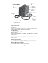
4.3 Main Structure (Refer To Panel Sketch)
1
2
3
45
6
7
8
11 10
9
HD Front Panel Sketch
13
15
14
19
17
18
16
20
21
3 ~
XXX A
IP21S
XX A
XX V
XX KVA
XX A
%60 100
XXX A
XX KVA
XX V
%
2
I
575 V
1
2
1
I
P
U
~ 60 Hz
XX ~ XX V
X
0
1
U
U
3
XX A / XX V ~ XXX A / XX V
HD Back Panel Sketch

Page 8
1. Welding Current Meter 2. Welding Voltage Meter 3. Host Ring 4. Thermal Indicator Light
5. Power Indicator Light 6. Power Voltage Fine Switch 7. Voltage Course Switch 8. Trailing wheel
9. Front wheel 10. Work Piece Connection 11. Work Piece Connection 12. Power Input Cable
13. Hook For Cable 14. Gas bottle protection bracket 15. Nameplate 16. Heater Socket
17. Supply Fuse 18. Wire Feeder Connection 19. Controlling Cable Connection 20. Gas Bottle Rack
1. connection for torch 2. connection for torch 3. front wheel 4. rear wheel
5. handle 6. welding current knob 7. name plate 8. gas check button
9. wire feed button 10. spool shaft 11.2/4 step switch 12. handle
13. Burn back time knob 14. Slow wire feeding switch 15. wire feeder motor 16. Welding cable connector
17.Cable connector 18.Gas connector
4.4.1 2/4 step switch
2 step: Press torch trigger, gas on, power on, wire feeding start.
Release torch trigger, wire feeding stop, gas off, power off.
4 step: Press torch trigger, gas on, power on, wire feeding start.
Release torch trigger, continuous working.
4.4.2 Gas check button
Press, only solenoid works, other circuit close.
4.4.3 Wire feed button
Press, wire feeder motor works, other circuit close.
4.4.4 Welding current knob
Stepless welding current adjustment
4.4.5 Burn back time adjustment
Adjusting burn back time
4.4.6 Slow wire feeding speed knob
Adjusting wire feeding speed before arc generation.
t

Page 9
5. Installation
ATTENTION: The protection class of HD series semi-automatic gas shielded welder is IP21S.
Warning
! The welder must be grounded before using. When several welders or with other electrical
appliances are using a common grounding device, they must be parallel connection, series connection is
forbidden. The welder’s ground cable sectional area should not be less than that of input power cable.
5.1. Placement
* The welder should be located
away from dust, chemical, erodible, inflammable or explosive gas or goods.
* The welder should be installed in the place where it is not exposed to sun and rain. Also it must be stored in
less humid place with the temperature range ﹣10 ~﹢40℃mm.
* There should be at least 50cm space for the welding machine.
5.2 Connection between HD and Power Supply
* Connect “Input Power Cable” on the rear board to three phase power.
* Tighten all connections properly
* Single welder power supply:
Table 3
ITEM
HD-350
Air Switch A 30
Power Cable mm
2
≥ 4
5.3 Connection between HD and Wire Feeder
* Connect quick connector (male) of connecting cable to the socket on the back panel of welding machine,
and twist the quick connector (male) clockwise to ensure the tight connection. Connect other end of
connecting cable with wire feeder, and ensure the tight connection.
* Connect multi-core control cable with welding machine and wire feeder respectively.
5.4 Connection between HD and Gas System
* Gas regulator optional installed and screwed firmly on the bottle to prevent air leak.
* Connect and firmly screw the two core plug of heater cable on the gas regulator to “Heater Socket” on the
rear board of welder.
* Connect the one end of gas hose in the attached accessories with the outlet of gas regulator and firmly hold
with hoop also in the attached accessories, the other end to “Gas Inlet” (gas valve joint) on the back of wire
feeder device.
Earth cable
Welder
Power Cable
3P Power
CO2(or CO2+Ar)
Gas Pipe
Regulator
Multi-core CableWelding CableWire Feeder
Torch
Torch cable
Torch Switch
Work Piece
HD Connecting Sketch

Page 10
5.5 Installation and Connection for Wire Feeder System (See Chart)
* Select suitable wire for the welding job. The wire diameter must be matched with drive roll; wire guide pipe
liner and contact tip (Please Refer to Table 3).
* Open the cover of wire cabinet, put wire spool on the shaft. Attention: Wire end under the wire spool
opposite wire feeder.
* There is damping screw device in the wire spool (hex head screw will be seen when open the cover).Pull the
wire reel with hand when coarsely adjust. If resistance is over large, may adjust damping bolt, screw
clockwise will enlarge, and vice versa. The cover must be screwed firmly after adjustment.
* Feed wire into “Wire Guide Rear” of wire feeder, align wire with roll groove through “Feed Roll”.
5.1.6 Connection between HD and Torch
* Connect torch head with “Torch Socket” on front panel.
5.1.7 Connection between HD and Work Piece
Connect quick connector (male) of earth cable to the socket on the front panel of welding machine, and
twist the quick connector (male) clockwise to ensure the tight connection. The other end clamps work
piece.
6. Operation
Notice: * Cut off power and close valve when finished welding or leave the job site temporary.
* The welding worker should wear protected gear.
* Isolating light screen must be placed around the job site in case of arc light influence.
* Inflammable or explosive materials are prohibited to access the job site.
6.1 Work Piece Cleaning Before Welding
Weld site must be cleaned, no existing rust, greasy dirt, water and paint etc.
6.2 Adjustment and Test before Welding
* The fan will work after connecting.
* Pressure data will be shown after open the valve of CO
2
cylinder.
* Open the valve of gas regulator (rotate clockwise), loose “feed roll”, press torch switch, adjust gas flow to
meet the requirements of technology and then press “feed roll”.
* Press torch switch and feed the wire to torch head.
* The torch cable must be pulled a line in case of wire jam.
* The nozzle and contact tip must be dismantled when testing wire feeding to prevent wire jam at torch head.
* First, please observe the wire whether through the groove of feed roll when wire feeding, if not, adjust.
Second, please observe whether wire feeding speed is even. If not, the reason may be that the pressing roll
is too firm or loose. You should adjust it to assure of even feeding.

Page 11
6.3 Welding
Observe the voltage and current data of welder whether meet to the requirements of welding norm when
test welding (Refer to Table 5). If not, please adjust knob. It does not weld until meet the requirements.
6.4 Welding Norm (For Reference) Table 5
Material
Thickness
mm
Wire
Diameter
mm
Liner Inner
Diameter
mm
Liner
Specifications
mm
Current
A
Voltage
V
Gas Flow
l/min
0.8~1.5 Φ0.8 Φ1.4 1.2×1.6(blue) 50~90 17~18
6
·1.0~2.5 Φ0.8 Φ1.4 1.2×1.6(blue) 60~100 18~19
7
2.5~4.0 Φ0.8 Φ1.4 1.2×1.6(blue) 100~140 21~24
8
·2.0~5.0 Φ1.0 Φ1.6 1.2×1.8(black) 70~120 19~21
9
5.0~10 Φ1.0 Φ1.6 1.2×1.8(black) 120~170 23~26
10
·5.0~8.0 Φ1.2 Φ1.6 1.2×1.8(black) 110~180 22~24
10
8.0~12 Φ1.2 Φ1.6 1.2×1.8(black) 160~300 25~38
12
·10~16 Φ1.6 Φ2.0 1.2×2.2(grey) 140~180 22~24
15
>16 Φ1.6 Φ2.0 1.2×2.2(grey) 180~400 34~40
18
·Are short circuit transition, the others are grain transition.
6.5 Maintenance and Service
* The HD series CO
2
welder is a semi-automatic gas shielded welder. To properly operate & maintain the
welder can assure it of good performance and prolong its operating life. Only the qualified personnel are
allowed to be in charge of repairing. It is strongly recommended customers contact with our company or
agent for technical, repairing, accessories supply and service back-up when they feel unable to work out the
technical hitch or problems.
* Maintenance job should be conducted by the trained personnel.
* If the welder is not in use either for a long time or temporarily, it should be kept dry and have good
ventilation to free it from moisture, eroded or toxic gas. The tolerable temperature ranges from ﹣25 ~﹢
55 , and the relative humidity can not be more than 90%.℃
* Dust removal
The professional maintenance personnel should use dry compressed air (use air compressor or bellows) to
remove the dust inside the machine. The part adhering to grease must be cleaned with cloth while make sure
there are no loose parts ,the machine should be cleaned twice a year.
* Regularly check the input & output cables of welder.
*Don’t pull the feeder device by means of the torch cable.
* Use qualified wire.
* Clean the dust from liner with compressed air regularly (the dust is accumulated by friction between wire
and liner) to assure of even wire feeding.
* Please replace the feed roll if find it wear and tear to prevent wire uneven feeding.
ATTENTION:
* The welder voltage is always higher, so the safety precaution should be taken before repair to avoid
Accidental shock. Under no circumstance can anyone except the professionally trained personnel
open the case of the machine.
* Switch off the power source each time when removing dust.
* No touching inside cable or work piece while removing dust.

Page 12
7. Trouble Shooting
7.1 Trouble Shooting (See Table 6)
Table 6
No. Breakdown Analysis Solutions
Input fuse break down Change fuse
Power isn’t connected Check and turn on power
Torch switch break down Change torch switch
1
Wire won't feed
when press torch
switch
Multi-cored cable failure (Separate type) Close controlling cable
Multi-cored cable failure (Separate type) Close controlling cable
Current adjust potentiometer on wire feeding
device break down
Change potentiometer
Wire feeder cable break down Close wire feeder power
2
Have OCV and
gas but no wire
feeding function
PCB break down Change PCB
Control PCB failure Change control PCB
3
Have wire feeding
and gas sending
function but no
OCV
Controlling coil of AC contactor has no power Connect coil with power supply
Current adjust potentiometer break down Change potentiometer
4
Welding current
maladjustment
PCB has problem Change PCB
Voltage is too low, less than 517V Increase power supply
Power lack phase Connect 3 phase power
5
Low OCV
Main circuit diode break down lead to lacking phase Change main circuit diode
Incorrect welding norm selected, current doesn’t
match with voltage
Adjust welding norm
Contact tip or wire feeding roller doesn’t match
with wire type
Change contact tip or roller
Wire feeding resistance is too large Clean or replace the liner and the torch
cable had better in the line direction.
Power lack phase Connect 3 phase power
6
Arc is not stable
and splash is
large
Main circuit diode break down lead to lacking phase Change main circuit diode
Earth cable break Connect earth cable
7
OCV and wire
feeding are normal
but can not
generate arc
Work piece has much greasy dirty or rusty stain Clean greasy dirty or rusty stain
Gas hose break Connect gas system and bind firmly
Gas hose is pressed or blocked up Check gas system
8
No shielded gas
Solenoid break down Repair or change electromagnetic valve
Contact tip stick with wire Change the nozzle 9
Wire is bent or
even buckling at
the part of roller
and inlet of wire
guide pipe
The inlet of liner is far away from roller of wire
feeding, guide is not good.
Shorten the distance

Page 13
The roller’s level part and wire guide pipe core
are not in a straight line.
Adjust and make them on one direct line
Liner inner diameter is too little or too large Replace liner
Liner block up Clean the liner
10 Others Please contact distributor
8. Circuit Diagram
The circuit chart of HD-350 (Only for reference, no notification will be given if there are any changes.)
V
A

Page 14
9. Complete Set Specifications
Table 10
* HD-350 Semiautomatic Gas Shielded Welder 1 unit
* Wire Feeder 1
* Product Certificate 1
* Warranty Card 1
* Operator’s Manual 1
Accessories
* Torch 1
* Wire Feeder Liner (HD 350) 1
* Gas hose 1
* Earth Cable (clamp) 1
* Welding Cable 1
* Control Cable 1
* Gas Regulator 1
* Mask 1
* Small Parts (2 hoops,contact tip, fuse etc.)

Page 15
10. Transport & Storage
* The series welder is box structure; you can hold the handle or the bottom to move it. The machines should
be firmly fixed during transportation.
* The machines should be free from rain and snow during transportation and storage. Keep notice of the
warning sign on the packing box when load and unload. The warehouse should keep dry & ventilation and
free from corrosive gas or dust. The tolerable temperature ranges from ﹣25 ~﹢55℃ and the relative
humidity can not be more than 90%.
* After the package has been opened, it is suggested to repack the product as per prior requirement for future
storage and transport. (Cleaning job is required before storage and you must seal the plastic bag in the box
for storage.)
* Users should keep the packing materials with the machine to keep well storage during the long
transportation. If the machine need transfer, the wooden case is required. Sign such as ‘Lift’ and ‘Free of
rain’ should be labeled on the case.
11. Spare part list
HD-4 wire feeder

Page 16
NO. CODE ITEM QTY.
1 1.1.01.02.8774 side panel 1
2 2.07.40.317 motor 1
3 1.2.07.03.0315 cable 1
4 2.05.05.952 spool holder 1
5 1.1.01.03.1602 back panel 1
6 2.07.55.006 gas valve 1
7 2.02.20.420 gas contactor 1
8 2.07.54.104 socket 1
9 2.07.57.117 quick contactor 1
10 1.1.03.03.0171 handle 1
11 1.1.04.07.0001 induction welding part 1
12 1.1.01.02.8773 fixed side panel 1
13 2.05.07.313 wheel 2
14 1.1.01.04.0183 wire feeder holder 1
15 2.05.07.314 castor 2
16 1.1.01.03.1601 front panel 1
17 2.07.57.942 4 pin contactor 1
18 2.07.57.942-M mig gun conactor 1
19 2.07.10.043 potentiometer 3
20 2.07.11.009 potentiometer knob-I 1
21 2.07.80.634 button switch 2
22 2.07.80.371 switch 1
23 2.07.57.942-M mig gun conactor 1
24 2.05.06.011 insulation-I 2
25 2.05.06.012 insulation-II 2
26 2.07.51.703 magnet 1
27 2.04.31.109 winding wire 1
28 1.1.01.04.1323 bottom panel 1
29 1.1.01.03.1467 middle panel 1
30 1.1.05.02.0107 PCB 1
31 2.07.11.006 potentiometer knob-II 2
32 2.20.09.852 V Groove wire roller 0.030/0.035 2
33 2.20.09.853 V Groove wire roller 0.040/0.045 2
34 2.20.09.854 V Knurled wire roller 0.035/0.045 2
35 2.20.09.855 V Knurled wire roller 0.055/1-16 2
36 2.07.57.942-G
Guide liner φ4*1.6
1

Page 17
HD-350 WELDER
NO. CODE ITEM QTY.
1 1.1.01.01.0342 top panel 1
2 2.07.25.921 control transformer 1
3 2.07.41.004 AC contactor 1
4 2.05.07.108 wheel 2
5 1.1.01.05.0141 gas cylinder leftside holder 1
6 2.07.89.048 fan 1
7 1.1.01.03.1068 back panel 1
8 2.07.52.019 fuse 1
9 2.07.52.028 fuse holder 1
10 2.07.57.757 socket-I 1
11 1.1.01.05.0144 hanger 1
12 2.07.57.119 quick connector 1
13 1.2.07.01.0124 input cable 1
14 1.1.01.04.0379 gas cylinder holder 1
15 2.04.30.104 fixed cable head 1
16 2.07.54.122 socket-II 1
17 2.01.29.006 hinge 1
18 2.05.01.018 insulation for heat seak 4
19 2.05.01.021 insulation for heat seak 4
20 1.1.02.01.1023 fan holder 2
21 1.1.01.04.0377 panel for holding the fan 1
22 2.06.14.404 nut 2

Page 18
23 1.1.01.02.8642 right panel 1
24 1.1.01.05.0142 gas cylinder rightside holder 1
25 1.1.01.05.0140 axle 1
26 1.1.02.01.0967 axle holder 2
27 1.1.04.03.0105 electric reactor 1
28 1.1.01.04.0376 botton panel 1
29 2.05.07.303 castor 2
30 2.07.80.566 switch-I 1
31 2.07.80.569 switch-II 1
32 1.1.01.03.1069 front panel 1
33 1.2.08.02.0171 grounding cable 1
34 2.07.28.209 diode-I 1
35 2.07.28.211 diode-II 1
36 2.07.46.754 digital ammeter 2
37 1.1.01.05.0138 handle 1
38 2.01.31.061 left holder 1
39 2.01.31.062 right holder 1
40 1.1.02.01.0957 heat seak holder 2
41 2.07.37.551 rectifier bridge 1
42 2.07.42.009 diverter 1
43 1.1.04.01.0105 transformer 1
44 1.1.01.04.0378 middle panel 1
45 1.1.05.04.0010 digital panel 1
46 1.1.01.02.8641 left panel 1
47 2.06.04.010 bolt 2
48 1.2.07.03.0527 connecting cable 1 1
49 1.2.07.03.0447 connecting cable 2 1
50 1.2.07.03.0143 connecting cable 3 1
51 1.2.07.03.1047 connecting cable 4 1
52 1.2.07.03.0460 connecting cable 5 1
53 1.2.07.03.0336 connecting cable 6 1
54 1.2.07.03.0531 connecting cable 7 1
Page is loading ...
/