GE PDW7712N10BB Installation guide
- Category
- Dishwashers
- Type
- Installation guide
This manual is also suitable for

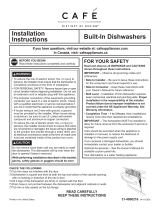
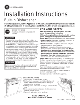
Installation
Instructions
Built-In
Dishwasher
l If you have questions,call 800-GECARESor visit our website at: www.GEAppliances.com I
BEFORE YOU BEGIN
Read these instructions completely and carefully.
•IMPORTANT - C.,se,,'e.Ug,,,'e,',,i,,g
codes and ordinances.
• Note to Installer - Be sure to leave these instruc-
ti(ms for the consumer's and local inspector's use.
• Note to Consumer - Keep these instructions with
your (-)wiper's Manual fi)r fllture retbrei_ce.
• Skill Level - Installation of this dishwasher requires
basic mechanical and electrical skills. Proper installa-
tion is the responsibility of the installer. Product failure
due to improper installation is not covered under the
GE Appliance Waxranty.
• Completion Time - 1 to 3 Hours, New installations
require m ore tim e than replacement installation s.
•IMPORTANT - Thedish,,'.she,MUST_,e
installed to alhm tot fllture remoxal fl'om the enclo-
sure if serxice is required.
If vou receixed a damaged dislmasher, you should
immediateh' contact your dealer or builder.
Optional Accessories - See the o,vne,"s m.n_,.1
fin" axailable custom panel kits.
FOR YOUR SAFETY
Read and observe all CAUTIONS and WARNINGS
shown throughout these instructions. While performing
installations described in this booklet, gloves, safety
glasses or goggles should be worn.
READ CAREFULLY.
KEEP THESE INSTRUCTIONS.

Installation Preparation
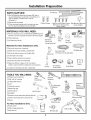
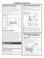
PARTS SUPPLIED:
[] Two#8 Phillips flat head wood screws, 5/8"long to
secure dishwasher to underside of countertop orto
side of cabinetry. (Tapedtotop or side of
dishwasher.)
[] Side and top trim pieces
[] 2 Side mounting brackets with 4 mounting screws
(for non-wood countertops) on some models
2Wood Screws
Trim Pieces
4,#8 Pan head Phillips Screws Side Mounting Brackets
3/8"longfor side mounting (some models)
(somemodels)
MATERIALS YOU WILL NEED :
[] Ferrule,compression nut and 90° Elbow(3/8"NPTexternal
thread on one end,opposite end sizedto fit water supply)
[] Thread sealtape
[] ULListed wire nuts (3)
Materials For New Installations Only:
[] Air gap for drain hose, if required
[] Waste tee for house plumbing,if applicable
[] Electrical cable or power cord, if applicable
[] Screwtype hose clamps
[] Strain relieffor electrical connection.
[] Handshut-off valve (recommended)
[] Water line 3/8"rain.copper or 1/2"rain.plastic
(plastic must betested for temperature and pressure)
[] Couplerfor extending drain line, if applicable
_@ _td__0ff
90° Elbow, Valve Thread
Ferrule and SealTape
Compression Nut
Waste Tee
Electrical Cable
(or Power Cord,if applicable)
Air Gap
Wire Nuts (3)
Hot Water line
Coupler
Screw Type Strain Relief
Hose Clamps
TOOLS YOU WILL NEED:
[] Phillips head screwdriver
[] 5/16"and1/4"nutdriver
[] 6"Adjustable wrench
[] Level
[] Carpenters square
[] Measuring tape
[] Safety glasses
[] Flashlight
[] Bucketto catch water when flushing the line
[] 15/16"socket (optional for skid removal)
[] Gloves
For New Installations Only:
[] Tubingcutter
[] Drill and appropriate bits
[] Hole saw set
Screwdriver
15/16"Socket
Flashlight
Level
and 5/16"
6"Adjustable
Wrench
Nutdriver
TubingCutter
Measuring Tape
Gloves
Bucket
Safety Glasses
Hole SawSet
Carpenters
Square
Drill and Bits
2

Installation Preparation
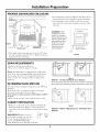
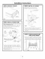
PREPARE DISHWASHER ENCLOSURE
34--I/2"_+I/4"
Undersideof
Counter'[op
toFloor
Figure[_A _//_
ThisWallArea
of
Pipesorwires
24"
Min,
FloorMUSTbeEven
WithRoomFloor.
3abinets
Square
and
Plumb
• The rough cabinet opening must be at lea,'t 24 deep,
24" _i(le and approximately : 4-1/2 high fl'om floor to
underside of the countertop.
• The dishwasher must be installed so that drain hose is
no m ore than 10 tibet in length for proper drainage.
• The dishwasher must be fifllv enclosed on the top,
sides and back, mad must not support may part of the
enclostlre,
CLEARANCES:When
installed into a corner,
allow 2" min. clearance
between dishwasher and
adjacent cabinet, wall or
other appliances. Allow
28-3/8"rain.clearance
from the front ofthe
dishwasher for door
opening. Figure B
I
Countertop
{ - 28-3/8"
FigureB
DRAIN REQUIREMENTS
• Follov, local codes and ordinances.
• Do not exceed 10 ti_et (listance to drain.
Note: This dishwasher is equipped with a high drain
loop. There is no minimum height required for drain
hose routing. Howevei, 18" illinillltllll ti'Olll f]ooi" to
center of waste tee or disposer inlet is reqtfired. See
Figure D.
DETERMINE DRAIN METHOD
The type of drain installation depends on the following
question.
[] Do local codes or ordinances require an air gap?
[] Is waste tee less than 18" above floor?
If the answer to either question is YES, Method 1 MUST
be used.
• If the answers are NO, either method may be used.
CABINET PREPARATION
• Drill a 1-1/2" dia. hole in the cabinet wall within the
shaded areas shown in Figure A fin" the drain hose
connection. The hole should be smooth with no sharp
edges.
IMPORTANT: When connect-
ing drain line to disposei, check to
be sure that drain plug has been
removed. DISH_&SHER WILL
NOT DRAIN IF PLUG IS LEFT IN PLACE,
Remove
Hopper
Plug
FigureC
Method 1 - Air Gap with Waste Tee or Disposer
An air gap must be usedwhen required by local codesand ordinances.
The air gapmust be installed according to manufacturers instructions.
FigureD
Method 2 - Built-in "High Drain Loop" with Waste Tee or
Disposer

Installation Preparation
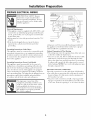
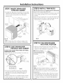
PREPARE ELECTRICAL WIRING
FOR PERSONAL SAFETY: Remove
house fllse or open circuit breaker
before begilming installation. Do not
use an extension cord or adapter phlg
with this appliance.
Electrical Requirements
• This appliance must be supplied with 120V, 60 Hz., and
connected to an individual properly grounded branch
circuit, protected by a 15 or 20 ampere circuit breaker
or time delay fllse.
• Wiring intist be 2 wire with ground and rated tot 75°C
(176°F).
• If tile electrical supply does not meet tile above
requirements, call a licensed electrician before
proceeding.
Gromlding Instructions-Cable Direct
This appliance must be comaected to a grounded metal,
permanent wiring system, or an equipment grounding
conductor must be i'/ln with tile circuit conductors and
be com_ected to tile equipment grounding terminal or
lead on tile appliance.
Grounding Instructions-Power Cord Models
This appliance must be grounded. In tile event of a
malflmction or breakdown, grounding will reduce tile
risk of electric shock by providing a path of least resis-
tance tor electric current. This appliance is equipped
with a cord having an equipment grounding conductor
and a grounding plug. Tile plug must be plugged into an
appropriate outlet that is installed and grounded in
accordance with all local codes and ordinances.
Alternate -_"",
! \
Receptaclet \
Cabinet
FigureE Black
White
with power cord: Do not modit_' tile plug provided with
tile appliance: if it will not fit tile outlet, have a proper
outlet installed bv a qualified technician.
Cabinet Preparation & Wire Routing
• Tile wiring may enter tile opening fl'om either side, rear
or tile floor within tile shaded area.
• Cut a 1-1/2" max. dia. hole to admit tile electrical cable.
Cable direct com_ections may pass through tile same
hole as tile drain hose and hot water line, if convenient.
If cabinet wall is metal, tile hole edge i,/ust be covered
with a bushing. NOTE: Power cords with plug must pass
through a separate hole.
Electrical Connection to Dishwasher
Electrical com_ection is on the right fi'ont of dishwasher.
• For cable direct comlections the cable must be routed as
shown in Figure E. Cable Inust extelld a minimum of
24" fi'om tile rear wall.
• For power cord comaections, install a 3-prong ground-
ing type receptacle in tile sink cabinet rear wall, 6" rain.
or 18" max. fl'om tile opening, 6" to 18" above tile floor.
4

Installation Instructions
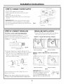
PREPARE HOT WATER LINE
• The line may enter fl'om either side, rear or floor
within the shaded area shown in Figure F.
• The line may pass through the same hole as the
electrical cable and drain hose. Or, cut an additional
1-]/2" dia. hole to accommodate the water line. If
power cord with plug is used, water line must not pass
through power cord hole.
A_ _N
Z [ I \
\
I I \
I I
i I
\
\
4 '_
BB
BB
BB
From
Cabinet
2" From Floor
Cabinet Face
FigureF
Water Line Connection
• Turn off the water supply.
• Install a hand shut-off valve in an accessible location,
such as trader the sink. (Optional, but strongly recom-
mended and may be required by local codes.)
• Water com_ection is orJ the left side of the dishwasher.
Install the hot water inlet line, using no less than 3/8"
O.D. copper tubing. Route the line as shown in Figm'e
F and extend torward at least 19" fl'om rear wall.
• A(!just water heater fin" 190°F to 150°F temperature.
• Flush water line to clean out debris.
• The hot water supply line pressm'e must be 20-120 PSI.
Before You Begin
Locate and set aside the 2 Phillips head cotmtertop
motmting screws wrapped with yelhm tape and stuck to
the top or side of the dislmasher.
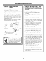
[STEP 1] CHECK DOOR BALANCE
With dishwasher on wood skid, check the door balance
by opening and closing the door.
• If door drops open when released, increase spring
tension. If door closes when released, decrease tension.
Note: Increase or decrease
tension as shown. Adjust
both springs to the same
tension setting to correct
balance.
Increase
Spring
Tension
Decrease
Spring
Tension
Correct
Incorrect
FigureG
TIP: If door spring a(!justment is necessary, check door
opening and closing. If door does not open easily or
thlls too quickl 5 check spring cable routing. The cable is
held in place bv "shoulders" on the pulley. Check to be
sure cable has not slipped over the pulley shoulders.
[STEP 2] REMOVE WOOD BASE,
INSTALL LEVELING LEGS
IMPORTANT - Do not kick off wood base !
Damage will occur.
• Move the dishwasher close to the installation
location and lay it on its back.
• Remove the four leveling legs on the underside of
the wood base with an a(!justable
wrench or l 5/16" socket.
• Discard base.
FigureH
• Screw lex eling legs back into the dislmasher fl'ame,
approximately l / 4" fl'om fl'am e as sh o_xn.

Installation Instructions
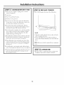
[STEP 3] REMOVE TOEKICK
• Remoxe the mo toekick screws,
Remove2
ToekickScrews
FigureI
[STEP 4] INSTALL POWER CORD
Skip this step if dishwasher will be direct wired or has
a factory installed power cord.
The power cord and com_ections must comply with
the National Electrical Code, Section 422 and/or
local codes and ordinances,
• Maximmn power cord length is 6 teet.
A
Remove
JunctionBox
Cover
StrainBelief _
and Tighten
White
Ground__ __Black
CheckThatWhite, Blackand
GreenDishwasherWires AreThreaded
ThruSreailHob in Bracket
FigureJ
D
UseULListed
WireNuts
• Cormect incoming power cord white (or ribbed) to
dishwasher white, black (or smooth) to black and
grotmd to dishwasher green wire. Use UL listed wire
mlts of appropriate size.
• Replace.jtmction box cover. Be sure wires are not
pinched tamer the cover.
[STEP 5] INSTALL 90 ° ELBOW
• Wrap 90 ° elbow with thread seal tape.
• Install a 90 ° elbow onto the water xalxe.
FrontofDishwasher
90°
Elbow
FigureK
Thread Seal Tape
• Do not over tighten 90 ° elbo_, water valve bracket
could bend or water valve fitting could break.
• Position the end of the elbow to thce the rear of the
dishwasher.
]STEP 6] POSITION WATER LINE
AND HOUSE WIRING
• Position water supply line and house wiring on the
floor of the opening to avoid interterence with base
of dishwasher and components trader dishwasher.
Line Wiring
m
Figurek

Installation Instructions
ISTEP 71 INSERT DRAIN HOSE
THROUGH CABINET
• Upright the dishwasher and position in fl'ont of the
opening. Ii_sert drain hose into cabinet wall hole. If
a power cord is used, guide the end through a
separate hole.
MaximumDrainHose
Length10'
Insulation
Blanket_
Hose
House
Wiring
PowerCord
(if Used)
TIP: Position water line and house wiring on the
floor to moid interference with base of dishxxasher.
[STEP 8] SLIDE DISHWASHER
PARTIALLY INTO CABINET
DO NOT PUSH AGAINST FRONT PANEL WITH KNEES.
DAMAGE WILL OCCUR.
• Slide dislmasher into the opening a tew inches at a
tinle.
30 NotPushAgainst
FrontDoorPanelWith
Knee.Damageto The
DoorPanelWill Occur.
FigureN
• As vou proceed, pull the drain hose through the
opening under the sink. Stop pushing when the
dishwasher is a few inches forward of ac!jacent
cabinetry.
• Make S/li'e drain hose is not kinked under the dish-
washer and there is no interference with the water
line and wiring or any other component.
ISTEP91INSTALL TRIM PIECES
Skip this step if trim is not supplied with the dishwasher,
• Locate trim strips inside dishwasher.
• Press trim onto the tub flange on each side. Start with
the top edge, pressing on as vou move towards the
bottom.
• Press the two top trim pieces on each side of the latch,
• Open and close the door to check that trim does not
bind and does not intertere with door latch.
TrimStrip
Trim_
Strip
Figure0
ISTEP101PUSH DISHWASHER
INTO FINAL POSITION
• Check to be sure that wires are secure under the
dishwasher and not pinched or in contact with door
springs or other dishwasher components.
Rote: If stone eountertops
are used, see Step 12
pushing the dishwasher into
the opening.
Figure P
WaterLine
90° Elbow Water Line
House
"_ Wiring
TIP: Check tub insulation blanket, if equipped. It
should be positioned so it is not "bunched up" or
interfering with door springs. Check by opening and
closing door.
• Push dishwasher into the cabinet. The fl'ont corners
of the dishwasher door should be flush with cabinet
doors. Be carefifl not to dent fl'ont panel with knees
or damage cotmtertop or cabinets with dishwasher
parts.

Installation Instructions
ISTEP 111LEVEL DISHWASHER
IMPORTANT - Dishwasher must be level fl)r proper
dish rack operation and wash pertormance.
• Place level on
door and rack
track inside tile (-
tub as showI1 to
check that the
dishwasher is
level,
FigureQ
• Lexel tile dish- ]
x_asher bya(!justing L AccessHob
the It)ill" leveling
legs individually.
• If a(!justment to tile
right rear leveling
leg is required,
loosen jm_ction box
bracket screw
(through tile access
hole) and rotate FigureR
bracket clockwise,
TIP: Pull lower rack out, about halflvay. Check to be
sure tile rack does not roll fl)rward or back into dish-
washer. If tile rack rolls either direction, tile dishwasher
must be leveled again.
• If door hits tub, tile dishwasher is not installed
correctl> At{just leveling legs to align door to tub.
ISTEP 12 1POSITION DISHWASHER, SECURE TO CABINET
Tile dishwasher must be secm'ed to tile co/mtertop or
tile cabinet sides. When co/mtertops are made of wood,
use Method 1. Some models are supplied with side
mounting brackets fl)r use when cotmtertops are granite
or other materials that will not accept screws, [.lse
Method 2 to secm'e dishwasher at the sides.
• Fasten a side too/rating bracket to each side of tile tub
with tile #8 pan head screws pro_,ided.
Side
Mounting
Brackets
Method 1
Secure dishwasher to wood countertop
• Position dishwasher so that tile door lines up with tile
fl'ont thce of a(!jacent cabinet.
Brackets WoodCountertop
FigureS
IMPORTANT: Check to be sm'e tile dishwasher is
centered in tile opening and there is no interference
with ac!jacent cabinets when opening ,11"closing tile door.
• Fasten tile dishwasher to tile ,mderside of tile co/rater-
top with tile 2 Phillips screws provided.
Method 2
For Models supplied with side mounting brackets
• Pull dishwasher out oI tile opening just enough to
access tile tub fl'ame.
Tub Frame
FigureT
Install
EachSide
Brackets
• Position dishwasher so that tile door lines up with tile
fl'ont thce of a(!jacent cabinet.
IMPORTANT: Check to be sure tile dishwasher is
centered in tile opening and there is no interterence
with ac!jacent cabinets when opening or closing tile door.
StoneCountertop
/
/
FigureU ///// "% SideBrackets
/////
• Fasten tile brackets to cabinet sides using tile 2
Phillips head co/mtertop screws.
IMPORTANT: Drive screws straight and flush. Protrud-
ing screw heads will scratch the top or sides of tile
control panel and can intertere with door closing.
8

Installation Instructions
[STEP 13 1CONNECT WATER SUPPLY
Com_ect water supply line to 90 ° elbow.
• Slide compression inK, then terrule over end of
water line.
• Insert water line into 90 ° elbow.
• Slide ferrule against elbow and secure with compres-
sion mm
IMPORTANT: Check to be sm'e that door spring
does not rub or contact the fill hose or _ater supply
line. Test by opening and closing the door. Re-route the
lines if necessary.
Figure V
/ go° Elbow
DoorSpring
ISTEP 141 CONNECT DRAIN LINE
FOLLOW ALL LOCAL CODES AND ORDINANCES.
The drain hose molded end will fit 5/8", 3/4" or 1"
diameter com_ections on the air gap, waste tee or
disposer. Cut on the marked line as required ti)r yore"
installation. Cutting Lines
IMPORTANT:Donot cutcorrugated FigureW
portionof bose
• Ifa hmger drain hose is required, add up to 42" of
length fi)r a total of 10 fl, length to the thctorv installed
hose, Use 5/8" or 7/8" inside diameter hose and a
coupler to com_ect the two hose ends, Secure the
com_ection with hose clamps,
/
Hose Clamp
Coupler
Hose Clamp
FigureX
• Secm'e the drain hose to the air gap, waste tee or
disposer with clamps.
Note: TOTAL DRAIN HOSE LENGTH MUST NOT
EXCEED 10 FEET FOR PROPER DRAIN OPERATION.
DRAIN LINE INSTALLATION
• Com_ect drain line to air gap, _aste tee or disposer
using either prexiously determined method.
Method 1 - Air gap with waste tee or disposer
Waste Tee Installation Disposer Installation
Figuref
Method 2 - Built-in "High drain loop" with waste tee or
disposer
Waste Tee Installation
Disposer Installation
FigureZ
IMPORTANT: When com_ecting
drain line to disposeI; check to be
stlre that drain plug has been
removed. DISHWASHER WILL NOT
DRAIN IF PLUG IS LEKF IN PLACE.
4--- Remove
Hopper
Plug
9

Installation Instructions
ISTEP151CONNECT POWER
SUPPLY
Skip this step if equipped with power cord
Verify that power is turned off at the source,
(If a power ford with phlg is used, proceed t(> Step 16.)
• Relllove.jtlnctioi_ box covei'.
• Secure house wiring to the back of thejulacti(m box
with a strain relief.
• Locate the three dishwasher wires, (white, black and
green) with stripped ends. Insert dishwasher wires
through the small hole in thejuiaction box. Use wire
nuts t() coimect iiac()ming ground to green, white t()
white and black t() black.
• Replace junction box covei'. Check to be S/li'e that
wires are not pinched under the cover.
A C
Remove Insert Power
Junction Box Cord Wires Thr
Cover Strain Relief
__ andTighten White
Gr°und_d__ ,//Black
B Check That White, Black and -_ J
Green Dishwasher Wires Are Threaded
Thru Small Hole in Bracket [}
Use UL Listed
FigureAA Wire Nuts
[STEP 16] PRE-TEST CHECK LIST
Review this list after installing your dishwasher to
avoid charges for a service call that is not covered by
your warranty,
[] Check to be sure power is OFK
[] Open door and remove all flmm and paper
packaging.
[] Locate tile Owner's Manual in tile literature
package.
[] Read tile Owner's Manual fin" operating
in structions.
[] Check door opei_ing and closing. If door does not
open and close fl'eelv or tends to tall, check spring
cable routing. See Step 1.
[] Check to be sure that wiring is secure under tile
dishwasher, not pinched or in c/intact with door
springs or other components. See Step 10.
[] Check door aligmnent with till). If door hits till),
level dishwasher. See Step 11.
[] Pull lower rack out, about halfway. Check to be
sure it does not roll back or fl)rward on the door. If
the rack moves, at!just leveling legs. See Step 11.
[] Check door aligmn ent with cabinet. If door hits
cabinet, reposition dishwasher. See Step 12.
[] Check that door spring does not contact water line,
fill hose, wiring or other colnpoi1ents. See Step 13.
[] Verify' water supply and drain lines are not kinked
or in contact with other compoi_ents. Contact with
motor or dishwasher fl'ame could cause noise.
[] Turn on tile sink hot water t, ulcet and verify' water
temperature, h_coming water temperature must be
between 120°F and 150°F. 120°F rain. temperature
is req uired fk)r best wash perfk_rmance. See "Pre-
pare Hot Water Line," page 4.
[] Add 2 quarts of water to tile bottom of tile
dishwasher to hlbricate the pump seal.
[] Turn on water supply. Check fin" leaks. Tighten
coimections if needed.
[] Remove protective fihn if present from tile control
panel and door.
10

Installation Instructions
ISTEP 171 DISHWASHER WET TEST
[] Turn on power supply (or plug power cord into
outlet, if equipped).
[] Latch door.
[] Push "Norn_al Wash" button.
[] Push start/reset pad once.
[] Check to be sure that water enters the dishwasher.
If water does not enter the dishwasher, check to be
sure that water and power is turned on.
[] Gheck fin" leaks under the dishwasher. If leak is
I"otlil(l, ttliTl power supply off. then tighten connec-
tions. Restore power after leak is corrected.
[] Gheck for leaks around the door. A leak around the
door could be caused by door rubbing or hitting
against ac!jacent cabinetry. Reposition the dish-
washer if necessary. See Step 19
[] The dishwasher will drain about 5 minutes after the
first fill. Check drain lines. If leaks are t0und, turn
power off. correct as necessary. See Step 14.
[] Open dishwasher door and make sure most of the
water has drained. If not, check that disposer plug
has been ren/oved and/or air gap is not phlgged.
See Step 14.
[] Let dishwasher run through another fill and drain
cycle. Check again fiw leaks and correct as req tfired.
[] At the end of the second drain, push the start/reset
pad once. Wait _'0r dishwasher to pump out and
then unlatch the door.
[STEP 18] REPLACE TOEKICK
• Place toeki('k against the legs ol the dish_asher.
FigureBB
• Align the toekick with the bottom edge and make
sure it is against the floor.
• Insert and tighten the two toekick attachment
screws. The toekick should stay in contact with the
_]oor,
TIP: Make sure toekick is against floor to minimize
noise.
lSTEP 191LITERATURE
• Be sure to leaxe complete literature package and
installation instructions with the consumer.
11

SPECIFICATIONSSUBJECTTOCHANGEWITHOUTNOTICE
_No.31-30530
•No.20601559P070|
(N.D.212) 6/01
-
 1
1
-
 2
2
-
 3
3
-
 4
4
-
 5
5
-
 6
6
-
 7
7
-
 8
8
-
 9
9
-
 10
10
-
 11
11
-
 12
12


GE PDW7712N10BB Installation guide
- Category
- Dishwashers
- Type
- Installation guide
- This manual is also suitable for
Ask a question and I''ll find the answer in the document
Finding information in a document is now easier with AI
Related papers
-
GE Profile PDT775SYNFS Installation guide
-
GE Profile GDP645SYNFS Installation guide
-
GE CDT875P4NW2 Installation guide
-
-
GE Appliances GDT655SSJSS Installation guide
-
Yes 1067685 Installation guide
-
GE ZDT915SPJSS Installation guide
-
-
-
GE ZDT985SPNSS Installation guide
Other documents
-
 Cafe CDT875P4NW2 Installation guide
-
Yes CDT845M5NS5 Installation guide
-
GE Appliances Built-In Dishwashers User manual
-
GE Profile PDT845SMJES Installation View
-
Sunpentown SD6502W Installation guide
-
 Cafe CDT835SSJSS GE Installation Instructions
-
SPT SD-6501W Installation guide
-
 Brama 1500860 Installation guide
-
 Thor Kitchen HDW2401SS Installation guide
-
Electrolux EIDW1805KS Installation guide


