Mattel Ford F150 User manual
- Category
- Toys & accessories
- Type
- User manual
This manual is also suitable for

Owner's Manual
with Assembly Instructions
For Model C3493
Please read this manual and save it with your original sales receipt.
Tools needed for assembly: Phillips Screwdriver and Hammer (not included).
Use only with a Power Wheels
®
6 Volt Rechargeable Battery with A Style Connector
and Built-In Thermal Fuse and Power Wheels
®
Super 6 Volt Charger (both included).
www.powerwheels.com
Ford F-150 and associated trademarks are
used under license from Ford Motor Company.

A Important Information . . . . . . . . . . . . . . . . . . . . . . . . . . . . . . . . . . . . . . . . . . . . . . . . . . . . . . . . . . . . . . . . . . . . .2
B Warnings and Cautions . . . . . . . . . . . . . . . . . . . . . . . . . . . . . . . . . . . . . . . . . . . . . . . . . . . . . . . . . . . . . . . . . . . .3
C Parts . . . . . . . . . . . . . . . . . . . . . . . . . . . . . . . . . . . . . . . . . . . . . . . . . . . . . . . . . . . . . . . . . . . . . . . . . . . . . . . . .4
D Parts Diagram . . . . . . . . . . . . . . . . . . . . . . . . . . . . . . . . . . . . . . . . . . . . . . . . . . . . . . . . . . . . . . . . . . . . . . . . . . .6
E Battery Charging . . . . . . . . . . . . . . . . . . . . . . . . . . . . . . . . . . . . . . . . . . . . . . . . . . . . . . . . . . . . . . . . . . . . . . . . .7
F Assembly . . . . . . . . . . . . . . . . . . . . . . . . . . . . . . . . . . . . . . . . . . . . . . . . . . . . . . . . . . . . . . . . . . . . . . . . . . . . . .9
G Label Decoration . . . . . . . . . . . . . . . . . . . . . . . . . . . . . . . . . . . . . . . . . . . . . . . . . . . . . . . . . . . . . . . . . . . . . . . .18
H Battery Installation . . . . . . . . . . . . . . . . . . . . . . . . . . . . . . . . . . . . . . . . . . . . . . . . . . . . . . . . . . . . . . . . . . . . . .20
I Battery Care and Disposal . . . . . . . . . . . . . . . . . . . . . . . . . . . . . . . . . . . . . . . . . . . . . . . . . . . . . . . . . . . . . . . .21
J Rules for Safe Driving . . . . . . . . . . . . . . . . . . . . . . . . . . . . . . . . . . . . . . . . . . . . . . . . . . . . . . . . . . . . . . . . . . . .22
K How to Operate Your Vehicle . . . . . . . . . . . . . . . . . . . . . . . . . . . . . . . . . . . . . . . . . . . . . . . . . . . . . . . . . . . . . .23
L Caring for Your Vehicle . . . . . . . . . . . . . . . . . . . . . . . . . . . . . . . . . . . . . . . . . . . . . . . . . . . . . . . . . . . . . . . . . . .23
M Limited Warranty . . . . . . . . . . . . . . . . . . . . . . . . . . . . . . . . . . . . . . . . . . . . . . . . . . . . . . . . . . . . . . . . . . . . . . . .24
N Problems and Solutions Guide . . . . . . . . . . . . . . . . . . . . . . . . . . . . . . . . . . . . . . . . . . . . . . . . . . . . . . . . . . . . .25
• Your new vehicle requires adult assembly. Please set
aside at least 60 minutes for assembly.
• You must charge your battery for 18 - 30 hours
before you use your vehicle for the first time. We
recommend that you start charging your battery before
beginning assembly. Please see Battery Charging
beginning on page 7 for detailed instructions.
• Read this manual carefully for important safety
information and operating instructions before using
your vehicle. Keep these instructions for future
reference as they contain important information.
• This vehicle is designed for use on: concrete, asphalt
or other hard surfaces; on generally level terrain; by
children 2-6 years of age.
• Make sure children know and follow these rules for safe
driving and riding:
- always sit in the seat.
- always wear shoes.
- only one (1) rider at a time.
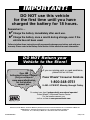
• Use this vehicle ONLY outdoors. Most interior floor-
ing can be damaged by riding this vehicle indoors.
Fisher-Price
®
will not be responsible for damage to
the floor if the vehicle is used indoors.
• To prevent damaging the motors and gears, do not tow
anything behind the vehicle or overload it. Do not exceed
the maximum weight capacity of 65 lbs. (29.5 kg).
• If you have any questions about your Power Wheels
®
vehicle, please call our toll-free service lines at
1-800-348-0751 from 8 AM to 6 PM (EST) Monday
through Friday. Trained customer service representatives
are available to take your call in English or French.
Habla Español? Si usted tiene alguna pregunta ó
necesita asistencia llame gratis 1-800-348-0755 para
los Estados Unidos. Tenemos representantes que
hablan español para atender su llamada.
• For your convenience, Power Wheels
®
maintains an
independently owned and operated Authorized Service
Center Network with more than 400 authorized service
centers nationwide. The authorized service centers will
repair or replace parts under warranty at no extra charge,
and can perform non-warranty repairs for a minimal
charge. To find the authorized service center nearest to
you, visit us on-line at www.powerwheels.com or call
1-800-348-0751.
• If you would like to register your vehicle, please visit us
on-line at www.powerwheels.com.
Table of Contents
Important Information
A
2

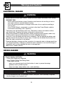
CAUTION
WARNING
WARNING
• Battery can fall out and injure a child if vehicle tips over. Always use battery cover (clamp).
• PREVENT FIRE
- Never modify the electrical system. Alterations could cause a fire resulting in serious
injury and could also ruin the electrical system.
- Use of the wrong type battery or charger could cause a fire or explosion resulting in
serious injury.
- Use of Power Wheels
®
components in products other than Power Wheels
®
vehicles
could cause overheating, fire or explosion.
• The battery must be handled by adults only. The battery is heavy and contains sulfuric
acid (electrolyte). Dropping the battery could result in serious injury.
• Never allow children to charge the battery. Battery charging must be done by adults only.
A child could be injured by the electricity involved in charging the battery.
• Never lift or carry the battery by the wires or connector. This can damage the battery and
possibly cause a fire resulting in serious injury. Lift and carry the battery by the case only.
• Read the safety instructions on the battery.
• Examine the battery, charger and their connectors for excessive wear or damage each time
you charge the battery. If damage or excessive wear is detected, do not use the charger or
the battery until you have replaced the worn or damaged part.
• HOT motors. Handle carefully.
• In the unassembled state, this package contains small parts. Adult assembly is required.
• Use the charger in dry locations only.
• Prevent Injuries and Deaths
• Direct Adult Supervision Required
• Keep Children Within Safe Riding Areas.
These areas must be:
- away from swimming pools and other bodies of water to prevent drownings
- generally level to prevent tipovers
- away from steps, steep inclines, cars, roads and alleys.
RIDING HAZARD
ELECTRICAL HAZARD
Warnings and Cautions
B
3

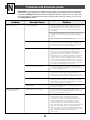
• If you experience a problem with this product, or are missing a part, please call us at 1-800-348-0751, rather than
return this product to the store.
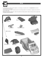
• Please identify all parts before assembly and save all packaging material until assembly is complete to ensure that no
parts are discarded.
• Metal parts have been coated with a lubricant to protect them during shipment. Wipe all metal parts with a paper towel
to remove any excess lubricant.
Parts
C
Brushguard
Tonneau
Steering Linkage Cover
Seat
Steering Wheel Cover
Steering Wheel
Steering Column
Pretend Motor
Side Window – 2
Windshield
Wheel – 4
Vehicle
Hood
4

3
/
16
" Washer - 2
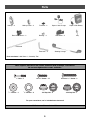
Note: Tighten and loosen all screws and bolts with a Phillips screwdriver.
Do not over-tighten the screws and bolts.
All Fasteners Shown Actual Size
#12-32 x 1
1
/
4
" Screw - 2
#8 x
3
/
4
" Screw - 17
1" Bolt - 2
For your convenience, we’ve included extra fasteners!
.437 Cap Nut - 6
.437"
.354 Cap Nut - 1
.354"
7
/
16
" Washer - 4
Parts
Hubcap – 4
Side Mirror – 2
Fastener – 2
Super 6 Volt Battery
Super 6 Volt Charger
Rear Wheel Driver – 2
Bushing – 2
Hubcap Cover – 4
Parts not shown: Label Sheet - 2, Assembly Tool
Steering Linkage
5
Key
Rear Axle
Front Axle – 2

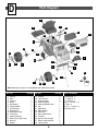
Parts Diagram
D
1
2
3
4
5
6
7
8
9
10
12
11
13
24
14
14
15
15
16
16
28
18
19
20
22
23
26
21
17
17
1 Vehicle 1
2 Seat 1
3 Tonneau 1
4 Hood 1
5 Windshield 1
6 Pretend Motor 1
7 6 Volt Battery 1
8 Brushguard 1
9 Steering Linkage 1
10 Front Axle 2
11 Steering Column 1
12 Steering Linkage Cover 1
13 Bushing 2
14 Wheel 4
No. Part Quantity
Parts Not Shown
15 Hubcap 4
16 .437 Cap Nut 6
17 Hubcap Cover 4
18 Steering Wheel 1
19 Steering Wheel Cover 1
20 Key 1
21 Side Mirror 2
22 Side Window 2
23 Rear Axle 1
24 Rear Wheel Driver 2
25 Fastener 2
26 Super 6 Volt Charger 1
27 Motor (Inside Vehicle) 2
28 .354 Cap Nut 1
Label Sheet - 2
7
/
16
" Washer - 4
3
/
16
" Washer - 2
#8 x
3
/
4
" Screws - 17
1" Bolt - 2
#12 x 1
1
/
4
" Screw - 2
Assembly Tool
No. Part Quantity
Note: Some parts shown are assembled to both sides of the vehicle.
6
25
27
16
16

CAUTION
Use the charger in dry locations only.
WARNING
About Thermal Fuses
Your Power Wheels
®
6 volt battery is equipped with a
built-in thermal fuse. The thermal fuse is a self-resetting
safety device which automatically “trips” and shuts down
operation of the vehicle if the vehicle is overloaded or the
driving conditions too severe. Once a fuse has “tripped”,
it will automatically reset itself after approximately
25 seconds and allow the vehicle to resume normal
operations. To avoid repeated automatic shutdowns,
do not overload the vehicle by exceeding the 65 lb.
(29.5 kg) maximum weight capacity or by towing
anything behind the vehicle. Avoid severe driving
conditions, such as driving up very steep slopes or
running into fixed objects, which can cause the wheels
to stop spinning while power is still being supplied to
the motors.
If a thermal fuse in a battery continually trips under
normal driving conditions, please contact your local
Power Wheels
®
Authorized Service Center. For the
location of the Authorized Service Center nearest to
you, please visit us on-line at www.powerwheels.com
or call 1-800-348-0751.
Important Notes
• Your new battery must be charged for at least 18 hours
before you use it in your vehicle for the first time.
• You do not need to remove the battery from your
vehicle to recharge it.
• The battery must be upright while charging.
• The charger is not a toy.
• Do not short circuit the battery.
• We recommend that you start charging your battery
before beginning assembly of your new vehicle.
• Before charging the battery, examine the battery case
for cracks and other damage which may cause sulfuric
acid (electrolyte) to leak during the charging process.
If damage is detected, do not charge the battery or
use it in your vehicle. Battery acid is very corrosive and
can cause severe damage to surfaces it contacts.
• Do not charge the battery on a surface which could be
damaged by the acid contained inside the battery. Take
precautions to protect the surface on which you charge
your battery.
• Use only a Power Wheels
®
6 volt charger with type
A connector (120 VAC 60 Hz 15W with an output of
6 VDC 1200mA) to charge your Power Wheels
®
rechargeable 6 volt battery.
• If your battery is old and will not accept a charge, do not
leave it in the vehicle. Always remove a dead battery
from the vehicle.
• Battery can fall out and injure a
child if vehicle tips over. Always use
battery cover (clamp).
• PREVENT FIRE
- Never modify the electrical system.
Alterations could cause a fire resulting
in serious injury and could also ruin the
electrical system.
- Use of the wrong type battery or
charger could cause a fire or explosion
resulting in serious injury.
- Use of Power Wheels
®
components in
products other than Power Wheels
®
vehicles could cause overheating,
fire or explosion.
• The battery must be handled by adults
only. The battery is heavy and contains
sulfuric acid (electrolyte). Dropping the
battery could result in serious injury.
• Never allow children to charge the battery.
Battery charging must be done by adults
only. A child could be injured by the
electricity involved in charging the battery.
• Never lift or carry the battery by the wires
or connector. This can damage the battery
and possibly cause a fire resulting in
serious injury. Lift and carry the battery
by the case only.
• Read the safety instructions on
the battery.
• Examine the battery, charger and their
connectors for excessive wear or damage
each time you charge the battery. If
damage or excessive wear is detected, do
not use the charger or the battery until you
have replaced the worn or damaged part.
ELECTRICAL HAZARD
Battery Charging
E
7

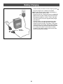
• Insert the battery connector into the charger connector .
• Plug the charger into a standard wall outlet .
Note: If power flow to the wall outlet is controlled by a
switch, make sure the switch is “ON”.
• Before first-time use, charge the battery for at least 18
hours. Never charge the battery longer than 30 hours.
• Recharge the battery for at least 14 hours after each
use of your vehicle. Do not charge the battery longer
than 30 hours.
• Once the battery is charged, disconnect the battery
connector from the charger connector. Unplug the
charger from the wall outlet. The battery is now ready
to be installed in your vehicle. Please see the Battery
Installation section on page 20 for detailed instructions
on installing your battery. If your battery is already
installed in your vehicle, simply re-connect the motor
harness connector to the battery.
11
2
11
1
Charger
Connector
11
2
Battery Charging
8
11
1
Battery
Connector

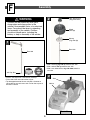
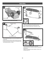
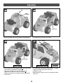
• Rotate the seat back and lift to remove from the vehicle.
3
• Slide a hubcap, peg side up, onto the rear axle.
• Slide a wheel, ribs up, onto the rear axle.
• Slide a rear wheel driver, ring side down, onto the
rear axle.
2
Rear Wheel Driver
(Ring Side Down)
Wheel
(Ribs Up)
Hubcap
(Peg Side Up)
Seat
Vehicle
Rear Axle
Front View
WARNING
Children can be harmed by small parts,
sharp edges and sharp points in the
vehicle’s unassembled state, or by electrical
items. Care should be taken in unpacking
and assembly of the vehicle. Children
should not handle parts, including the
battery, or help in assembly of the vehicle.
Assembly
F
1
Rear Axle
.437 Cap Nut
• Place a .437 cap nut on a flat surface, inside up.
• Fit the end of the rear axle into the cap nut.
• Tap the opposite end of the rear axle with a hammer to
secure the cap nut on the rear axle. Pull on the cap nut to
be sure it’s secure.
.437"
9

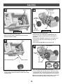
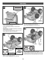
• Position the vehicle upside-down.
• Slide the other rear wheel driver, ring side out, onto
the rear axle. Make sure the driver fits onto the pins in
the motor.
• Slide a wheel, rib side in, onto the rear axle. Make sure
the ribs on the wheel fit into the grooves on the rear
wheel driver.
• Slide a hubcap, peg side in, onto the rear axle.
6
• Fit a .437 cap nut on the end of the rear axle.
• Fit the assembly tool over the cap nut. Tap the end of the
assembly tool with a hammer to secure the cap nut on the
end of the rear axle. Pull the wheel to be sure it is secure.
Hint: You may need the help of another adult to support the
other end of the rear axle while you tap the cap nut.
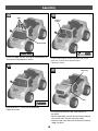
7
• Slide the rear axle assembly through the hole in one
motor, the back end of the vehicle and then out through
the other motor.
5
Assembly
Rear Wheel Driver
(Ring Side Out)
Rear Axle
Wheel
(Rib Side In)
Motor
.437 Cap Nut
Assembly
Tool
Rear Axle
10
Rear Axle Assembly
.437"
Motor
Hole in Motor
Bottom View
Hubcap
(Peg Side In)
• Locate the motors inside the vehicle.
• Make sure each motor is positioned in the rectangular
recesses inside the vehicle.
4
Motors
Top View

Assembly
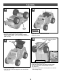
• Turn the steering linkage so that the inside (grooved side)
is facing up.
• Position each front axle so that the short end is facing up.
• Insert the short end of the front axles up through the ends
of the steering linkage, as shown.
Front Axle Short End
Steering Linkage
• Slide a
7
/
16
" washer onto the short end of each front axle.
• Fit the steering linkage cover onto the front axles.
Note: The steering linkage cover should still face you.
Front
Axle
Front
Axle
Steering
Linkage
Cover
7
/
16
"
Washer
7
/
16
"
Washer
• Fit a .437 cap nut onto the end of a front axle.
• Tap the cap nut with a hammer to secure it to the end of
the front axle.
• Repeat this procedure to fasten another .437 cap nut to
the other front axle.
Front Axle
.437
Cap
Nut
11
11
9
10
.437"
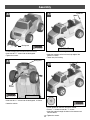
• Fit and snap a hubcap cover to each hubcap.
8
Hubcap Cover
Hubcap Cover

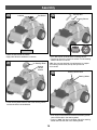
• Fit a wheel, rib side in, onto the front axle.
• Slide a hubcap, peg side in, onto the front axle.
• Slide a
7
/
16
" washer onto a front axle.
• Slide a bushing, ring side first, onto a front axle.
• Fit a .437 cap nut on the end of the front axle.
• Fit the assembly tool over the cap nut. Tap the end of the
assembly tool with a hammer to secure the cap nut on the
end of the front axle. Pull the wheel to be sure it is secure.
13
15
14
Assembly
7
/
16
" Washer
Front Axle
Hubcap
(Peg Side In)
Wheel
(Rib Side In)
12
Front Axle
.437 Cap Nut
Assembly
Tool
Ring Side First
Bushing
Bottom View
Bushing
(Ring Side First)
Front Axle
.437"
• Turn the vehicle so that the front end is toward you.
• Lift the front end of the vehicle.
• Fit the steering linkage assembly to the front end of
the vehicle.
• Insert two #12 x 1
1
/
4
" screws into the holes in the steering
linkage. Tighten the screws.
• Pull the steering linkage to be sure it is secure. If it is not
secure, tighten the screws a few more turns.
12
Steering Linkage
Assembly
Bottom View

• Turn the vehicle upright.
• Insert the tabs on the front edge of the seat into the floor
of the vehicle.
Assembly
13
17
19
• Lift the front end of the vehicle.
• Insert the straight end of the steering column through
the hole in the vehicle and out through the hole in
the dashboard.
• Hook the curved end of the steering column into the hole
in the steering linkage.
Tabs
Seat
Straight End of Steering Column
Hole
Curved
End
Steering
Linkage
Hole
Bottom View
• Insert four #8 x
3
/
4
" screws into the seat.
• Tighten the screws.
18
• Fit and snap a hubcap cover to the hubcap.
• Repeat Assembly steps 13-16 to assemble a washer,
bushing, wheel, hubcap, cap nut and hubcap cover to the
other front axle.
16
Hubcap
Cover

Assembly
14
22
• At an angle, fit the tabs on one side of the steering wheel
cover into the slots in the steering wheel.
• Press to “snap” the tabs on the other side of the steering
wheel cover into the slots in the steering wheel.
23
• Fit a .354 cap nut on the end of the steering column.
• Tap the cap nut with a hammer to secure. Pull the steering
wheel to be sure it it secure.
Hint: You may want the help of another person to support
the steering column while you tap the cap nut with
the hammer.
.354 Cap Nut
Steering Column
Steering Wheel Cover
Steering Wheel
.354"
21
Steering Wheel
Steering
Wheel
Column
• Fit the steering wheel onto the end of the steering column
and into the hole in the dashboard.
• Lower the front end of the vehicle.
• Apply label #8 to the dashboard, as shown.
EF
20
Dashboard
Label #8
Back View

• Fit a side mirror to the side of the vehicle.
26
• From the inside of the vehicle, insert two #8 x
3
/
4
" screws
through the vehicle and into the side mirror.
• Tighten the screws.
• Repeat Assembly steps 26 and 27 to assemble the other
side mirror.
27
Assembly
Side Mirror
15
Right Side View
#8 x
3
/
4
" Screws
25
• First insert the tabs on the bottom edge of the side window
into the slots on the side of the vehicle .
• Then, push to “snap” the tabs at the top of the side
window into the slots in the side of the vehicle .
• Repeat this procedure to assemble the other side window
to the vehicle.
Side Window
Front View
A
B
A
B
24
Key
Hole in
Dashboard
• Insert and “snap” the key into the hole in the dashboard.

• Fit the pretend engine into the front end of the vehicle.
• Insert two 1" bolts into the pretend engine.
• Tighten the screws.
30
• Fit a peg on the hood into a slot in the front end of
the vehicle.
• Flex the hood slightly and then insert the other hood peg
into the other slot in the front end of the vehicle.
• Lower the hood. Push down near the front of the hood to
“snap” into place.
31
Assembly
Pretend
Engine
Hood Peg
Slot
16
• Insert three #8 x
3
/
4
" screws into the windshield.
• Tighten the screws.
29
• Insert and “snap” the tabs at the top of the windshield into
the slots in the top edge of the vehicle.
28
Slots
Windshield
Front View

34
• Peel and remove the backing from the fasteners.
• Apply the fasteners to the back end, top edge of the
vehicle, as shown.
• Throw away the backing.
Assembly
17
Fasteners
Left Side View
• Lift the front end of the vehicle.
• Insert two #8 x
3
/
4
" screws into the brushguard, as shown.
• Lower the vehicle.
33
Brushguard
Bottom View
#8 x
3
/
4
"
Screws
• Fit the brushguard to the front end of the vehicle.
• Insert two #8 x
3
/
4
" screws into the brushguard.
• Tighten the screws.
32
Brushguard
35
Tonneau
• Fit the tonneau on the back end of the vehicle.
• Place a
3
/
16
" washer on two #8 x
3
/
4
" screws.
• Insert the screws through the holes in the tonneau and
into the vehicle.
• Tighten the screws.

Proper label application will help to keep the labels looking their best! When applying labels, keep the following
guidelines in mind:
• Wash your hands before applying the labels.
• Before applying the labels, wipe the surface of the vehicle with a clean, dry cloth to remove any dust or oils.
• Place the labels exactly as shown in the illustrations.
• For best results, avoid repositioning a label once it has been applied to the vehicle.
• After applying a label, rub the label firmly with a clean, dry cloth to make sure the label is adhered to your
vehicle. Start at the center of a label, and smooth towards the outer edges to remove air bubbles.
Front View
Label Decoration
G
18
20
23
26
29
25
21
22
27
28
18
19
9
9
17
2
3
6
7
14
12

Back View
Label Decoration
19
31
4
5
12
13
30
15
16
11
24
1
9
9
19
10

IMPORTANT! Use only a Power Wheels
®
6 volt battery.
Use of any other battery will damage your vehicle. Make
sure that you charge the battery for at least 18 hours
using the enclosed Power Wheels
®
6 volt charger before
operating your vehicle for the first time. Charge the battery
for at least 14 hours after each use of the vehicle. Never
charge the battery longer than 30 hours. Failure to follow
these instructions may damage your battery and will void
your warranty.
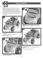
• Plug the motor harness connector into the 6 volt battery.
Push firmly to make sure the connector is inserted
properly.
• Push the battery clamp and fit the battery into the pocket.
• Release the battery clamp.
2
3
4
Motor Harness
Connector
Battery Installation
H
20
Battery Clamp
Battery
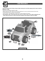
• Grasp the bottom edge of the grill.
• Lift the hood.
• Remove the two screws in the pretend motor.
• Remove the pretend motor.
1
Pretend Motor
• Replace the pretend motor.
• Replace the two #8 x
3
/
4
" screws into the pretend motor
and tighten.
• Lower the hood and “snap” in place.
Pretend Motor
Page is loading ...
Page is loading ...
Page is loading ...
Page is loading ...
Page is loading ...
Page is loading ...
Page is loading ...
Page is loading ...
-
 1
1
-
 2
2
-
 3
3
-
 4
4
-
 5
5
-
 6
6
-
 7
7
-
 8
8
-
 9
9
-
 10
10
-
 11
11
-
 12
12
-
 13
13
-
 14
14
-
 15
15
-
 16
16
-
 17
17
-
 18
18
-
 19
19
-
 20
20
-
 21
21
-
 22
22
-
 23
23
-
 24
24
-
 25
25
-
 26
26
-
 27
27
-
 28
28


Mattel Ford F150 User manual
- Category
- Toys & accessories
- Type
- User manual
- This manual is also suitable for
Ask a question and I''ll find the answer in the document
Finding information in a document is now easier with AI
Related papers
Other documents
-
Lil Rider W410058 Operating instructions
-
Huffy Disney Minnie Battery Ride-On Owner's manual
-
-
 Supertrax GHOST Installation And Operation Instructions Manual
-
 Ride On Cars A228 User manual
-
Lenoxx GLA45 User manual
-
Kawasaki Power Wheels C7478 User manual
-
Community Playthings H559 User guide
-
Chipolino Licensed battery operated car BMW X6 Operating instructions
-
Daymak BMWz8 User manual

