- 1 -
DVD Recorder
Model No. DMR-EH50
Quick Setup
Guide
Dear customer
Thank you for purchasing this product. Please use this Quick Setup Guide to help you set up your unit.
We would also advise you to carefully study the operating instructions and note the listed precautions before use.
∫ Sales and Support Information
Customer Care Centre
≥For customers within the UK: 08705 357357
≥For customers within the Republic of Ireland: 01 289 8333
≥Visit our website for product information
Direct Sales at Panasonic UK
≥Order accessory and consumable items for your product with ease
and confidence by phoning our Customer Care Centre Monday–
Thursday 9:00am–5:30pm, Friday 9:30am–5:30pm (Excluding public
holidays).
≥Or go on line through our Internet Accessory ordering application at
www.panasonic.co.uk
.
≥Most major credit and debit cards accepted.
≥All enquiries transactions and distribution facilities are provided
directly by Panasonic UK Ltd.
≥It couldn’t be simpler!
≥Also available through our Internet is direct shopping for a wide
range of finished products, take a browse on our website for further
details.
Interested in purchasing an extended guarantee? Please contact your
dealer or our Customer Support Department on 01344 476540 or
for more details.
∫ Recommended connection for your television
If your television does not have one of the terminals mentioned above, connect with the RF sockets only (➡ 4). However, when using this
connection, picture received from a satellite receiver may not be clear, therefore we do not recommend it.
What kind of input terminal does your television have?
Required
cable(s)
Page No. for
connections
Page No. for TV
settings
Scart Highly recommended connection.
≥You can enjoy high-quality RGB video from this unit
by connecting to an RGB compatible television.
≥If your television has the Q Link feature, you can use
a variety of useful functions.
Fully wired 21-
pin Scart lead
➡ 2
➡ 6
≥If it’s a Q Link
television ➡ 5
Component
video
These terminals provide a purer picture than the S
Video terminal.
≥If your television is compatible with progressive
scan, you can enjoy high-quality progressive video.
If you have a progressive compatible CRT
television, we cannot recommend this connection as
some flickering may occur.
3 video cables ➡ 3 ➡ 6
S Video This terminal achieves a more vivid picture than the
video terminal.
S Video cable ➡ 3 ➡ 6
Audio/Video The most basic connection.
Audio/Video
cable (included)
➡ 3
➡ 6
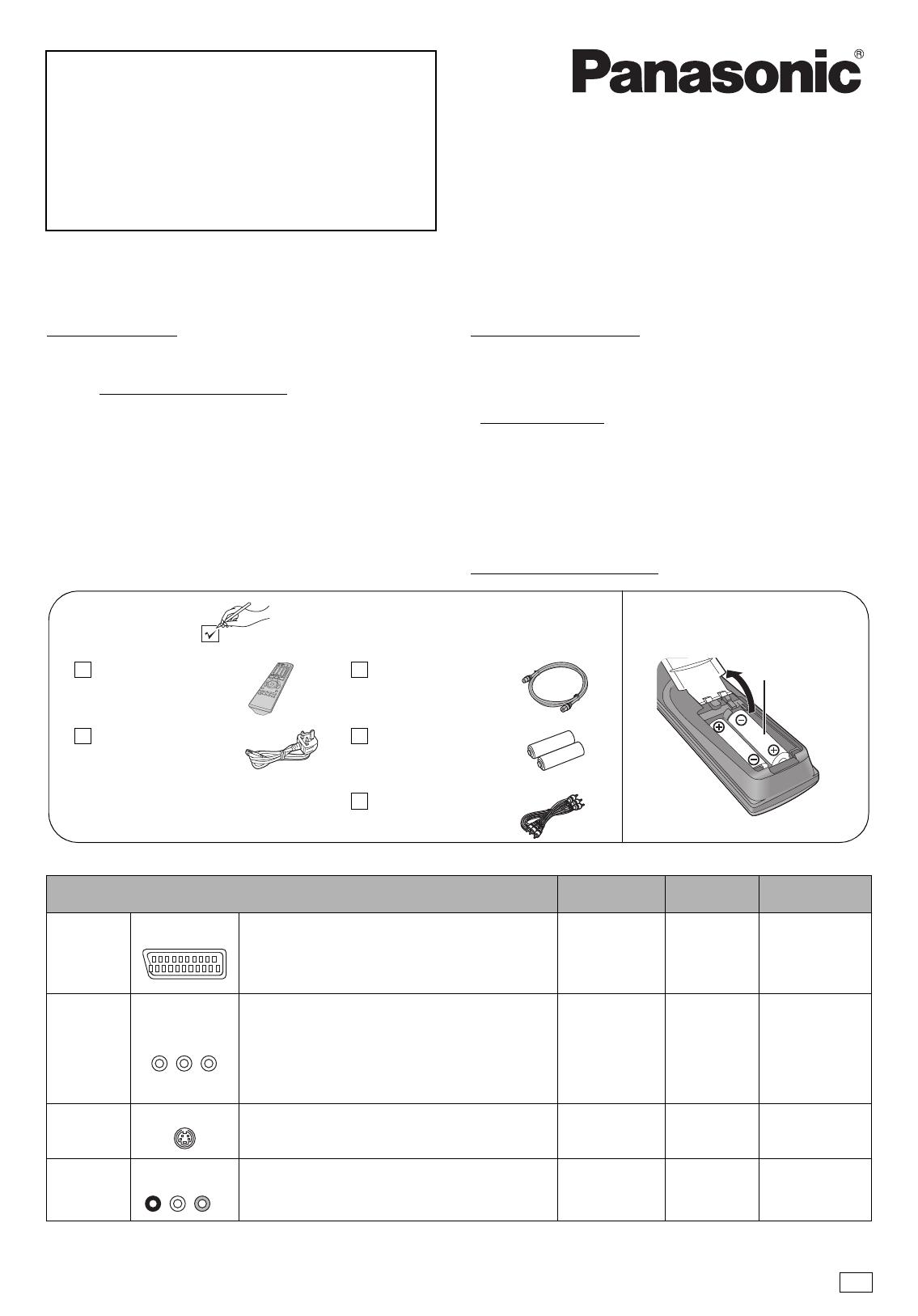
Included
accessories
1 RF coaxial lead
(VJA1089)
1 AC mains lead
(RJA0044-3C)
≥For use with this unit only. Do not
use it with other equipment.
Also, do not use cords for other
equipment with this unit.
1 Audio/video cable
(VJA0788-D)
1 Remote control
(EUR7729KE0)
2 Batteries
for remote control
Insert the batteries into the
remote control
R6/LR6, AA
Please check and identify the supplied accessories.
Use numbers when asking for replacement parts.
(Product numbers correct as of February 2005. These may
be subject to change.)
AV IN
COMPONENT
VIDEO IN
S-VIDEO IN
AUDIO IN
R L
VIDEO IN
RQCA1352-1
EB
Page1-3and6.fm Page 1 Tuesday, March 8, 2005 9:06 AM


