
OPERATOR'S MANUAL
13 in. (330 mm) Portable Planer
Model AP1300
THANK YOU FOR BUYING A RYOBI PORTABLE PLANER.
Your new planer has been engineered and manufactured to Ryobi's high standards for dependability, ease of operation,
and operator safety. Properly cared for, it will give you years of rugged, trouble-free performance.
CAUTION: Carefully read through this entire operator's manual before using your new planer.
Pay close attention to the Rules for Safe Operation, Warnings, and Cautions. If you use your tool properly and only for
what it is intended, you will enjoy years of safe, reliable service.
Please fill out and return the Warranty Registration Card so we can be of future service to you.
Thank you again for buying Ryobi tools.
SAVE THIS MANUAL FOR FUTURE REFERENCE

Page 2
TABLE OF CONTENTS
■ Table of Contents, Introduction, and Product Specifications ...........................................................................................2
■ Rules For Safe Operation............................................................................................................................................. 3-5
■ Electrical............................................................................................................................................................................6
■ Unpacking and Loose Parts..............................................................................................................................................7
■ Features............................................................................................................................................................................8
■ Assembly...........................................................................................................................................................................9
■ Adjustments..............................................................................................................................................................10-12
■ Operation.................................................................................................................................................................. 13-14
■ Maintenance ............................................................................................................................................................. 15-16
■ Troubleshooting ............................................................................................................................................................. 17
■ Parts Ordering/Service.................................................................................................................................................. 18
PRODUCT SPECIFICATIONS
SPECIFICATIONS:
Feed Rate 25 FPM
Rating 15 Amperes
No Load Speed 9,900 RPM
Input 120 volts, 60Hz, AC Only
Max. Planing Height 6 in. (152 mm)
Max. Planing Width 13 in. (330 mm)
Max Planing Depth 1/8 in. (3 mm)
Net Weight 77 lbs. (35 kg.)
INTRODUCTION
Your portable planer has many features for making cutting
operations more pleasant and enjoyable. Safety,
performance, and dependability have been given top priority
in the design of this planer making it easy to maintain and
operate.
CAUTION:
Carefully read through this entire operator's manual
before using your new tool. Pay close attention to the
Rules for Safe Operation, and all Safety Alert Symbols
including Danger, Warning and Caution. If you use your
tool properly and only for what it is intended, you will
enjoy years of safe, reliable service.
Look for this symbol to point out important safety precautions.
It means attention!!! Your safety is involved.

Page 3
Safe operation of this power tool requires that you read and
understand this operator's manual and all labels affixed to
the tool. Safety is a combination of common sense, staying
alert, and knowing how your tool works.
READ ALL INSTRUCTIONS
■ KNOW YOUR POWER TOOL. Read the operator's
manual carefully. Learn the machine's applications and
limitations as well as the specific potential hazards re-
lated to this tool.
■ GUARD AGAINST ELECTRICAL SHOCK by prevent-
ing body contact with grounded surfaces such as pipes,
radiators, ranges, refrigerator enclosures.
■ KEEP GUARDS IN PLACE and in good working order.
■ REMOVE WRENCHES AND ADJUSTING KEYS. Get in
the habit - before turning on tool - that hex keys and
adjusting wrenches are removed from tool.
■ KEEP THE WORK AREA CLEAN. Cluttered work areas
and work benches invite accidents. DO NOT leave tools
or pieces of wood on the machine while it is in operation.
■ DO NOT USE IN DANGEROUS ENVIRONMENTS. Do
not use power tools near gasoline or other flammable
liquids, in damp or wet locations, or expose them to rain.
Keep the work area well lit.
■ KEEP CHILDREN AND VISITORS AWAY. All visitors
should wear safety glasses and be kept a safe distance
from work area. Do not let visitors contact tool or exten-
sion cord while operating.
■ MAKE WORKSHOP CHILDPROOF with padlocks and
master switches or by removing starter keys.
■ DO NOT FORCE THE TOOL. It will do the job better and
safer at the rate for which it was designed.
■ USE THE RIGHT TOOL FOR THE JOB. Do not force the
tool or attachment to do a job it was not designed for. Use
it only the way it was intended.
■ USE THE PROPER EXTENSION CORD. Make sure
your extension cord is in good condition. Use only a cord
heavy enough to carry the current your product will draw.
An undersized cord will cause a drop in line voltage
resulting in loss of power and overheating. A wire gage
size (A.W.G.) of at least 14 is recommended for an
extension cord 25 feet or less in length. If in doubt, use the
next heavier gage. The smaller the gage number, the
heavier the cord.
■ INSPECT TOOL CORDS AND EXTENSION CORDS
PERIODICALLY and, if damaged, have repaired at your
nearest authorized service center. Stay constantly aware
of cord location and keep it well away from the moving
blade.
■ DRESS PROPERLY. Do not wear loose clothing, gloves,
neckties, rings, bracelets, or other jewelry that can get
caught and draw you into moving parts. Nonslip footwear
is recommended. Also wear protective hair covering to
contain long hair.
■ ALWAYS WEAR SAFETY GLASSES WITH SIDE
SHIELDS. Everyday eyeglasses have only impact-resis-
tant lenses; they are NOT safety glasses.
RULES FOR SAFE OPERATION
■ WEAR A DUST MASK to keep from inhaling fine par-
ticles.
■ PROTECT YOUR HEARING. Wear hearing protection
during extended periods of operation.
■ SECURE WORK. Use clamps or a vise to hold work
when practical. It's safer than using your hand and frees
both hands to operate tool.
■ DO NOT OVERREACH. Keep proper footing and bal-
ance at all times.
■ MAINTAIN TOOLS WITH CARE. Keep tools sharp and
clean for better and safer performance. Follow instruc-
tions for lubricating and changing accessories.
■ DISCONNECT ALL TOOLS. When not in use, before
servicing, or when changing attachments, all tools should
be disconnected.
■ AVOID ACCIDENTAL STARTING. Be sure switch is off
when plugging in any tool.
■ USE RECOMMENDED ACCESSORIES. Consult the
operator's manual for recommended accessories. The
use of improper accessories may cause risk of injury.
■ NEVER STAND ON TOOL. Serious injury could occur if
the tool is tipped or if the blade is unintentionally contacted.
■ CHECK DAMAGED PARTS. Before using the tool, a
guard or other part that is damaged should be carefully
checked to determine that it will operate properly and
perform its intended function. Check for alignment of
moving parts, binding of moving parts, breakage of parts,
mounting and any other conditions that may affect its
operation. A guard or other part that is damaged must be
properly repaired or replaced by an authorized service
center to avoid risk of personal injury.
■ DIRECTION OF FEED. Feed work into a blade or cutter
against the direction or rotation of the blade or cutter only.
■ NEVER LEAVE TOOL RUNNING UNATTENDED, TURN
THE POWER OFF. Do not leave tool until it comes to a
complete stop.
■ FIRMLY CLAMP OR BOLT your tool to a workbench or
table at approximately hip height.
■ KEEP HANDS AWAY FROM CUTTING AREA. Do not
reach underneath work or in blade cutting path with your
hands and fingers for any reason. Always turn the power
off.
■ DO NOT ABUSE CORD. Never yank cord to disconnect
it from receptacle. Keep cord from heat, oil, and sharp
edges.
■ USE ONLY OUTDOOR EXTENSION CORDS. Use only
extension cords with the marking "Acceptable for use
with outdoor appliances; store cords indoors while not in
use". Use extension cords with an electrical rating not
less than the planer's electrical rating. Always disconnect
the extension cord from the outlet before disconnecting
the product from the extension cord.
■ DO NOT USE TOOL IF SWITCH DOES NOT TURN IT
ON AND OFF. Have defective switches replaced by an
authorized service center.

Page 4
■ DO NOT attempt to turn cutter-head with hands.
■ WHEN SERVICING, use only identical Ryobi replace-
ment parts. Use of any other parts may create a hazard
or cause product damage.
■ NEVER USE THIS TOOL IN AN EXPLOSIVE ATMO-
SPHERE. Normal sparking of the motor could ignite
fumes.
■ IF ANY PART OF THIS TOOL IS MISSING or should
break, bend, or fail in any way, or should any electrical
component fail to perform properly, shut off the power
switch, remove the plug from the power source and have
damaged, missing, or failed parts replaced before resum-
ing operation.
■ DO NOT OPERATE THIS TOOL WHILE UNDER THE
INFLUENCE OF DRUGS, ALCOHOL, OR ANY MEDI-
CATION.
■ ALWAYS STAY ALERT! Do not allow familiarity (gained
from frequent use of your planer) to cause a careless
mistake. ALWAYS REMEMBER that a careless fraction
of a second is sufficient to inflict serious injury.
■ STAY ALERT AND EXERCISE CONTROL. Watch what
you are doing and use common sense. Do not operate
tool when you are tired. Do not rush.
■ MAKE SURE THE WORK AREA HAS AMPLE LIGHT-
ING to see the work and that no obstructions will interfere
with safe operation BEFORE performing any work using
your planer.
■ ALWAYS TURN OFF THE TOOL before disconnecting
it to avoid accidental starting when reconnecting to power
supply. NEVER leave the tool unattended while con-
nected to a power source.
■ SAVE THESE INSTRUCTIONS. Refer to them frequently
and use them to instruct other users. If you loan someone
this tool, loan them these instructions also.
WARNING:
Some dust created by power sanding, sawing, grinding,
drilling, and other construction activities contains chemi-
cals known to cause cancer, birth defects or other repro-
ductive harm. Some examples of these chemicals are:
• lead from lead-based paints,
• crystalline silica from bricks and cement and
other masonry products, and
• arsenic and chromium from chemically-treated
lumber.
Your risk from these exposures varies, depending on how
often you do this type of work. To reduce your exposure
to these chemicals, work in a well ventilated area and
work with approved safety equipment, such as those dust
masks that are specially designed to filter out microscopic
particles.
RULES FOR SAFE OPERATION
■ KEEP TOOL DRY, CLEAN, AND FREE FROM OIL AND
GREASE. Always use a clean cloth when cleaning. Never
use brake fluids, gasoline, petroleum-based products, or
any solvents to clean tool.
■ NEVER PERFORM THE PLANING OPERATION with
the cutter head or drive guard removed.
■ NEVER MAKE A PLANING CUT deeper that 1/8 in.
(3 mm)
■ DO NOT PLANE MATERIAL shorter than 14 in. (356mm)
or narrower than 3/4 in. (19 mm).
■ MAINTAIN THE PROPER RELATIONSHIP between the
infeed and outfeed surfaces and the cutter head knife
path.
■ SUPPORT THE WORKPIECE ADEQUATELY at all
times during operation; maintain control of the work at
all times.
■ DO NOT BACK THE WORK toward the infeed table.
■ DO NOT ATTEMPT TO PERFORM an abnormal or little
used operation without the use of sturdy and adequate
jigs, fixtures, stops, and the like.
■ NEVER cut more than one piece at a time. DO NOT
STACK more than one workpiece on the planer table at
a time.
■ BEFORE STARTING UP, recheck to make certain all
holding screws are tight.
■ STOP THE MACHINE and recheck the cutter head gib
screws and knives for tightness after about 50 hours of
operation.
■ DO NOT FORCE FEED THE WORKPIECE through the
machine. Let the planer apply the proper feed rate
■ CHECK THE FEED ROLLERS occasionally to be sure
there are no chips or sawdust between any components.
If the rollers are not seated firmly, they will not hold the
stock firmly against the bed and are likely to cause
kickback.
■ PLANE ONLY SOUND LUMBER; there should be no
loose knots and as few tight knots as possible. Make sure
the workpiece is free from nails, screws, stones, or other
foreign objects that could break or chip the knives.
■ NEVER STAND DIRECTLY IN LINE with either the
infeed or outfeed sides. Stand off to one side.
■ MAKE SURE THE KNIVES ARE ATTACHED as de-
scribed in the operation section. The knives are sharp and
can easily cut your hand. Use caution in handling the
knives and cutter head guard.
■ NEVER PUT YOUR FINGERS into the dust chute or
under the knife guard.
■ ALLOW THE CUTTER HEAD to reach full speed before
using the planer.
■ REPLACEMENT PARTS. All repairs, whether electrical
or mechanical, should be made at your nearest autho-
rized service center.
SAVE THESE INSTRUCTIONS

Page 5
RULES FOR SAFE OPERATION
The purpose of safety symbols is to attract your attention to possible dangers. The safety symbols, and the explanations
with them, deserve your careful attention and understanding. The safety warnings do not by themselves eliminate any
danger. The instructions or warnings they give are not substitutes for proper accident prevention measures.
SYMBOL MEANING
SAFETY ALERT SYMBOL:
Indicates danger, warning or caution. May be used in conjunction with other symbols or pictographs.
DANGER: Failure to obey a safety warning will result in serious injury to yourself or to others. Always
follow the safety precautions to reduce the risk of fire, electric shock and personal injury.
WARNING: Failure to obey a safety warning can result in serious injury to yourself or to others. Always
follow the safety precautions to reduce the risk of fire, electric shock and personal injury.
CAUTION: Failure to obey a safety warning may result in property damage or personal injury to yourself
or to others. Always follow the safety precautions to reduce the risk of fire, electric shock and personal
injury.
Note: Advises you of information or instructions vital to the operation or maintenance of the equipment.
WARNING:
The operation of any power tool can result in foreign objects being thrown into your eyes, which can
result in severe eye damage. Before beginning tool operation, always wear safety goggles or safety
glasses with side shields and a full face shield when needed. We recommend Wide Vision Safety
Mask for use over eyeglasses or standard safety glasses with side shields. Always wear eye
protection which is marked to comply with ANSI Z87.1.
WARNING:
Do not attempt to operate this tool until you have read
thoroughly and understand completely all instructions,
safety rules, etc., contained in this manual. Failure to
comply can result in accidents involving fire, electric
shock, or serious personal injury. Save operator's manual
and review frequently for continuing safe operation, and
instructing others who may use this tool.
IMPORTANT
Servicing requires extreme care and knowledge and should
be performed only by a qualified service technician. For
service we suggest you return the tool to your nearest
RYOBI AUTHORIZED SERVICE CENTER for repair. When
servicing, use only identical Ryobi replacement parts.
SAFETY AND INTERNATIONAL SYMBOLS
This operator’s manual describes safety and international symbols and pictographs that may appear on this product.
Read the operator’s manual for complete safety, assembly, operating and maintenance, and repair information.
MEANING
Do not expose to rain or use in damp locations

Page 6
ELECTRICAL
EXTENSION CORDS
Use only 3-wire extension cords that have 3-prong ground-
ing plugs and 3-pole receptacles that accept the tool's plug.
When using a power tool at a considerable distance from the
power source, use an extension cord heavy enough to carry
the current that the tool will draw. An undersized extension
cord will cause a drop in line voltage, resulting in a loss of
power and causing the motor to overheat. Use the chart
provided below to determine the minimum wire size required
in an extension cord. Only round jacketed cords listed by
Underwriter's Laboratories (UL) should be used.
Length of Extension Cord Wire Size (A.W.G.)
Up to 25 feet 14
26-50 feet 12
When working with the tool outdoors, use an extension cord
that is designed for outside use. This is indicated by the
letters WA on the cord's jacket.
Before using an extension cord, inspect it for loose or
exposed wires and cut or worn insulation. Repair or replace
a damaged or worn cord immediately.
CAUTION:
Keep the cord away from the cutting area and position
the cord so that it will not be caught on material, tools, or
other objects during cutting.
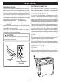
GROUNDING
PIN
COVER OF GROUNDED
OUTLET BOX
ELECTRICAL CONNECTION
Your Ryobi Portable Planer is powered by a precision built
electric motor. It should be connected to a power supply
that is 120 volts, 60 Hz. If the machine does not operate
when plugged into an outlet, double check the power supply.
GROUNDING INSTRUCTIONS
In the event of a malfunction or breakdown, grounding
provides a path of least resistance for electric current to
reduce the risk of electric shock. This tool is equipped with an
electric cord having an equipment-grounding conductor and
a grounding plug. The plug must be plugged into a matching
outlet that is properly installed and grounded in accordance
with all local codes and ordinances.
Do not modify the plug provided. If it will not fit the outlet, have
the proper outlet installed by a qualified electrician. Improper
connection of the equipment-grounding conductor can result
in a risk of electric shock. The conductor with insulation
having an outer surface that is green with or without yellow
stripes is the equipment-grounding conductor. If repair or
replacement of the electric cord or plug is necessary, do not
connect the equipment-grounding conductor to a live
terminal.
Check with a qualified electrician or service personnel if the
grounding instructions are not completely understood, or if in
doubt as to whether the tool is properly grounded.
Repair or replace a damaged or worn cord immediately.
This tool is intended for use on a circuit that has an outlet like
the one shown in
Figure 1.
It also has a grounding pin like the
one shown.
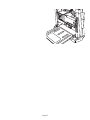
CORD STORAGE BAG
See Figure 1.
For convenience and safety, your planer comes equipped
with a cord storage bag. This storage bag is on the under-
neath side of the rear table extension and allows you to fold
the cord and place it in the bag for storage or transport.

Page 7
UNPACKING
■ Carefully lift the tool from the carton and place it on a
level work surface. This machine is heavy. Avoid back
injury and get help when needed.
■ Do not discard the packing materials until you have
carefully inspected the tool, identified all loose parts, and
satisfactorily operated your new planer.
■ Examine all parts to make sure no breakage or damage
has occurred during shipping.
If any parts are damaged or missing, do not attempt to plug
in the power cord and turn the switch on until the damaged
or missing parts are obtained and are installed correctly.
WARNING:
To prevent accidental starting that could cause possible
serious personal injury, assemble all parts, make sure all
adjustments are complete, and make sure all fasteners
are secure before connecting portable planer to power
supply. Portable planer should never be connected to
power supply when you are assembling parts, making
adjustments, installing or removing blades, or when not in
use.
Your portable planer has been shipped completely
assembled except for the dust chute and dust chute knobs.
■ Remove all loose parts from the carton.
■ Separate and check with the list of loose parts.
See
Figure 2.
■ Remove the packing materials from around your planer.
WARNING:
If any parts are missing, do not operate this tool until the
missing parts are replaced. Failure to do so could result
in possible serious personal injury.

Page 8

Page 9
ASSEMBLY
INSTALLING THE DUST CHUTE
See Figure 4.
■ Unplug your planer.
WARNING:
Failure to turn the planer off, remove the switch key, and
unplug the planer before servicing or making adjustments
could result in accidental starting causing possible
serious personal injury.
■ From the back of the machine, locate the two screws on
the cutter head assembly.
See Figure 4.
Turning coun-
terclockwise, loosen each screw.
■ Slide the dust chute between the lock washer and the
cutter head assembly, resting the dust chute on the
rubber bumper.
■ Insert the two dust chute knobs, turning clockwise.
■ Securely tighten the screws and dust chute knobs.
Note: To minimize sawdust accumulation on your
workpiece, attach either a 2-1/2 in. (64 mm) or 4 in.
(102 mm) shop vac hose to the end of the dust chute.
MOUNTING PLANER TO WORKBENCH
If your planer is to be used in a permanent location, it is
recommended you secure it to a workbench or other stable
surface. When mounting the planer to a workbench, holes
should be drilled through the supporting surface of the
workbench.
■ Mark holes on workbench where planer is to be mounted
using holes in planer base as a template for hole
pattern.
■ Drill four holes through workbench.
■ Place planer on workbench aligning holes in the planer
base with holes drilled in the workbench.
■ Insert four bolts (not included) and tighten securely with
lock washers and hex nuts (not included).
Note: All bolts should be inserted from the top. Install
the lock washers and hex nuts from the underside of the
workbench.
Supporting surface where planer is mounted should be
examined carefully after mounting to insure that no move-
ment during use can result. If any tipping or walking is
noted, secure workbench or support surface before begin-
ning planing operation.
CLAMPING PLANER TO WORKBENCH
See Figure 5.
If the planer is to be used as a portable tool, it is recom-
mended you fasten it permanently to a mounting board that
can easily be clamped to a workbench or other stable
surface. The mounting board should be of sufficient size to
avoid tipping while planer is in use. Any good grade ply-
wood or chipboard with a 3/4 in. (19 mm) thickness is
recommended.
Fig. 5
Fig. 4
■ Mark holes on board where planer is to be mounted
using holes in planer base as a template for hole
pattern.
■ Follow last three steps in section
Mounting Planer to
Workbench.
If lag bolts are used, make sure they are long enough to go
through holes in planer base and material the planer is
being mounted to. If machine bolts are used, make sure
bolts are long enough to go through holes in planer base,
the material being mounted to, and the lock washers and
hex nuts.
SCREWS
DUST
CHUTE
DUST CHUTE
KNOBS

Page 10
ADJUSTMENTS
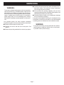
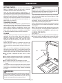
LEVELING THE TABLE EXTENSIONS
See Figure 6.
The infeed and outfeed table extensions are attached to
the planer. Shipped in a folded, "upright" position, the
table extensions must be in the "down" position before
planing can begin. For accurate planing, table exten-
sions must be level with the planer table.
Note: For optimum performance, always check to make
sure the table extensions are level before beginning
planing operations.
To Level:
■ Unplug your planer.
WARNING:
Failure to unplug your planer could result in accidental
starting causing possible serious personal injury.
■ Place a straight edge or level across both the planer
table and table extensions.
■ If adjustment is necessary, lift table extensions and
loosen lock nuts. Adjust stop screws (one on each side)
until extension table is level with planer table.
■ Press down on the table extension to ensure the table
extension is properly seated.
■ Tighten lock nuts securely when adjustments are com-
plete.
Note: Four screws attach table extensions to support
bars; loosening these screws may aid in leveling
table extensions.
BLADE HEIGHT ADJUSTMENT
See Figure 7.
Raising and lowering the depth adjustment handle controls
the depth of cut on your planer.
Note: Never adjust blade height with cutter lock in the
"locked" position (pushed to the far right).
To Raise:
■ Push cutter lock to the left to unlock cutter head
assembly.
■ Turn the depth adjustment handle clockwise to desired
height.
■ Once cutter head is in desired position, lock cutter head
assembly in place by pushing cutter lock handle to the
right.
To Lower:
■ Push cutter lock to the left to unlock cutter head
assembly.
■ Turn the depth adjustment handle counterclockwise to
desired height.
■ Once cutter head assembly is in the desired position,
lock cutter head in place by pushing cutter lock handle
to the right.
Note: Each complete rotation of the handle moves the
cutter head assembly 5/64 in. (2 mm).
Fig. 6
Fig. 7
LOCK NUT
STOP SCREWS
TABLE
EXTENSION
PLANER
TABLE
LOCK
CUTTER HEAD
ASSEMBLY
DEPTH
ADJUSTMENT
HANDLE
UNLOCK
1-3/4
1-1/2
1-1/4
1/4
0

Page 11

Page 12
ADJUSTMENTS
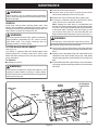
CUTTER BLADE SIDEWAYS ADJUSTMENT
See Figures 10 and 11.
During the use of your planer, tiny nicks may appear on
the cutter blades. This is a result of picking up sand or
other particles on the workpiece and then running the
workpiece through the planer. To eliminate any imper-
fections during the planing process, adjust one or both
cutter blades laterally.
To Adjust:
■ Unplug your planer.
WARNING:
Failure to turn the planer off, remove the switch key, and
unplug the planer could result in accidental starting
causing possible serious personal injury.
■ Lower the cutter head assembly.
■ From the back of the planer, remove the two screws
holding the dust chute in place.
■ Remove the dust chute then lift off the safety cover.
■ Rotate the cutter block until it locks in place (every 180°
turn).
Note: From beneath the cutter head assembly, using the
planer table as a mirror, touch the threaded spindle where
it meets the planer table. Carefully move your fingers up
toward the drive belt until you touch it. Turn the drive belt
with your fingers until the cutter head locks in place
(see
Figure 11.)
WARNING:
To avoid injury, NEVER rotate the cutter block by hand.
■ Loosen the socket head bolts holding the blade binder
and cutter blade to the cutter block.
■ Move the cutter blade to the left or right side up to 3/64 in.
(1 mm) laterally using a flat head screwdriver.
■ Retighten the socket head bolts securely.
■ Place the safety cover on the cutter head assembly
leaving the screws loose.
■ Reinstall the dust chute by slipping it under the screws
and lock washers (see page 9).
■ Tighten screws securely.
Note: Cutter blades require only slight adjustments to
offset planing imperfections.
Fig. 10
Fig. 11
SAFETY
COVER
CUTTER
BLOCK
SCREWS
CUTTER
BLOCK
BLADE
BINDER

Page 13
ON
OPERATION
GETTING STARTED
Before turning on the planer, check for loose fasteners,
fittings, or hardware. Be sure the dust cover is securely
mounted and that the blade cutter rotates freely.
Lower the cutter head assembly to approximately 1 in.
(25mm) above the planer table surface. Without putting any
load on the planer, test the motor by turning the planer on and
allowing it to reach full speed. If the planer sounds exces-
sively loud or has excessive vibration, turn off the machine
immediately and check again for any loose hardware, re-
tightening any you may find.
THICKNESS PLANING
Thickness planing sizes workpiece to desired thickness
while creating a smooth, level surface. Thickness of each
cut will depend on type of wood (hardwood versus soft-
wood), width of workpiece, straightness, dryness, and
grain composition. Whenever working with a new type of
wood, make thin test cuts on a scrap piece of wood first
to determine potential problems with the workpiece.
PLANING
Thickness planers work best if at least one side of the
workpiece has a flat surface. When both sides of a
workpiece is rough, use a surface planer or jointer first to
define the initial flat surface. Plane one side of the
workpiece then flip the workpiece and plane the surface
of the reverse side.
Always plane both sides of a workpiece to reach the
desired thickness. This will leave the workpiece with
uniform moisture to prevent warp during the drying pro-
cess.
When one end of the workpiece is thicker than the oppo-
site end by more than 1/8 in. (3 mm), make several cuts
with the planer starting with light planing cuts first. Re-
member, light cuts create a finer finish than heavier cuts.
■ Do not plane a workpiece less than 3/16 in. (5 mm)
thick.
■ Do not plane a workpiece less than 3/4 in. (19 mm) wide.
■ Do not plane workpiece shorter than 14 in. (356 mm) long
as this will cause kickback.
■ Do not plane more than one workpiece at a time.
■ Do not lower the cutter head assembly lower than 3/16 in.
(5 mm)
Do not continuously use the planer set at the maximum depth
of cut (1/8 in., 3 mm) and at full width of cut (13 in., 330mm).
Continuous use at maximum cutting capacity will damage
the motor.
WARNING:
Never plane workpiece with loose knots or foreignobjects.
Do not plane workpieces that are severely bowed,
twisted, or knotted. Cutter blades can dull, chip, or
break causing possible serious personal injury.
Fig. 12
SWITCH KEY
OFF
. WARNING:
Always wear safety goggles or safety glasses with side
shields during power tool operation or when blowing dust.
If operation is dusty, also wear a dust mask.
Worn cutter blades will affect cutting accuracy. Planing with
dull or nicked cutter blades may produce ridges or rough
workpiece surfaces.
Gum and pitch on the cutter blades will cause them to wear
prematurely. Using a gum and pitch remover to keep your
cutter blades clean will prolong their wear.
Refer to the
Maintenance Section
of this operator's manual
for instructions on how to remove and replace or turn the
cutter blades.
Note: Cutter blades are double-edged and can be turned
once to the opposite, unused edge before replacement is
required. Cutter blades must ALWAYS be replaced as a set.
LOCKING THE SWITCH
See Figure 12.
■ Wait until the planer has come to a full and complete stop.
■ Place the switch in the OFF position, remove the switch
key from the switch assembly. Store key in safe place.

Page 14

Page 15
WARNING:
When servicing, use only identical Ryobi replacement
parts. Use of any other part may create a hazard or cause
product damage.
GENERAL
Avoid using solvents when cleaning plastic parts. Most
plastics are susceptible to damage from various types of
commercial solvents and may be damaged by their use. Use
clean cloths to remove dirt, carbon dust, etc.
WARNING:
Do not at any time let brake fluids, gasoline, petroleum-
based products, penetrating oils, etc. come in contact
with plastic parts. They contain chemicals that can
damage, weaken or destroy plastic.
CUTTER BLADE REPLACEMENT
See Figure 15.
Your planer is equipped with two double-edged cutter
blades attached to a rotating cutter block. Worn cutter
blades will affect cutting accuracy and may produce ridges
on the workpiece.
To Replace:
■ Unplug your planer.
WARNING:
Failure to turn the planer off, remove the switch key, and
unplug the planer before servicing or making adjust-
ments could result in accidental starting causing possible
serious personal injury.
MAINTENANCE
■ Lower the cutter head assembly.
■ From the back of the planer, remove the two socket
head screws holding the dust chute in place.
■ Remove the dust chute then lift off the safety cover.
■ If necessary, rotate the cutter block until it locks in place
(every 180° turn the cutter block will lock).
Note: Rotating the cutter block is accomplished from
beneath the cutter head assembly. Using the planer table
as a mirror, touch the threaded spindle where it attaches
to the planer table. Carefully move your fingers up until
you touch the drive belt. Turn the drive belt with your
fingers until the cutter head locks in place (
see Figure 11
).
WARNING:
To avoid injury, never rotate the cutter block by hand.
■ Carefully remove the socket head bolts.
■ Place your thumb and index finger on the finger tabs and
carefully lift the blade binder and cutter blade off the cutter
block.
■ Lightly oil new cutter blade. Align the cutter blade on the
underside of the blade binder placing the cutter blade
(sloped edge against the blade binder) in the small oval
tabs.
■ Place blade binder with cutter blades on the cutter block
in the large oval tabs and aligning with the six socket head
bolt holes.
Fig. 15
CUTTER BLOCK
LOCK BUTTON
FINGER TABS
SOCKET HEAD
BOLT
BLADE
BINDER
CUTTER
BLADE
LARGE OVAL
TAB
SMALL OVAL
TABS

Page 16
MAINTENANCE
■ Securely retighten the hex head bolts.
■ Depress the cutter block lock button and rotate the cutter
block 180°.
■ Repeat the above steps for the second blade.
■ Place the safety cover on the cutter head assembly
leaving the socket head screws loose.
■ Reinstall the dust chute by slipping it under the socket
head screws and lock washers (see page 9).
■ Tighten socket head screws securely.
Note: Cutter blades require only slight adjustments to
offset planing imperfections.
LUBRICATION
Periodically, check all moving parts (spindle, roller surfaces,
handles, etc.) to ensure they are clean and well lubricated.
A light film of oil wiped on the face of the cutter blades will
keep them rust-free. All of the bearings in this tool are
lubricated with a sufficient amount of high grade lubricant for
the life of the unit under normal operating conditions. No
further lubrication is required.
MOTOR/ELECTRICAL
The universal motor is easy to maintain but must be kept
clean. Do not allow water, oil or sawdust to accumulate on or
in it. The sealed bearings are permanently lubricated and
need no further attention.
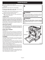
BRUSH REPLACEMENT
See Figure 16.
Your planer has externally accessible brush assemblies that
should be checked every 10 to 15 operating hours for wear.
To inspect or replace these brushes, unscrew the brush cap
located at the right front and left rear of the planer. Be sure
to replace the brush cap securely after inspection or repairs.
CLEANING
Sawdust buildup and other debris can cause the tool to plane
inaccurately. Periodic cleaning and waxing is needed for
accurate, precision planing.
Do not allow sawdust to accumulate on the planer. Clean the
dust chute after each use. Moving parts should be cleaned
regularly with penetrating oil and lubricated with a light
coating of medium-weight machine oil.
Paste wax should be applied to the planing table surface to
ease the movement of workpieces across it. Paste wax can
also be used on infeed and outfeed support surfaces but be
careful not to use so much that it will be absorbed into the
wood and interfere with staining.
Check feed rollers after each use for resin buildup because
they must be clean to be effective. If buildup occurs, use a
mild, nonflammable tar and pitch remover.
Fig. 16
WARNING:
Always wear safety goggles or safety glasses with side
shields during power tool operation or when blowing dust.
If operation is dusty, also wear a dust mask.
WARNING:
To ensure safety and reliability, all repairs should be
performed by a qualified service technician at a Ryobi
Authorized Service Center to avoid risk of personal
injury.
BRUSH CAP
BRUSH

Page 17
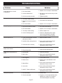
1. Replace, turn or sharpen cutter blades
2. Butt pieces end-to-end as they are fed
into planer
3. Tighten lag bolts
1. Reduce depth of cut
2. Feed other end of board first
3. Replace, turn or sharpen cutter blades
1. Dry wood before planing
2. Replace, turn or sharpen cutter blades
3. Reduce depth of cut
4. Check for adequate power supply,
check cord and plug for damage,
check condition of motor brushes
1. Adjust elevation screws
2. Have service performed by Ryobi
Authorized Service Center
3. Have service performed by Ryobi
Authorized Service Center
1. Adjust depth scale
2. Clean and wax planing table
1. Clean and lubricate
2. Have service performed by Ryobi
Authorized Service Center
1. Check power source
2. Replace fuse, reset breaker or call
Electrician
3. Have service performed by Ryobi
Authorized Service Center
4. Have service performed by Ryobi
Authorized Service Center
5. Have service performed by Ryobi
Authorized Service Center
1. Reduce load
2. Operate on circuit separate from other
appliances or motors or connect to
circuit with adequate amp rating
1. Dull cutter blades
2. Incorrect butted stock
3. Unit not securely mounted
1. Too deep a blade setting
2. Workpiece being fed against
grain
3. Dull cutter blades
1. High wood moisture content
2. Dull cutter blades
3. Too deep a blade setting
4. Incorrect feeding speed
1. Cutter head assembly not level
with planer surface
2. Unstable roller spring pressure
3. Feed roller worn unevenly
1. Depth scale incorrectly set
2. Dirty planing table
1. Dirty spindle
2. Worn chain
1. Not plugged in
2. Blown circuit
3. Motor failure
4. Loose wire
5. ON/OFF Switch malfunction
1. Unit overloaded
2. Circuit overloaded
Problem Cause Solution
Snipe (depressions at ends
of workpiece)
Torn grain
Fuzzy/Rough grain
Uneven depth of cut
Board thickness does not match
depth scale indicator
Cutter head height difficult to
adjust
Will not start
Interrupted operation
TROUBLESHOOTING

Page 18
983000-045
5-02
RYOBI TECHNOLOGIES, INC.
1428 Pearman Dairy Road Anderson SC 29625
Post Office Box 1207 Anderson SC 29622-1207
Phone 1-800-525-2579
www.ryobitools.com
OPERATOR'S MANUAL
13 in. (330 mm) Portable Planer
Model AP1300
• SERVICE
Now that you have purchased your tool, should a need ever exist for repair parts or
service, simply contact your nearest Ryobi Authorized Service Center. Be sure to
provide all pertinent facts when you call or visit. Please call 1-800-525-2579 for your
nearest Ryobi Authorized Service Center. You can also check our web site at
www.ryobitools.com for a complete list of Authorized Service Centers.
• MODEL NO.
The model and serial numbers of your tool will be found on a plate attached to the motor
housing. Please record the serial number in the space provided below.
• MODEL NUMBER AP1300
• SERIAL NUMBER
EXTENSION CORD CAUTION
When using a power tool at a considerable distance from a
power source, be sure to use an extension cord that has the
capacity to handle the current the tool will draw. An undersized
cord will cause a drop in line voltage, resulting in overheating
and loss of power. Use the chart to determine the minimum
wire size required in an extension cord. Only round jacketed
cords should be used.
When working with a tool outdoors, use an extension cord that
is designed for outside use. This is indicated by the letters
"WA" on the cord's jacket.
Before using any extension cord, inspect it for loose or ex-
posed wires and cut or worn insulation.
**Ampere rating
(on tool data plate) 0-2.0 2.1-3.4 3.5-5.0 5.1-7.0 7.1-12.0 12.1-16.0
Cord Length Wire Size (A.W.G.)
25' 16 16 16 16 14 14
50' 16 16 16 14 14 12
CAUTION: Keep the extension cord clear of the working
area. Position the cord so that it will not get caught on
workpiece, tools, or other obstructions while you are working
with a power tool.
**Used on 12 gauge - 20 amp circuit.
-
 1
1
-
 2
2
-
 3
3
-
 4
4
-
 5
5
-
 6
6
-
 7
7
-
 8
8
-
 9
9
-
 10
10
-
 11
11
-
 12
12
-
 13
13
-
 14
14
-
 15
15
-
 16
16
-
 17
17
-
 18
18


Ryobi Planer AP1300 User manual
- Type
- User manual
- This manual is also suitable for
Ask a question and I''ll find the answer in the document
Finding information in a document is now easier with AI
Related papers
-
Ryobi AP1305 Owner's manual
-
Ryobi Planer AP1301 User manual
-
-
-
-
-
-
-
-
Other documents
-
RIDGID TP1300LS User manual
-
MasterCraft 55-5503-4 Operating And Safety Instructions Manual
-
-
Rikon Power Tools 25-130H Owner's manual
-
General International 30-005HC M1 User guide
-
-
-
King Canada KC-13HPC User manual
-
-