Page is loading ...

INSTALLATION INSTRUCTIONS FOR PART 95-7951
95-7951
APPLICATIONS
CHEVROLET
Aveo 2004-2006
Aveo Hatchback-2007
SUZUKI
Forenza 2004-2008
Reno 2005-2008
Verona 2004-2007
PONTIAC
G3 Hatchback-2007
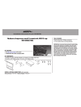
KIT FEATURES
• Double DIN Radio Provision
• Stacked ISO Mount Units Provision
A) Double DIN Trim Plate • B) Double DIN Brackets
KIT COMPONENTS
A
TOOLS REQUIRED:
1-800-221-0932
© COPYRIGHT 2004-2009 METRA ELECTRONICS CORPORATION
www.metraonline.com
B
Small Flat Blade Screwdriver/ Panel Removal Tool
• Phillips Screwdriver
WIRING AND ANTENNA CONNECTIONS
(Sold Separately)
Wiring Harness:
• 70-2105 - GM harness 2006-up
• 70-8405 - GM/Suzuki/Daewoo harness 1999-up
Antenna Adapter:
• 40-CR10 - Chryler antenna adapter 2002-up

Dash Disassembly
- Chevrolet Aveo
Hatchback 2007.....................
. . . . . .1
- Chevrolet Aveo
2004-2006 .........................
. . . . . .1
- Suzuki Forenza
2004-2008 / Suzuki Reno 2005-2008 .
. . . . . ..2
- Suzuki Verona
2004-2007 .........................
. . . . . . 3
- Pontiac G3 Hatchback 2007 .
.........................
. . . . . .1
Kit Assembly
- Double DIN Mount Radio Provision . . . .. . . . . . . . . . . . . . . . . . . . . . . . 4
- Stacked ISO Mount Units Provision . . . . . . . . . . . . . . . . . . . . . . . . . . 5
TABLE OF CONTENTS
95-7951
*Note:
Refer also to the instructions included with the aftermarket radio.
K
NOWLEDGE IS
P
OWER
Enhance your installation and fabrication skills by
enrolling in the most recognized and respected
mobile electronics school in our industry.
Log onto www.installerinstitute.com or call
800-354-6782 for more information and take steps
toward a better tomorrow.

95-7951 DASH DISASSEMBLY
CHEVROLET AVEO 2004-2006
B
1
1
Remove (4) Phillips screws securing
the radio. Unplug and remove radio.
(
Figure B)
Disconnect the negative battery ter-
minal to prevent an accidental short
circuit.
3
Unclip and remove the trim panels
from both sides of radio/climate con-
trols. (
Figure A)
2
Continue to kit assembly.
CHEVROLET AVEO HATCHBACK 2007
A
PONTIAC G3 HATCHBACK 2007

95-7951 DASH DISASSEMBLY
SUZUKI FORENZA 2004-2008
SUZUKI RENO 2005-2008
2
1
Open glove box and remove (5)
Phillips screws ((3) on top and (2) on
bottom) then remove entire glove box.
Disconnect the negative battery ter-
minal to prevent an accidental short
circuit.
3
Disconnect air selector cable on dri-
ver’s side of center console behind
dash above accelerator pedal.
(
Figure A & B)
2
4
Remove (4) 10 MM bolts securing
radio. Unplug and remove radio.
(
Figure E)
Disconnect temperature selector
cable on passenger side of center
console behind glove box. (
Figure C)
6
Unsnap and remove entire panel sur-
rounding radio. NOTE: The clips hold-
ing radio panel to dash are very
strong. (
Figure D)
5
Continue to kit assembly.
A
B
Inside of Glove Box
C
E
AM/FM
TAPE
CD
TUNE
1
2
3
4
5
6
BASS
MUTE
EQ
AST
SCAN
D

95-7951 DASH DISASSEMBLY
SUZUKI VERONA 2004-2007
A
B
3
1
Remove (4) Phillips screws from
radio. Unplug and remove radio.
(
Figure B)
Disconnect the negative battery ter-
minal to prevent an accidental short
circuit.
3
Unclip and remove the trim panel sur-
rounding the radio. (
Figure A)
2
Continue to kit assembly.

95-7951 KIT ASSEMBLY
4
DOUBLE DIN MOUNT RADIO PROVISION
CUT
HERE
ON BOTH SIDES
D
B
A
C
E
F
Snap the Double DIN brackets to the out-
side edge of the Double DIN trim plate.
(Figure E)
1
NOTE: For the Chevrolet Aveo 2004-06,
Chevrolet Aveo Hatchback 2007, Pontiac
G3 Hatchback 2007 and Suzuki Verona
2004-07, cut and remove front lower mount-
ing tabs from the Double DIN trim plate
(Figure A). For the Suzuki Forenza 2004-07 and
the Suzuki Reno 2005-07, cut the rear lower
mounting tabs (Figure B).
NOTE: The Verona 2004-2007 sub dash
will need to be trimmed slightly for proper
fit. Refer to illustration.
(Figure C,D)
Slide the Double DIN radio into the brack-
et/trim plate assembly and secure the
radio to the assembly using the screws
supplied with the radio.
(Figure F)
2
Continue to final assembly.
*
Note: Refer also to the instructions included with the aftermarket radio.

95-7951 KIT ASSEMBLY
5
STACKED ISO MOUNT UNITS PROVISION
*
Note: Refer also to the instructions included with the aftermarket radio.
E
F
Snap the Double DIN brackets to the out-
side edge of the Double DIN trim plate.
(Figure E)
1
Slide the stacked ISO units into the brack-
et/trim plate assembly and secure the units
to the assembly using the screws supplied
with the units.e
(Figure F)
2
Continue to final assembly.
NOTE: The Verona 2004-2007 sub dash will
need to be trimmed slightly for proper fit.
Refer to illustration.
(Figure C,D)
CUT
HERE
ON BOTH SIDES
D
C
B
A
NOTE: For the Chevrolet Aveo 2004-06,
Chevrolet Aveo Hatchback 2007, Pontiac
G3 Hatchback
2007 and Suzuki Verona
2004-07, cut and remove front lower mount-
ing tabs from the Double DIN trim plate
(Figure A). For the Suzuki Forenza 2004-07 and
the
Suzuki Reno 2005-07, cut the rear lower
mounting tabs (Figure B).

95-7951 FINAL ASSEMBLY
FINAL ASSEMBLY
(A) Strip wire ends back 1/2"
B) Twist ends together
C) Solder
D) Tape
A
B
C
D
Locate the factory wiring harness in the dash. Metra recommends using the
proper mating adapter and making connections as shown. (Isolate and individ-
ually tape off the ends of any unused wires to prevent electrical short circuit.)
Re-connect the negative battery terminal and test the unit for proper operation.
Reassemble radio and dash assemblies in reverse order of disassembly.
1
2
3
FINAL WIRING CONNECTIONS
Make wiring connections using the EIA color code chart shown below and the instructions included with the
head unit. Metra recommends making connections as shown below; Strip, Splice, Solder, Tape. Isolate and
individually tape off ends of any unused wires to prevent electrical short circuit.
METRA / EIA WIRING CODE
12V Ignition / Acc. . . . . . . . . . Red
12V Batt / Memory. . . . . . . . . Yellow
Ground. . . . . . . . . . . . . . . . . . Black*
Power Antenna. . . . . . . . . . . . Blue
Amp Turn-On . . . . . . . . . . . . . Blue / White
Amp Ground. . . . . . . . . . . . . . Black / White
Illumination . . . . . . . . . . . . . . Orange
Dimmer . . . . . . . . . . . . . . . . . Orange / White
Right Front (+) . . . . . . . . . . . . Gray
Right Front (-). . . . . . . . . . . . . Gray/ Black
Left Front (+) . . . . . . . . . . . . . White
Left Front (-). . . . . . . . . . . . . . White / Black
Right Rear (+) . . . . . . . . . . . . Violet
Right Rear (-) . . . . . . . . . . . . . Violet / Black
Left Rear (+) . . . . . . . . . . . . . Green
Left Rear (-) . . . . . . . . . . . . . . Green / Black
*NOTE: When a Black wire is not present, ground radio to vehicle chassis.
All colors may not be present on all leads due to manufacturer’s specifications.
1-800-221-0932
REV. 06/02/09 © COPYRIGHT 2004-2009 METRA ELECTRONICS CORPORATION INST95-7951
www.metraonline.com
/