
OWNER MANUAL
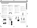
> Congratulations P. 2
> Bicycle safety P. 2
> Saddle height P. 3
> Suspension on Scott mountain bikes P. 3
> Gears P. 4
> Adjustment of the Index rear derailleur P. 4
> Adjutment of the front derailleur P. 5
> Chain maintenance P. 7
> Operation Rapid Fire Plus system P. 7
> Brakes P. 12
> Tires and rims P. 15
> Maintenance and care P. 16
> Bicycle care P. 18
> Tightening torques for Scott Bikes P. 19
> Trouble shooting P. 20
> Warranty P. 21
> Parts of wear and tear P. 22
> Protocol for handing over P. 24
Content
SCOTT BICYCLES
OWNER MANUAL
0-1
manual2_ A5 _Engl. 26.09.2003 16:29 Uhr Seite 2

Suspensions on SCOTT
Mountain Bikes
OWNER MANUAL
1. Obey all traffic laws,
2. Make sure that the bike size is right for the rider,
and that he can reach brake levers properly,
3. Make sure that the brakes and the bicycle work
perfectly well (cf maintenance),
4. Always have a light at night and install reflectors
properly,
5. Never ride two people on a bicycle designed for
one (except specially designed and properly instal
led child carriers.),
6. Never hitch a ride on another vehicle,
7. Do not weave or race in traffic,
8. Watch out for parked cars (door can be opened at
any time) and cars pulling into traffic,
9. Use proper signals when turning,
10. Mount loads securely. Never carry packages that
interfere with brakes or vision,
11. Always wear a helmet.
Congratulations on your purchase of a new SCOTT
bicycle! We are confident that the bicycle will exceed
your expectations for value, performance, and ride qua-
lity. Each frame set and component has been custom
specified and designed to enhance your riding experien-
ce. Whether you are a beginning cyclist, or a seasoned
pro. SCOTT bicycles will provide endless hours of two-
wheeled fun.
We strongly encourage you to take the time to read this
manual and familiarise yourself with your new bicycle.
If you have purchased a bike for your children, please
take the time to make sure they understand the infor-
mation contained in this Owner’s Manual.
Important!
If you purchased this bicycle for a minor, it is essential
that a responsible adult/parent thoroughly reviews and
reads the Owner’s Manual to the minor.
It is important to understand the basics of riding a
bicycle, but it is equally important to exercise common
sense when cycling. Cycling is a dynamic sport and
requires reacting to varying situations. Like any sports,
cycling involves risk of injury and damage. By choosing
to ride a bicycle, you assume the responsibility for that
risk.
If you have questions or problems regarding your new
SCOTT bicycle, please contact your Authorised Dealer.
Ride Frequently!
Congratulations! Bicycle safety
OWNER MANUAL
2-3
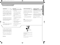
Comfortable riding not only depends on the position of
the saddle, but also on its height. You can accurately
adjust the height of the saddle to the length of your legs
when you proceed as follows:
1. Straddle the saddle. Place the ball of your foot on
the pedal nearest to the ground. Make sure the
cranks are vertical.
2. If the heel of your foot points down about 30
degrees, the height of the saddle is correct.
Caution!
Make sure that the limit mark on your seat post is insi-
de the seat tube. If it is not possible to reach the correct
seat height, you have to choose a size above.
If you need to change the inclination of the saddle or the
horizontal position, please make sure not to exceed the
max. tightening torque.
Screws with M5 should be tightened with 6 Nm, M8
with 20 Nm.
Please make sure the saddle is connected perfect with
the seat post before every ride.
If you have chosen a SCOTT bike equipped with a
suspension fork, please refer to the enclosed
instructions of the manufacturer.
For the adjustment of the rear suspension on a fully
suspension bike, please refer to the instructions of
the manufacturer of the suspension elements, and
to the SCOTT instructions for full suspension bikes.
Both booklets are enclosed with the bike.
Only a well adjusted suspension brings security,
comfort and fun.
Frame size and saddle height
Make sure that this part
remains in the seat tube
manual2_ A5 _Engl. 26.09.2003 16:29 Uhr Seite 4

All SCOTT bikes are fitted with a so-called index rear
derailleur. This derailleur can be positioned exactly
below the required sprocket through pre programmed
"clicking”. Changing gears is easy with the index sys-
tem, provided it is properly adjusted. Contrary to the
adjustment of any ordinary derailleur, the adjustment of
the index derailleur requires special attention and is
therefore best left to your SCOTT dealer. Should you
nevertheless want to adjust the index system yourself,
proceed as follows:
1. Change to the largest gear (smallest rear sprocket).
2. Drive the pedals forward a few times. In case of
chain noise, adjust the derailleur with the adjus-
ting screws.
3. Pull the derailleur control cable tight and secure it
with the cable screw in the rear derailleur to
tighten the cable screw even further.
4. Use the shift lever to change to the next sprocket.
There should be no chain noise. If necessary,
adjust the cable screw.
OWNER MANUAL
Introduction on derailleurs
The front and the rear derailleur have already been
adjusted by your SCOTT dealer. Therefore, no readjust-
ment will be necessary to begin with. However, it is
advisable to check the adjustment of the gear change
mechanism regularly.
When the gear lever is fully pushed towards the front,
the chain should be below the smallest or the biggest
sprocket.
When the adjustment of the derailleur is inaccurate, for
example when the chain is a little slack, it can jump off
either between the biggest sprocket and the spoke on
the left side and/or between the smallest sprocket and
the frame on the right side. This can lead to severe
damages and/or a fall.
The adjustment of the rear derailleur must not be too
slack (causing the chain to derail), nor too tight. In the
latter case, chain noise occurs when the chain is on the
smallest or largest sprocket. The stroke of the derailleur
can be limited both on the left and the right side by
means of two limit screws.
Changing gears Adjustment of the Index
rear derailleur
Adjustment of the Index rear
derailleur
Adjustment of the front derailleur
Usually, the front derailleur is secured to the seat
tube with a clamping strip, fitted with a bolt. As a
result the derailleur can be moved up/down and tur-
ned, the front derailleur can be adjusted in such a
way that the chain does not derail when the
derailleur is in its highest position. The derailleur
should not protrude beyond the largest chain wheel
by more than 2 mm and must not touch the pedal
crank. For correct adjustment proceed as follows.
OWNER MANUAL
4-5
1
12
2
1
2
12
2
1
Turn the adjustment screw so far to the right until chain jumps
back to second sprocket.
Loosen the screw so far to the left until chain touches the third
sprocket.
Pro-Set-Einstellblock
1 mm
3 mm
Zähne müssen
sich in diesem
Bereich befinden
Pro-Set-Lehre
Den Umwerfer wie in der Abbildung
gezeigt einstellen.
Der Pro-Set-Einstellblock darf noch
nicht entfernt werden.
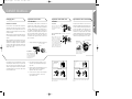
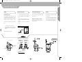
Top adjustment
Turn the top adjustment screw
to adjust so that the guide pul-
ley is in line with the outer line
of the smallest sprocket when
looking from the rear
Top adjustment screw
Outer line of smallest
sprocket
Guide pulley
Low adjustment
Turn the low adjustment screw so
that the guide pulley moves to a
position directly in line with the lar-
gest sprocket.
How to use the B-tension adjust-
ment screw
Mount the chain on the smallest
chainring and the largest sprocket,
and turn the crank arm backward.
Then turn the B-tension adjustment
screw to adjust the guide pulley as
close to the sprocket as possible but
not so close that it touches. Next, set
the chain to the smallest sprocket and
repeat the above to make sure that
the pulley does not touch the sprocket.
largest sprocket smallest sprocket
B-tension
adjustment screw
Low adjustment
screw
guide pulley
Largest
sprocket
adjustment screw
adjustment screw
in case of no
noise
If chain moves back
to third sprocket
pro set adjustment block
The derailleur must be adjusted as per
illustration. The pro-set adjustment
block may not be removed.
Sprocket teeths
must be set in this
position
manual2_ A5 _Engl. 26.09.2003 16:29 Uhr Seite 6

7
8
1
2
3
4
5
6
1
2
OWNER MANUAL
1. Mount the front derailleur on the seat tube
(without chain) and turn it in a temporary position,
2. Check that the chain guide does not protrude
beyond the largest chain wheel by more than
2 mm. The chain guide must not touch the chain
wheels
3. The chain guide must run parallel to the chain
wheels. Check above,
4. Tighten the frame bolt and change to the smallest
gear (smallest chain wheel, larger rear sprocket).
In this position, the chain must almost run against
the chain guide inner blade,
5. Tighten the front derailleur control cable and
secure with the pinch bolt,
6. Change to the highest gear (largest chain wheel,
smallest sprocket). In this position the chain must
almost run against the chain guide outer plate of
the right pedal crank,
7. Adjust both highest positions of the front
derailleur with the adjusting screws,
Chain maintenance / wear Operation Rapidfire plus system
8. Change the chain to the smallest and the largest
gear. In both gears, the front derailleur must
smoothly and immediately change the chain from
the smallest to the largest chain wheel and vice
versa.
Note: This procedure applies for both two and three-
ringed pedal cranks with round chain wheel.
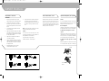
Caution!
To avoid excessive wear and damage of the chain,
sprockets and chain wheels, we advise against the fol-
lowing combinations (see illustrations):
Largest chain wheel – largest sprocket
Smallest chain wheel – smallest sprocket
Regularly check that your chain is clean and well-lubri-
cated. Have your dealer check the chain for wear.
Should you nevertheless want to check it yourself, you
need to purchase the Rohloff Chain Caliber 2 from your
SCOTT Dealer. This caliber will help you to work out
whether your chain is too slack of not.
Caution!
Do not press both right hand change control levers or
both left hand change control levers at the same time.
Damage to the change control may result.
Rear lever Operation
For both lever A and lever B, the lever always returns to
the initial position when it is released after changing.
To change from a small sprocket to a larger
sprocket
To change one gear step, press lever A to position 1; to
change two, three or four gear steps at one time, press
lever A to position 2, 3 or 4 respectively. A maximum of
four step change can be operated in this manner.
To change from a larger sprocket to a smaller
sprocket
When lever B is pulled once and is then released, there
is one step change from a large gear to a smaller gear.
OWNER MANUAL
6-7
Adjustment of the front
derailleur
Lever (A) starting
position
Lever (B)
manual2_ A5 _Engl. 26.09.2003 16:29 Uhr Seite 8

OWNER MANUAL
Front Lever operation
For both lever A and lever B, the lever always returns to
the initial position when it is released after changing.
To change from a small chain wheel to a larger
chain wheel
As is shown in the illustration, when lever A is pressed
to the mid-point of a full stroke, it clicks and there is a
change (of one gear) from a small chain wheel to the
next larger chain wheel.
Example: From the intermediate chain wheel to the lar-
gest chain wheel.
When the lever is pressed the full stroke (position 2),
there is a change from the smallest to the largest chain
wheel.
To change from a large chain wheel to a smaller chain
wheel.
When lever B is pushed once, there is a one step chan-
ge from a large chain wheel to a smaller chain wheel.
Example: From the largest chain wheel to the interme-
diate chain wheel.
Lever A to change from a small sprocket to a larger
sprocket.
Lever B to change from a large sprocket to a smaller
sprocket.
Lever a to change from a small chain wheel to a
larger chain wheel.
Lever b to change from a large chain wheel to
a smaller chain wheel.
All levers return to the initial position when released.
Levers:
Lever A
(Shift to larger chainring)
Lever A stops in positionen 1, 2 and 3.
Operation of rear derailleur levers
Lever A (to change from a small sprocket to a larger
sprocket)
Lever A has a click stop at positions 1, 2, and 3.
1. To change one gear at a time. Example: from
3rd to 4th.
2. To change two gears at a time. Example: from
3rd to 5th.
3. To change three gears at a time. Example:
from 3rd to 6th.
Lever B (to change from a large sprocket to a smal-
ler sprocket. When lever B is pressed once, there is
one step change from a large to a smaller
sprocket).
Operation of front derailleur levers
Lever a (to change from a small chain-ring to a
larger chain-ring).
If operation of lever a does not complete the chain
ring change stroke, operate lever A again for the
distance "X”.
Lever b (to change from a large sprocket to a smal-
ler sprocket. When lever B is pressed once, there is
one step change from a large to a smaller
sprocket).
When lever b is operated, there is one click where
trimming (the noise preventing mechanism) enga-
ges and a second stronger click when the gear
change stroke is completed. After trimming, the
next (light) push to the right will complete the gear
change stroke to the smaller front chain-ring.
Lever B (shift to smaller chainring)
OWNER MANUAL
8-9
Operation Rapidfire plus system
Hebel (A) Ausgangsstellung
Hebel (B)
Hebel B
Hinten Vorne
Hebel A
Hebel b
Hebel a
34
x
x'
Tatsächlich
erfolgter Zug
Hebel b
Startposition
Hebel b
Hebel AStartposition
Hebel A
Klickposition
Klickposition
Klickposition
4 3
35
3
6
Operation of Shimano Dual
Control System
Operation of Shimano Dual
Control System
To shift from a small chainring to a larger chainring
When Lever (A) is pressed once, ther is a shift of one step from a
small chainring to a larger chainring.
To shift from a large chainring to a smaller chainring
When lever (B) is pressed once, there is a shift of one step from a
large chainring to a smaller chainring.
Lever (A) initial position
Lever (B)
rear
lever b
lever a
lever b
lever a
front
lever B start position
lever B
start position
lever B
lever B
Example: Shift from
4th to third gear
lever
movement
click
lever a
shift one gear to next bigger
sprocket:
Example: Change from 3rd to
4th gear
shift two gears to bigger
sprocket:
Example: Change from 3rd to
5th gear
shift three gears to bigger
sprocket:
Example: Change from 3rd to
6th gear
initial
position
lever a click
click
Operation of rear derailleur lever
Lever A: Shifts from smaller to lager rear sprocket
Lever B: Stops at positions 1, 2 and 3
manual2_ A5 _Engl. 26.09.2003 16:29 Uhr Seite 10

OWNER MANUAL
If the chain is on the largest chain wheel and the largest
sprocket, the chain will rub against the front derailleur
plate. When this occurs, press lever b to the point
where it clicks, this causes the front derailleur to move
slightly towards the smaller chain wheel, thereby elimi-
nating the noise.
OWNER MANUAL
10-11
Trimming
(noise prevention mechanism)
Trimming
(noise prevention mechanism)
Chain
position Symptom
Trimming operation
Lever operation
Front derailleur movement
(Hits)
(Hits)
Lever (a)
Lever (b)
Click
Click
Chain
Outer plate
Front derailleur movement
Before trimming After trimming
trimming operation
Chain
Inner plate Front derailleur movement
Before trimming After trimming
trimming operation
Chain contacts
outer plate
Chain contacts
inner plate
Largest
chainring
Smaller
sprockets
Intermediate
chainring
Smaller
sprockets
Smallest
chainring
Smaller
sprockets
Largest chainring
Larger
sprockets
Intermediate
chainring
Larger
sprockets
Smallest
chainring
Larger
sprockets
manual2_ A5 _Engl. 26.09.2003 16:29 Uhr Seite 12

OWNER MANUAL
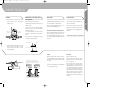
Brake adjustment general
Your SCOTT bike is fitted with a reliable and well-func-
tioning braking system, provided the brakes are correct-
ly adjusted. Check by measuring the distance between
the brake shoes and the rim: it should be 1.5 to 2 mm.
Cable connection and adjustment of the (Dual Pivot)
brake
1. Set the quick lever to the closed position.
2. Adjust the brake shoe clearance (as shown in the
illustration) and secure the cable with the pinch
bolt nut.
Cable bolt tightening torque 6-8 Nm
1. Loosen up the security screw with a 2 mm allen key.
2. Push the used brake pad out of the aluminium brake
shoe.
3. Push the new brake pad into the brake shoe, and
beware of the arrow which shows the mounting
direction.
4. Tighten up the security screw to approximately
1.5 Nm.
Make a minor adjustment by using the centring
adjustment screw.
Readjustment of the brake shoe clearance
Turn the cable-adjustment bolt to readjust the
brake shoe clearance.
1. While holding the shoe against the rim, tighten
the shoe fixing nut.
2. Pass the inner cable through the inner cable
lead, and after setting so that the total of the
clearances between the left and right shoes and
the rim is 2 mm tighten the cable fixing bolt.
OWNER MANUAL
12-13
Brakes Change of brake pads Centring the brake shoe V-Brake
2
Zentrierschraube
3mm-Inbusschlüssel
AB
+= 3 - 4 mm
221
1
offen
geschlossen
Schnellspannhebel
Schieben Sie den Bremsschuh zum Abnehmen aus der Bremsschuhhalternut.
Auf der rechten und linken Seite werden verschiedene Bremsschuhe und
Bremsschuhhalter verwendet. Schieben Sie den neuen Bremsschuh in die
Bremsschuhhalternut und achten Sie darauf, daß die Einschubrichtung und die
Schraubenlöcher richtig übereinstimmen.
Die Schraube wieder festziehen.
Die Schraube lösen.
Bremsschuh-
einschub-
richtung
für linke Seite für rechte Seite
gleich für vorne und hinten gleich für vorne und hinten
vorne vorne
Bremsschuh Bremsschuh Bremsschuhhalt
Bremsschuhhalter
Schraube
Schraube
2mm Inbusschlüssel
Schraube
Bremsschuh
Austauschen der Bremsschuheinheit
Anzugsdrehmoment: 1 - 1,5 Nm
Anzugsdrehmoment:
6 — 8 Nm
BC
B+C=2 mm
centering adjustment bolt
3mm allen key
open
closed
quick release lever
Replacement of the cartridge shoe
remove the set-
screw 2mm allen key
remove the shoe by sliding it along the groove of the shoe holder
set screw
shoe
There are two different types of shoe and shoe holder to be used in the left and
right positions respectively. Slide the new shoes into the grooves on the shoe
holders while taking note of the correct directions and screw hole positions.
for the left
front front
same at front and rear
shoe
shoe holder shoe holder
set screw
set screw
tighten the set screw
shoe
centering adjustment bolt
inner cable lead 5mm allen key
same at front and rear
for the right
shoe
insertion
direction
tightening torque: 1-1,5 Nm (9-13 in. lbs.)
tightening torque :
6-8 Nm (52-69 in. lbs.)
manual2_ A5 _Engl. 26.09.2003 16:29 Uhr Seite 14

OWNER MANUAL
3. Adjust the balance with the spring tension
adjustment screws.
Remove the security pin on the brake shoe.
1. Remove the brake pad by sliding it along the groove of
the brake shoe bar.
2. Make sure to use the correct brake pad and brake
shoe for each side. Those for the left side are different
from those for the right side.
3. Slide the new pad into the shoe and make sure that
the direction is correct and that the security pin holes
concord.
4. The insertion of the security fixing pin is very impor-
tant. It keeps the shoe properly in place
4. Depress the brake lever about 10 times as far as the
grip and check that everything is operating
correctly and that the shoe clearance is correct
before using the brakes.
If your bike is equipped with disc brakes, please refer to
the enclosed instructions of the manufacturer.
Please keep in mind that disc brakes need up to 30-100
brakings to reach maximum brake power.
Reasons for the reduction of the braking effects
When sudden braking in bad weather conditions, there
are risks of skidding. Even if this situation can be avoi-
ded, sudden braking will always happen. In this case,
we recommend to apply the rear brake a little more than
the front one.
Tires should always be inflated within the manu-
facture’s recommendations.
They are rated from 40 to 80 lbs. (check your tires).
Higher pressure for smoother roads or heavy riders.
Lower pressure for more shock absorption on rou-
gher terrains.
Fix a flat tire
Bike tires are fitted with tubes.
Remove the wheel from the bike and deflate it.
Unhook the tire from one side of the rim, using tire
tools, not screwdrivers.
Remove the tube from the tire casing, repair or
replace it. Install the new or repaired tire. Fill the
tube lightly with air in order to let it take its shape.
Put the valve stem through the hole, and fit the insi-
de tire. Put the tire bead in the rim starting at the
valve and finishing at the opposite end, working on
both sides. Push the valve stem into the tire and
pull it back down to seat. Make sure the tube is not
pinched under the tire bead. Inflate with hand or
foot-pump.
OWNER MANUAL
14-15
V-Brake Replacement of the brake pads/
cartridge shoe
Disc brakes Tires and Rims
Federeinstellschraube Federeinstellschraube
1 mm 1 mm
12
1 1
2 2
Bremshebel circa 10
mal anziehen
Remove the shoe fixing pin.
Remove the shoe by sliding it along the groove of the shoe holder.
shoe
shoe fixing pin
Insertion of shoe fixing pin is very critical to keep shoe properly fixed in place.
There are two different types of shoe and shoe holder to be used
in the left and right positions respectively. Slide the new shoes into the grooves
on the shoe holders while taking note of the correct directions and pin hole
positions.
Shoe
insertion
direction
for the left for the right
same at front and rear same at front and rear
front front
shoe holder shoe holder
shoe shoe
shoe fixing pin shoe fixing pin
Caution!
Whatever the weather is like, you will never exclusive-
ly need the front brake; in order to prevent from sliding,
you should always use both the front and the rear bra-
kes together.
By wet weather, the braking distance in approximately
60 % longer than by dry weather.
INFLATE TO MIN. 3.5 (50PSI) - MAX. 6.0 BAR (85PSI)
Spring tension
adjustment screw
Spring tension
adjustment screw
Depress lever about 10
times
manual2_ A5 _Engl. 26.09.2003 16:29 Uhr Seite 16

OWNER MANUAL
If the brake system has brake pads, you have to be
aware of the fact that the rim will be worn through the
action of braking.
When riding in wet and muddy terrain for example, the
rim is quickly worm out. SCOTT bikes that are fully
equipped (lights, mudguard, carrier) have a wear-out-
indicator.
Please refer to the enclosed instructions of the manu-
facturer.
– Front and rear derailleur for perfect function and
grease them. If necessary readjust the system
and clean it.
– The play of the headset. If necessary readjust it.
– Brake and shifting cables on perfect wear and
leakage on hydraulic systems. If necessary
grease the cables.
– chain wear and tension ( on bikes equipped with
internal gear hubs). Readjust if necessary, clean
and grease the chain.
– Bottom bracket cartridge for play, if necessary
replace it.
– Pedal bearings for play, if necessary replace them.
– front and rear derailleur for perfect function and
grease them. If necessary readjust the system and
clean it.
– stem and handlebar for visible damages and
replace them if necessary. Please make sure that
the bolts are tightened evenly when closing the
front cap, according to the tightening torque
recommended by the producer of the parts.
– Complete brake system on perfect function and
readjust and grease it if necessary. Replace worn
out or defective parts. Replace leaking hydraulic
pipelines at once .
– Rims and tension of spokes. If necessary true them.
– Air pressure of the tires according to the
recommendation of the producer.
– Overall condition of the tires
– Light systems and bell
– Handlebar grips to be fixed to the handlebar
– All parts of the rear suspension system including
mounting bolts
– The front suspension fork on perfect function and
play in the bushings.
– Frame and fork on perfect condition, replace in case
of damages
Maintenance schedule
Please be aware of the fact that you have to follow the
list of maximum tightening torques for screws at the
end of this chapter.
Please check before every ride:
– all bolts and nuts, especially the quick releases of
the wheels for proper fit and in case they are loose
tighten them according to the maximum tightening
torque.
– stem and handlebar for visible damages and
replace them if necessary. Please make sure that
the bolts are tightened evenly when closing the
front cap, according to the tightening torque
recommended by the producer of the parts.
– Braking systems
– Air pressure of the tires according to the
recommendation of the producer.
– Light systems and bell
– Handlebar grips to be fixed to the handlebar
OWNER MANUAL
16-17
Rim and wear of the rim Maintenance and Care Please check additionally
monthly:
Please check if necessary or at
least once a year at your dealer:
– All parts of the rear suspension system including
mounting bolts
– The front suspension fork on perfect function and
play in the bushings.
manual2_ A5 _Engl. 26.09.2003 16:29 Uhr Seite 18

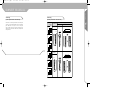
Mounting bolt
Cable fixing bolt
Pulley screws
Clamp
Cable fixing bolt
Clamp mounting bolt
Clamp mounting bolt
Clamp mounting bolt
Freewheel body
Cassette fixing nut
Square type
Spline type
Chainring screws
Mounting bolts M5
M6
M4
M5
M6
Frame mounting bolts
Cable fixing bolt
Brake pad bolts
Magura
Shimano
Formula
Hayes
Magura
Shimano
Formula
Hayes
Strike, G-Zero, Octane up from 2000,
High Octane
Intoxica
Octane up to 99
Tacoma
Strike, G-Zero, Octane up from 2000,
High Octane
Intoxica
Octane up to 99
Tacoma
All models
Rear Derailleur
Front Derailleur
Rapidfire lever
STI
Brake lever
Freewheel hub
Crankset
BB-Cartridge
Pedals
Stem
Seatpost-seatclamp
V-Brake
Caliper Disc brake
Disc mounting bolts
Swingarm pivot bolts
Rear shock mounting bolts
Replaceable Drop out
OWNER MANUAL
In order to keep the function and optic of the bike in
good condition we recommend periodical bicycle care.
Doing so keeps the value of the bike and helps to pre-
vent from corrosion or other damages:
- clean with soft brush, water and soft towel. Do not
use high pressure cleaner, otherwise bearings, color
or decals can be damaged.
- Do not use aggressive cleaning additives
- Repair color damages at once
- Grease or oil all metal parts especially during winter
use
- store the bike, especially in winter, in a dry room
- check the air pressure and put it to the recommended
pressure which can be seen on the sidewall of the
tire before storing longer times
OWNER MANUAL
18-19
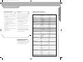
Bicycle care Tightening Torques for Scott Bikes
Please use biodegradable bicycle cleaners and de-
greasers which are offered at your local dealer.
Biodegradable bicycle cleaners
7.8-9.8 Nm
3.9-5.9 Nm
2.9-3.9 Nm
4.9-6.8 Nm
4.9-6.8 Nm
4.9-6.8 Nm
4.9-6.8 Nm
4.9-6.8 Nm
35-49 Nm
30-49 Nm
35-45 Nm
35-50 Nm
7.8-10.7 Nm
50-70 Nm
40 Nm
5.6-7.8 Nm
9.8-13.7 Nm
2.8-3.9 Nm
5.6-7.8 Nm
9.8-13.7 Nm
5-6.8 Nm
5.8-7.8 Nm
5-6.8 Nm
6 Nm
6-8 Nm
9 Nm
12 Nm
4 Nm
2-4 Nm
6.2 Nm
5 Nm
5 Nm
5.5 Nm
5.5 Nm
5.5 Nm
8 Nm
8 Nm
8 Nm
8 Nm
7.8-10.7 Nm
- chain wear and tension (on bikes equipped with
internal gear hubs). Readjust if necessary, clean and
grease the chain
- bottom bracket cartridge for play, if necessary replace it
- pedal bearings for play, if necessary replace them
- internal gear hub: check adjustment
- derailleur shifting system: check adjustment
- stem and handlebar for visible damages and replace
them if necessary
- complete brake system on perfect function and re-
adjust if necessary
- air pressure of the tires according to the recommen-
dation of the producer
- light systems and bell
Please check if necessary
manual2_ A5 _Engl. 26.09.2003 16:29 Uhr Seite 20

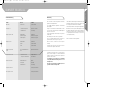
Troubleshooting
Trouble Reason Solution
Fork shakes headset loose tighten and lock
Chain pops out - derailleurs not adjusted adjust acc. to manual
- chainwheel bent fix or change
bearings squeak or crack bottom bracket replacement
pedals need grease dismount, clean, grease
hubs need grease dismount, clean, grease
bearings are loose bottom bracket replacement
pedals tighten and lock
hubs tighten and lock
handlebar cracks, shakes stem or handlebar bolts are tighten all bolts and nuts
or turns loose
seat post turns or slides - quick release is loose retighten and lock
- seat post too thin diameter check diameter
front derailleur rattles bottom bracket loose tighten
not adjusted adjust BB
chainwheel bent fix or change
suspension fork is loose contact your local dealer
rear suspension is loose contact your local dealer
OWNER MANUAL
OWNER MANUAL
20-21
The Scott bikes are made using the most innovative
production and quality methods.
It is equipped with best components of well known
parts suppliers.
Doing so Scott warrants its hardtail frames for three
years for defects in material and/or workmanship and
two years for Scott forks.
On other products/parts the warranty of the producer
remains valid.
The warranty period starts at the day of purchase.
In case of a warranty claim the decision to repair or to
replace the bike or defective part is up to Scott.
Wear and tear is not taken into account by the
warranty.
A complete list of all parts of wear and tear can be
found in the next chapter of this manual.
In addition you will find at the end of this manual a
protocol for the handing over of the bike which will
remain in copy at the Scott dealer after acceptance and
signature of the consumer.
It is obligatoy to show this protocol of handing
over together with the defective part in case of a
warranty claim.
It is your receipt of purchase and without, it is not
possible to make a warranty claim.
Claims must be made through an authorized dealer. For
information regarding the nearest dealer, write or call
this company or the national Scott distributor.
This warranty is limited to the original retail purchaser.
Normal wear, accident, neglect, abuse,improper assem-
bly, improper maintenance by other than an authorized
dealer or use of parts or devices not consistent with the
use originally intended for the bicycle as sold are not
covered by this warranty.
Under reservation of national legislation.
Warranty
manual2_ A5 _Engl. 26.09.2003 16:29 Uhr Seite 22

OWNER MANUAL
Chain
Due to its use the chain is subject to wear and tear. This
depends on maintenance and conditions of use of the bike
(amount of kilometers, rain, dirt, salt, etc.).
Cleaning and greasing will help to prolong its life but you
will have to replace the chain when reaching the wear limit.
Sprockets, chainrings and pulleys
Due to its use sprockets, chainrings and pulleys are subject
to wear and tear.
This depends on maintenance and conditions of use of the
bike (amount of kilometers, rain, dirt, salt, etc.).
Cleaning and greasing will help to prolong its life but you
will have to replace the chain when reaching the wear limit.
Shifting-and brake cables
All cables must be surveyed regularly and changed if neces-
sary. This can happen especially when the bike is often stan-
ding outside in weather.
Brakepads
All brake pads, no matter if rim-brake, disc-brake or internal
brake are subject to wear and tear due to their use.
This depends on maintenance and conditions of use of the
bike (amount of kilometers, rain, dirt, salt, etc.).
Check your brake pads regularly and replace them if neces-
sary.
Rims
When using a rim brake not only the brake pads are subject
to wear and tear. Also the rim.
Because of this please check regularly the rims e.g. when
inflating the tires.
In case of small cracks or deformation of the brake sur-
face of the rim while inflating the tires replace the rim
immediately.
Rims with wear-out indicators enable the bike user to
check easily the condition of the rim. Please have a
look concerning this issue on the sticker on the rim.
Tires
Due to their use tires are subject to wear and tear. This
depends on the use of the bike and is influenced by the
riding style.
Aggressive braking will reduce the lifetime of the tire
dramatically.
In addition check the air pressure regularly and inflate
the tire according to the pressure recommended by the
producer of the tire which is imprinted on the sidewall
of the tire.
Light Systems and reflectors
A well functioning light system is of a very high impor-
tance for your riding safety in public traffic.
Before every ride check front and tail light and the
condition of the reflectors.
Light bulbs are subject of wear and tear and we recom-
mend to take some replacements with you in case of
failure.
OWNER MANUAL
22-23
Parts of wear and tear
Handlebar grips
Due to their use handlebar grips are subject to wear and
tear, and should be replaced immediately in case they do not
fit anymore to the handlebar or get loosen.
Handlebar, stem and seat post
Handlebar, stem and seat post are under high dynamic for-
ces while riding.
Please check these parts regularly for visible cracks or
damages and replace them if necessary.
In addition we recommend a periodical replacement (every
two years) of these parts when riding often and hard.
Parts of wear and tear
manual2_ A5 _Engl. 26.09.2003 16:29 Uhr Seite 24

OWNER MANUAL
SCOTT Dealer
………………………………………………………............................
Address ………………………………………………………………………..
Telephone/Fax/e-mail: ………………………………………………………………………..
Consumer
Name ………………………………………………………………………
Address ………………………………………………………………………
Telephone/Fax/e-mail: ………………………………………………………………………
Product ………………………………………………………………………
Model ………………………………………………………………………
Date of delivery : ………………………………………………………………………
Confirmation
The product named above was checked detailed by myself:
The delivery took place completely and without any visible defects.
Notes : …………………………………………………………………………
……………………………………………………………………………………………….
The owner’s manual was handed over and I got a detailed oral information about its content.
I‘m aware that the duty for the implied warranty of the retailer is limited to faulty products. There
is no warranty for damages of wear and tear which are caused by using the product, especially when they
must be seen as normal wear and tear.
…………………………………………… ……………………………………………….
Place/date Consumer’s signature
OWNER MANUAL
24-25
Protocol for handing over
SCOTT Dealer
………………………………………………………............................
Address ………………………………………………………………………..
Telephone/Fax/e-mail: ………………………………………………………………………..
Consumer
Name ………………………………………………………………………
Address ………………………………………………………………………
Telephone/Fax/e-mail: ………………………………………………………………………
Product ………………………………………………………………………
Model ………………………………………………………………………
Date of delivery : ………………………………………………………………………
Confirmation
The product named above was checked detailed by myself:
The delivery took place completely and without any visible defects.
Notes : …………………………………………………………………………
……………………………………………………………………………………………….
The owner’s manual was handed over and I got a detailed oral information about its content.
I‘m aware that the duty for the implied warranty of the retailer is limited to faulty products. There
is no warranty for damages of wear and tear which are caused by using the product, especially when they
must be seen as normal wear and tear.
…………………………………………… ……………………………………………….
Place/date Consumer’s signature
Protocol for handing over
manual2_ A5 _Engl. 26.09.2003 16:29 Uhr Seite 26
-
 1
1
-
 2
2
-
 3
3
-
 4
4
-
 5
5
-
 6
6
-
 7
7
-
 8
8
-
 9
9
-
 10
10
-
 11
11
-
 12
12
-
 13
13


Ask a question and I''ll find the answer in the document
Finding information in a document is now easier with AI
Related papers
Other documents
-
 Pacific Cycle Mountain Bicycles; BMX Bicycles User manual
-
 Pacific Cycle Bicycle Owner's manual
-
 Avigo DUAL SUSPENSION MOUNTAIN BICYCLES User manual
-
 Stitch KM2002-1-JV Operating instructions
-
Infinity Mountain Bicycle Owner's manual
-
Apollo 2009 Owner's manual
-
-
Diamondback SHEPPARD CYCLES Owner's manual
-
-
Currier Tech Ezip Owner's manual


