
Motherboard
P7F-C Series
P7F-C/SAS
P7F-C/4L

ii
E5217
First Edition V1
December 2009
Copyright © 2009 ASUSTeK COMPUTER INC. All Rights Reserved.
No part of this manual, including the products and software described in it, may be reproduced, transmitted,
transcribed, stored in a retrieval system, or translated into any language in any form or by any means,
except documentation kept by the purchaser for backup purposes, without the express written permission
of ASUSTeK COMPUTER INC. (“ASUS”).
Product warranty or service will not be extended if: (1) the product is repaired, modified or altered, unless
such repair, modification of alteration is authorized in writing by ASUS; or (2) the serial number of the
product is defaced or missing.
ASUS PROVIDES THIS MANUAL “AS IS” WITHOUT WARRANTY OF ANY KIND, EITHER EXPRESS
OR IMPLIED, INCLUDING BUT NOT LIMITED TO THE IMPLIED WARRANTIES OR CONDITIONS OF
MERCHANTABILITY OR FITNESS FOR A PARTICULAR PURPOSE. IN NO EVENT SHALL ASUS, ITS
DIRECTORS, OFFICERS, EMPLOYEES OR AGENTS BE LIABLE FOR ANY INDIRECT, SPECIAL,
INCIDENTAL, OR CONSEQUENTIAL DAMAGES (INCLUDING DAMAGES FOR LOSS OF PROFITS,
LOSS OF BUSINESS, LOSS OF USE OR DATA, INTERRUPTION OF BUSINESS AND THE LIKE),
EVEN IF ASUS HAS BEEN ADVISED OF THE POSSIBILITY OF SUCH DAMAGES ARISING FROM ANY
DEFECT OR ERROR IN THIS MANUAL OR PRODUCT.
SPECIFICATIONS AND INFORMATION CONTAINED IN THIS MANUAL ARE FURNISHED FOR
INFORMATIONAL USE ONLY, AND ARE SUBJECT TO CHANGE AT ANY TIME WITHOUT NOTICE, AND
SHOULD NOT BE CONSTRUED AS A COMMITMENT BY ASUS. ASUS ASSUMES NO RESPONSIBILITY
OR LIABILITY FOR ANY ERRORS OR INACCURACIES THAT MAY APPEAR IN THIS MANUAL,
INCLUDING THE PRODUCTS AND SOFTWARE DESCRIBED IN IT.
Products and corporate names appearing in this manual may or may not be registered trademarks or
copyrights of their respective companies, and are used only for identification or explanation and to the
owners’ benefit, without intent to infringe.

iii
Contents
Notices ........................................................................................................ vii
Safety information .................................................................................... viii
About this guide ......................................................................................... ix
Typography .................................................................................................. x
P7F-C Series specications summary ...................................................... xi
Chapter 1: Product introduction
1.1 Welcome! ...................................................................................... 1-3
1.2 Package contents ......................................................................... 1-3
1.3 Serial number label ...................................................................... 1-4
1.4 Special features ............................................................................ 1-4
1.4.1 Product highlights ........................................................... 1-4
Chapter 2: Hardware information
2.1 Before you proceed ..................................................................... 2-3
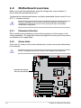
2.2 Motherboard overview ................................................................. 2-4
2.2.1 Placement direction ........................................................ 2-4
2.2.2 Screw holes .................................................................... 2-4
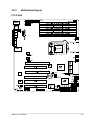
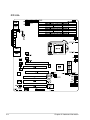
2.2.3 Motherboard layout ......................................................... 2-5
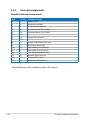
2.2.4 Layout contents ............................................................... 2-7
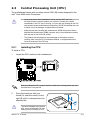
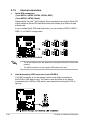
2.3 Central Processing Unit (CPU) ................................................... 2-9
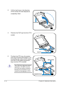
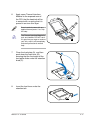
2.3.1 Installing the CPU ........................................................... 2-9
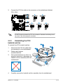
2.3.2 Installing the CPU heatsink and fan .............................. 2-12
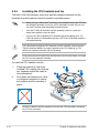
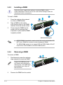
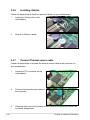
2.3.3 Uninstalling the CPU heatsink and fan ......................... 2-13
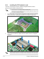
2.3.4 Installing the CPU heatsink in rack ............................... 2-14
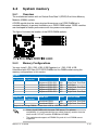
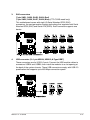
2.4 System memory ......................................................................... 2-15
2.4.1 Overview ....................................................................... 2-15
2.4.2 Memory Configurations ................................................. 2-15
2.4.3 Installing a DIMM .......................................................... 2-16
2.4.4 Removing a DIMM ........................................................ 2-16
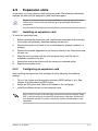
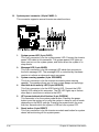
2.5 Expansion slots .......................................................................... 2-17
2.5.1 Installing an expansion card ......................................... 2-17
2.5.2 Configuring an expansion card ..................................... 2-17
2.5.3 Interrupt assignments ................................................... 2-18
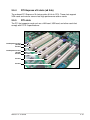
2.5.4 PCI Express x16 slots (x8 link) ..................................... 2-19
2.5.5 PCI slots ........................................................................ 2-19
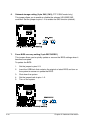
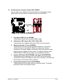
2.5.6 Installing i Button ........................................................... 2-20

iv
Contents
2.5.7 Connect Thermal sensor cable ..................................... 2-20
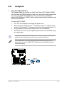
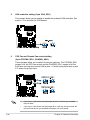
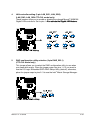
2.6 Jumpers ...................................................................................... 2-21
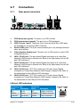
2.7 Connectors ................................................................................. 2-25
2.7.1 Rear panel connectors .................................................. 2-25
2.7.2 Internal connectors ....................................................... 2-26
Chapter 3: Powering up
3.1 Starting up for the rst time ........................................................ 3-3
3.2 Powering off the computer .......................................................... 3-4
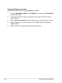
3.2.1 Using the OS shut down function .................................... 3-4
3.2.2 Using the dual function power switch .............................. 3-4
Chapter 4: BIOS setup
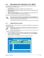
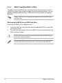
4.1 Managing and updating your BIOS ............................................ 4-3
4.1.1 ASUS EZ Flash 2 utility ................................................... 4-3
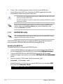
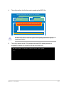
4.1.2 BUPDATER utility............................................................ 4-4
4.1.3 ASUS CrashFree BIOS 3 utility ...................................... 4-6
4.2 BIOS setup program .................................................................... 4-7
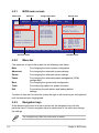
4.2.1 BIOS menu screen .......................................................... 4-8
4.2.2 Menu bar ......................................................................... 4-8
4.2.3 Navigation keys ............................................................... 4-8
4.2.4 Menu items ..................................................................... 4-9
4.2.5 Sub-menu items .............................................................. 4-9
4.2.6 Configuration fields ......................................................... 4-9
4.2.7 Pop-up window ............................................................... 4-9
4.2.8 Scroll bar ......................................................................... 4-9
4.2.9 General help ................................................................... 4-9
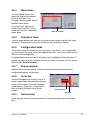
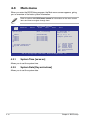
4.3 Main menu .................................................................................. 4-10
4.3.1 System Time [xx:xx:xx] ................................................. 4-10
4.3.2 System Date [Day xx/xx/xxxx] ....................................... 4-10
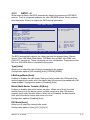
4.3.3 SATA1—6 .......................................................................4-11
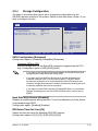
4.3.4 Storage Configuration ................................................... 4-13
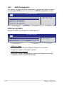
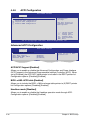
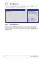
4.3.5 AHCI Configuration ....................................................... 4-14
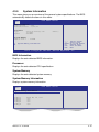
4.3.6 System Information ....................................................... 4-15
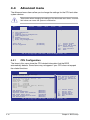
4.4 Advanced menu ......................................................................... 4-16
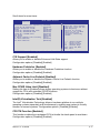
4.4.1 CPU Configuration ........................................................ 4-16
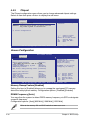
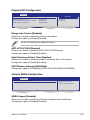
4.4.2 Chipset .......................................................................... 4-20

v
Contents
4.4.3 Onboard Devices Configuration .................................... 4-22
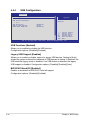
4.4.4 USB Configuration ........................................................ 4-24
4.4.5 PCIPnP ......................................................................... 4-25
4.4.6 ACPI Configuration ....................................................... 4-26
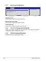
4.4.7 Event Log Configuration ............................................... 4-28
4.4.8 Intel VT-d Configuration [Disabled] ............................... 4-28
4.4.9 SR-IOV Supprted [Disabled] ......................................... 4-28
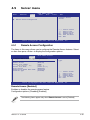
4.5 Server menu ............................................................................... 4-29
4.5.1 Remote Access Configuration ....................................... 4-29
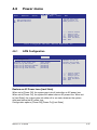
4.6 Power menu ................................................................................ 4-31
4.6.1 APM Configuration ........................................................ 4-31
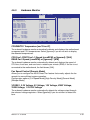
4.6.2 Hardware Monitor ......................................................... 4-33
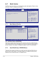
4.7 Boot menu .................................................................................. 4-34
4.7.1 Boot Device Priority ...................................................... 4-34
4.7.2 Hard Disk Drives; CDROM Drives ................................ 4-34
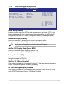
4.7.3 Boot Settings Configuration .......................................... 4-35
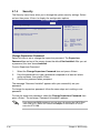
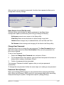
4.7.4 Security ......................................................................... 4-36
4.8 Tools menu ................................................................................. 4-38
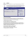
4.8.1 ASUS EZ Flash 2 .......................................................... 4-38
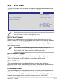
4.9 Exit menu .................................................................................... 4-39
Chapter 5: RAID conguration
5.1 Setting up RAID ............................................................................ 5-3
5.1.1 RAID definitions .............................................................. 5-3
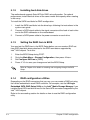
5.1.2 Installing hard disk drives ................................................ 5-4
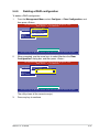
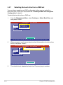
5.1.3 Setting the RAID item in BIOS ........................................ 5-4
5.1.4 RAID configuration utilities .............................................. 5-4
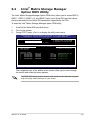
5.2 Intel® Matrix Storage Manager Option ROM Utility ................... 5-5
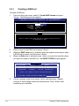
5.2.1 Creating a RAID set ........................................................ 5-6
5.2.2 Creating a Recovery set ................................................. 5-7
5.2.3 Deleting a RAID set ........................................................ 5-9
5.2.4 Resetting disks to Non-RAID ........................................ 5-10
5.2.5 Recovery Volume Options .............................................5-11
5.2.6 Exiting the Intel® Matrix Storage Manager .................... 5-12
5.2.7 Rebuilding the RAID ..................................................... 5-12
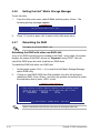
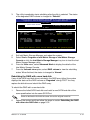
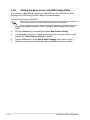
5.2.8 Setting the Boot array in the BIOS Setup Utility ............ 5-14
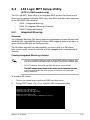
5.3 LSI Logic MPT Setup Utility (P7F-C/SAS model only) ............ 5-15

vi
Contents
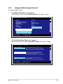
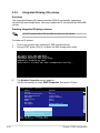
5.3.1 Integrated Mirroring ....................................................... 5-15
5.3.2 Integrated Mirroring Enhanced ..................................... 5-19
5.3.3 Integrated Striping (IS) volume ..................................... 5-22
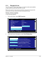
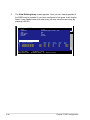
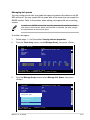
5.3.4 Managing Arrays ........................................................... 5-25
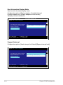
5.3.5 Viewing SAS topology ................................................... 5-30
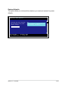
5.3.6 Global Properties .......................................................... 5-31
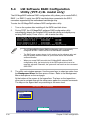
5.4 LSI Software RAID Conguration Utility
(P7F-C/4L model only) ............................................................... 5-34
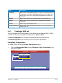
5.4.1 Creating a RAID set ...................................................... 5-35
5.4.2 Adding or viewing a RAID configuration ....................... 5-41
5.4.3 Initializing the virtual drives ........................................... 5-42
5.4.4 Rebuilding failed drives ................................................. 5-46
5.4.5 Checking the drives for data consistency ..................... 5-48
5.4.6 Deleting a RAID configuration ....................................... 5-51
5.4.7 Selecting the boot drive from a RAID set ...................... 5-52
5.4.8 Enabling WriteCache .................................................... 5-53
Chapter 6: Driver installation
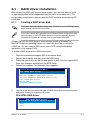
6.1 RAID driver installation ............................................................... 6-3
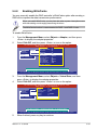
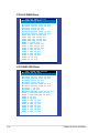
6.1.1 Creating a RAID driver disk ............................................ 6-3
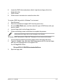
6.1.2 Installing the RAID controller driver ................................ 6-6
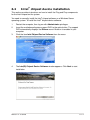
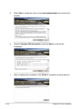
6.2 Intel® chipset device installation .............................................. 6-19
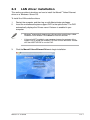
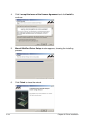
6.3 LAN driver installation ............................................................... 6-21
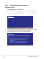
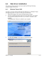
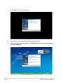
6.4 VGA driver installation............................................................... 6-23
6.4.1 Windows® Server 2003 ................................................. 6-23
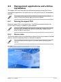
6.5 Management applications and utilities installation ................ 6-25
6.5.1 Running the support DVD ............................................. 6-25
6.5.2 Drivers menu ................................................................. 6-25
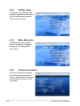
6.5.3 Utilities menu ................................................................ 6-26
6.5.4 Make disk menu ............................................................ 6-26
6.5.5 Contact information ....................................................... 6-26
Appendix: Reference information
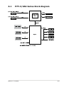
A.1 P7F-C/SAS Series block diagram ...............................................A-3
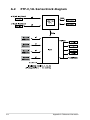
A.2 P7F-C/4L Series block diagram ..................................................A-4

vii
Notices
Federal Communications Commission Statement
This device complies with Part 15 of the FCC Rules. Operation is subject to the
following two conditions:
•
This device may not cause harmful interference, and
•
This device must accept any interference received including interference that
may cause undesired operation.
This equipment has been tested and found to comply with the limits for a
Class B digital device, pursuant to Part 15 of the FCC Rules. These limits are
designed to provide reasonable protection against harmful interference in a
residential installation. This equipment generates, uses and can radiate radio
frequency energy and, if not installed and used in accordance with manufacturer’
s instructions, may cause harmful interference to radio communications. However,
there is no guarantee that interference will not occur in a particular installation. If
this equipment does cause harmful interference to radio or television reception,
which can be determined by turning the equipment off and on, the user is
encouraged to try to correct the interference by one or more of the following
measures:
•
Reorient or relocate the receiving antenna.
•
Increase the separation between the equipment and receiver.
•
Connect the equipment to an outlet on a circuit different from that to which the
receiver is connected.
•
Consult the dealer or an experienced radio/TV technician for help.
Canadian Department of Communications Statement
This digital apparatus does not exceed the Class B limits for radio noise emissions
from digital apparatus set out in the Radio Interference Regulations of the
Canadian Department of Communications.
This class B digital apparatus complies with Canadian ICES-003.
The use of shielded cables for connection of the monitor to the graphics card is
required to assure compliance with FCC regulations. Changes or modifications
to this unit not expressly approved by the party responsible for compliance could
void the user’s authority to operate this equipment.
REACH
Complying with the REACH (Registration, Evaluation, Authorization, and Restriction
of Chemicals) regulatory framework, we published the chemical substances in our
products at ASUS REACH website at http://green.asus.com/english/REACH.htm.

viii
Safety information
Electrical safety
• To prevent electrical shock hazard, disconnect the power cable from the
electrical outlet before relocating the system.
• When adding or removing devices to or from the system, ensure that the
power cables for the devices are unplugged before the signal cables are
connected. If possible, disconnect all power cables from the existing system
before you add a device.
• Before connecting or removing signal cables from the motherboard, ensure
that all power cables are unplugged.
• Seek professional assistance before using an adapter or extension cord.
These devices could interrupt the grounding circuit.
• Make sure that your power supply is set to the correct voltage in your area.
If you are not sure about the voltage of the electrical outlet you are using,
contact your local power company.
• If the power supply is broken, do not try to fix it by yourself. Contact a
qualified service technician or your retailer.
Operation safety
• Before installing the motherboard and adding devices on it, carefully read all
the manuals that came with the package.
• Before using the product, make sure all cables are correctly connected and the
power cables are not damaged. If you detect any damage, contact your dealer
immediately.
• To avoid short circuits, keep paper clips, screws, and staples away from
connectors, slots, sockets and circuitry.
• Avoid dust, humidity, and temperature extremes. Do not place the product in
any area where it may become wet.
• Place the product on a stable surface.
• If you encounter technical problems with the product, contact a qualified
service technician or your retailer.
This symbol of the crossed out wheeled bin indicates that the product (electrical,
electronic equipment, and mercury-containing button cell battery) should not
be placed in municipal waste. Check local regulations for disposal of electronic
products.

ix
About this guide
This user guide contains the information you need when installing and configuring
the motherboard.
How this guide is organized
This user guide contains the following parts:
• Chapter 1: Product introduction
This chapter describes the features of the motherboard and the new
technologies it supports.
• Chapter 2: Hardware information
This chapter lists the hardware setup procedures that you have to perform
when installing system components. It includes description of the switches,
jumpers, and connectors on the motherboard.
• Chapter 3: Powering up
This chapter describes the power up sequence and ways of shutting down
the system.
• Chapter 4: BIOS setup
This chapter tells how to change system settings through the BIOS Setup
menus. Detailed descriptions of the BIOS parameters are also provided.
• Chapter 5: RAID conguration
This chapter provides instructions for setting up, creating, and configuring
RAID sets using the available utilities.
• Chapter 6: Driver installation
This chapter provides instructions for installing the necessary drivers for
different system components.
• Appendix: Reference information
This appendix includes additional information that you may refer to when
configuring the motherboard.
Where to nd more information
Refer to the following sources for additional information and for product and
software updates.
1. ASUS websites
The ASUS website provides updated information on ASUS hardware and
software products. Refer to the ASUS contact information.
2. Optional documentation
Your product package may include optional documentation, such as warranty
flyers, that may have been added by your dealer. These documents are not
part of the standard package.

x
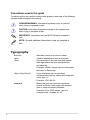
Conventions used in this guide
To make sure that you perform certain tasks properly, take note of the following
symbols used throughout this manual.
Typography
Bold text Indicates a menu or an item to select.
Italics Used to emphasize a word or a phrase.
<Key> Keys enclosed in the less-than and greater-
than sign means that you must press the
enclosed key.
Example: <Enter> means that you must press
the Enter or Return key.
<Key1+Key2+Key3> If you must press two or more keys
simultaneously, the key names are linked with
a plus sign (+).
Example: <Ctrl+Alt+D>
Command Means that you must type the command
exactly as shown, then supply the required
item or value enclosed in brackets.
Example: At the DOS prompt, type the
command line: format A:/S
DANGER/WARNING: Information to prevent injury to yourself
when trying to complete a task.
CAUTION: Information to prevent damage to the components
when trying to complete a task.
NOTE: Tips and additional information to help you complete a
task.
IMPORTANT: Instructions that you MUST follow to complete a
task.

xi
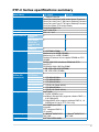
P7F-C Series specications summary
Model Name P7F-C/SAS P7F-C/4L
Processor / System Bus 1 * Socket LGA1156
Quad Core Intel Xeon 3400 series Server Processor
Quad Core Intel Core i7-800 series Desktop Processor
Quad Core Intel Core i5-700 series Desktop Processor
Dual Core 32nm CPU design Ready
Dual Core/Quad Core
Core Logic Intel® 3420 PCH
Form Factor ATX, 12" * 9.6"
ASUS Features FAN speed
control
V V
Rack Ready
(Rack and
Pedestal dual
use)
V V
ASWM2.0 V V
Memory Total Slots 6/4 (RDIMM/UDIMM)
Capacity Maximum up to 32GB (RDIMM)
Maximum up to 16GB (UDIMM )
Desktop Processor do not support RDIMM nor ECC
UDIMM
Memory Type DDR3 1066/1333 Unbuffered DIMM with ECC/
non ECC**
DDR3 800/1066/1333 Reg DIMM
Memory Size 1 GB, 2GB, 4GB, 8GB (RDIMM)
1 GB, 2GB, 4GB (UDIMM)
Expansion Slots
(follow SSI
Loacation #)
Total PCI/PCI-X/
PCI-E Slots
6 6
Slot Loacation 1 1 * PCI 32bit/33 MHz
Slot Loacation 2 1 * PCI 32bit/33 MHz
Slot Loacation 3 1 * PCI 32bit/33 MHz
Slot Loacation 4 1 * PCI-E x16 (Gen2 x8 link)
Slot Loacation 5 1 * PCI 32bit/33 MHz
Slot Loacation 6 1 * PCI-E x16 (Gen2 x8 link)
Storage SATA Controller Intel® 3420:
6* SATA2 300MB/s ports -
Intel Matrix Storage utility supports software RAID 0, 1,
10 & 5(Windows)
LSI MegaRAID driver supports software RAID 0, 1&
10(Windows & Linux) (P7F-C/4L only)
SAS Controller LSI 1068E 8-port SAS
controller:
LSI® Integrated RAID 0, 1,
1E support
—
Networking LAN 2 * Marvell® 8056 PCI-E
GbE LAN
4 * Marvell® 8056 PCI-E
GbE LAN
Graphic VGA XGI® Z9s DDR2 64MB

xii
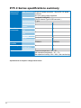
P7F-C Series specications summary
*Specications are subject to change without notice.
Onboard I/O
Connectors
PSU Connector 24-pin ATX power connector + 8-pin ATX 12V power
connector
24+4 pin power supply supported
USB Connectors 3 (support 5 USB port)
(One for internal Type A USB connector )
Fan Header 5* 4pin
Chassis Intruder 1 1
Serial Port
Header
1 1
Rear I/O
Connectors
External Serial
Port
1 1
External USB
Port
2 2
VGA Port 1 1
RJ-45 2 4
PS/2 KB/Mouse 1 1
Management
Solution
Software ASWM2.0 ASWM2.0
Monitoring CPU
Temperature
V V
FAN RPM V V
Environment Operation temperature: 10℃—35℃
Non operation temperature: -40℃—70℃
Non operation humidity: 20%—90% ( Non condensing)

1
Product
introduction
This chapter describes the motherboard
features and the new technologies it supports.

ASUS P7F-C Series
Chapter summary 1
1.1 Welcome! ...................................................................................... 1-3
1.2 Package contents ......................................................................... 1-3
1.3 Serial number label ...................................................................... 1-4
1.4 Special features ............................................................................ 1-4

ASUS P7F-C Series 1-3
1.1 Welcome!
Thank you for buying an ASUS® P7F-C Series motherboard!
The motherboard delivers a host of new features and latest technologies, making it
another standout in the long line of ASUS quality motherboards!
Before you start installing the motherboard, and hardware devices on it, check the
items in your package with the list below.
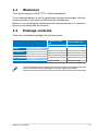
1.2 Package contents
Check your motherboard package for the following items.
If any of the above items is damaged or missing, contact your retailer.
Standard Gift Box
Pack Standard Bulk Pack
P7F-C Series
Cables SATA data cable 6 --
Accessories IO shield 1 1
Plate for LGA1156 (1U) 1 1
Application CD Support CD 1 1
Documentation User Guide 1 1
Packing Qty. 1pc per carton 10pcs per carton

1-4 Chapter 1: Product introduction
1.4 Special features
1.4.1 Product highlights
Intel® LGA1156 Xeon 3400 Processor Ready
This motherboard supports the latest Intel® Xeon 3400 processors in LGA1156
package, which has memory and PCI Express controller integrated to support
2-channel (6 DIMMs) DDR3 memory and 16 PCI Express 2.0 lanes, providing great
graphics performance. Intel® Xeon 3400 processor is one of the most powerful and
energy efficient CPU in the world.
Intel Turbo Boost
Intel® Turbo Boost opportunistically and automatically allows the processor to
run faster than the marked frequency if the processor is operating below power,
temperature and current limits. This technology increases performance of both
multi-threaded and single-threaded workloads.
Intel Hyper Threading
The thread-level parallelism on each processor makes more efficient use of the
processor resources, higher processing throughout and improved performance on
today's multi-threaded software.
Intel® EM64T
The motherboard supports Intel® processors with the Intel® EM64T (Extended
Memory 64 Technology). The Intel® EM64T feature allows your computer to run on
64-bit operating systems and access larger amounts of system memory for faster
and more efficient computing.
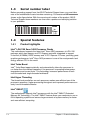
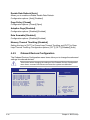
1.3 Serial number label
Before requesting support from the ASUS Technical Support team, you must take
note of the motherboard's serial number containing 13 characters xxS2xxxxxxxxx
shown as the figure below. With the correct serial number of the product, ASUS
Technical Support team members can then offer a quicker and satisfying solution
to your problems.
xxS2xxxxxxxxx
P7F-C Series Made
in
China
合格

ASUS P7F-C Series 1-5
DDR3 memory support
The P7F-C Series supports UDIMM and RDIMM DDR3 memory that features
data transfer rates of 1333/1066 MHZ to meet the higher bandwidth requirements
of server and workstation applications. The 2-channel DDR3 architecture boosts
system performance, eliminating bottlenecks. Furthermore, the supply voltage for
the memory is reduced from 1.8 V for DDR2 to just 1.5V for DDR3. This voltage
reduction limits the power consumption and heat generation of DDR3 which makes
it an ideal memory solution.
PCIe 2.0
This motherboard supports the latest PCIe 2.0 device for twice the current speed
and bandwidth. This enhances system performance while still providing backward
compatibility to PCIe 1.0 devices.
Marvell 88E8056 LAN Solution
The motherboard comes with dual/quad Gigabit LAN controllers and ports which
provide a total solution for your networking needs. The onboard Marvell 88E8056
Gigabit LAN controllers use the PCI Express interface and could achieve network
throughput close to Gigabit bandwidth.
Serial Attached SCSI (SAS) technology support
(P7F-C/SAS model only)
SAS is the latest storage interface for enterprise-class storage devices. Building
on and improving the parallel SCSI foundation, SAS is the new industry standard
that includes Serial ATA interoperability, and is projected to be the successor of the
Ultra320 SCSI technology.
Enhanced Intel SpeedStep Technology (EIST)
The Enhanced Intel SpeedStep Technology (EIST) intelligently manages the
CPU resources by automatically adjusting the CPU voltage and core frequency
depending on the CPU loading and system speed or power requirement.
Serial ATA II technology
The motherboard supports the Serial ATA II 3 Gb/s technology through the Serial
ATA interface and Intel 3420 chipset. The Serial ATA II specification provides
twice the bandwidth of the current Serial ATA products with a host of new
features, including Native Command Queuing (NCQ), Power Management (PM)
Implementation Algorithm, and Hot Swap. Serial ATA allows thinner, more flexible
cables with lower pin count and reduced voltage requirements.

1-6 Chapter 1: Product introduction
USB 2.0 technology
The motherboard implements the Universal Serial Bus (USB) 2.0 specification,
dramatically increasing the connection speed from the 12 Mbps bandwidth on USB
1.1 to a fast 480 Mbps on USB 2.0. USB 2.0 is backward compatible with USB 1.1.
Temperature, fan, and voltage monitoring
The CPU temperature is monitored to prevent overheating and damage. The
system fan rotations per minute (RPM) is monitored for timely failure detection.
The chip monitors the voltage levels to ensure stable supply of current for critical
components.

2
Hardware
information
This chapter lists the hardware setup
procedures that you have to perform
when installing system components. It
includes description of the jumpers and
connectors on the motherboard.

ASUS P7F-C Series
Chapter summary 2
2.1 Before you proceed ..................................................................... 2-3
2.2 Motherboard overview ................................................................. 2-4
2.3 Central Processing Unit (CPU) ................................................... 2-9
2.4 System memory ......................................................................... 2-15
2.5 Expansion slots .......................................................................... 2-17
2.6 Jumpers ...................................................................................... 2-21
2.7 Connectors ................................................................................. 2-25
Page is loading ...
Page is loading ...
Page is loading ...
Page is loading ...
Page is loading ...
Page is loading ...
Page is loading ...
Page is loading ...
Page is loading ...
Page is loading ...
Page is loading ...
Page is loading ...
Page is loading ...
Page is loading ...
Page is loading ...
Page is loading ...
Page is loading ...
Page is loading ...
Page is loading ...
Page is loading ...
Page is loading ...
Page is loading ...
Page is loading ...
Page is loading ...
Page is loading ...
Page is loading ...
Page is loading ...
Page is loading ...
Page is loading ...
Page is loading ...
Page is loading ...
Page is loading ...
Page is loading ...
Page is loading ...
Page is loading ...
Page is loading ...
Page is loading ...
Page is loading ...
Page is loading ...
Page is loading ...
Page is loading ...
Page is loading ...
Page is loading ...
Page is loading ...
Page is loading ...
Page is loading ...
Page is loading ...
Page is loading ...
Page is loading ...
Page is loading ...
Page is loading ...
Page is loading ...
Page is loading ...
Page is loading ...
Page is loading ...
Page is loading ...
Page is loading ...
Page is loading ...
Page is loading ...
Page is loading ...
Page is loading ...
Page is loading ...
Page is loading ...
Page is loading ...
Page is loading ...
Page is loading ...
Page is loading ...
Page is loading ...
Page is loading ...
Page is loading ...
Page is loading ...
Page is loading ...
Page is loading ...
Page is loading ...
Page is loading ...
Page is loading ...
Page is loading ...
Page is loading ...
Page is loading ...
Page is loading ...
Page is loading ...
Page is loading ...
Page is loading ...
Page is loading ...
Page is loading ...
Page is loading ...
Page is loading ...
Page is loading ...
Page is loading ...
Page is loading ...
Page is loading ...
Page is loading ...
Page is loading ...
Page is loading ...
Page is loading ...
Page is loading ...
Page is loading ...
Page is loading ...
Page is loading ...
Page is loading ...
Page is loading ...
Page is loading ...
Page is loading ...
Page is loading ...
Page is loading ...
Page is loading ...
Page is loading ...
Page is loading ...
Page is loading ...
Page is loading ...
Page is loading ...
Page is loading ...
Page is loading ...
Page is loading ...
Page is loading ...
Page is loading ...
Page is loading ...
Page is loading ...
Page is loading ...
Page is loading ...
Page is loading ...
Page is loading ...
Page is loading ...
Page is loading ...
Page is loading ...
Page is loading ...
Page is loading ...
Page is loading ...
Page is loading ...
Page is loading ...
Page is loading ...
Page is loading ...
Page is loading ...
Page is loading ...
Page is loading ...
Page is loading ...
Page is loading ...
Page is loading ...
Page is loading ...
Page is loading ...
Page is loading ...
Page is loading ...
Page is loading ...
Page is loading ...
Page is loading ...
Page is loading ...
Page is loading ...
Page is loading ...
Page is loading ...
Page is loading ...
Page is loading ...
Page is loading ...
Page is loading ...
Page is loading ...
Page is loading ...
Page is loading ...
Page is loading ...
Page is loading ...
Page is loading ...
Page is loading ...
-
 1
1
-
 2
2
-
 3
3
-
 4
4
-
 5
5
-
 6
6
-
 7
7
-
 8
8
-
 9
9
-
 10
10
-
 11
11
-
 12
12
-
 13
13
-
 14
14
-
 15
15
-
 16
16
-
 17
17
-
 18
18
-
 19
19
-
 20
20
-
 21
21
-
 22
22
-
 23
23
-
 24
24
-
 25
25
-
 26
26
-
 27
27
-
 28
28
-
 29
29
-
 30
30
-
 31
31
-
 32
32
-
 33
33
-
 34
34
-
 35
35
-
 36
36
-
 37
37
-
 38
38
-
 39
39
-
 40
40
-
 41
41
-
 42
42
-
 43
43
-
 44
44
-
 45
45
-
 46
46
-
 47
47
-
 48
48
-
 49
49
-
 50
50
-
 51
51
-
 52
52
-
 53
53
-
 54
54
-
 55
55
-
 56
56
-
 57
57
-
 58
58
-
 59
59
-
 60
60
-
 61
61
-
 62
62
-
 63
63
-
 64
64
-
 65
65
-
 66
66
-
 67
67
-
 68
68
-
 69
69
-
 70
70
-
 71
71
-
 72
72
-
 73
73
-
 74
74
-
 75
75
-
 76
76
-
 77
77
-
 78
78
-
 79
79
-
 80
80
-
 81
81
-
 82
82
-
 83
83
-
 84
84
-
 85
85
-
 86
86
-
 87
87
-
 88
88
-
 89
89
-
 90
90
-
 91
91
-
 92
92
-
 93
93
-
 94
94
-
 95
95
-
 96
96
-
 97
97
-
 98
98
-
 99
99
-
 100
100
-
 101
101
-
 102
102
-
 103
103
-
 104
104
-
 105
105
-
 106
106
-
 107
107
-
 108
108
-
 109
109
-
 110
110
-
 111
111
-
 112
112
-
 113
113
-
 114
114
-
 115
115
-
 116
116
-
 117
117
-
 118
118
-
 119
119
-
 120
120
-
 121
121
-
 122
122
-
 123
123
-
 124
124
-
 125
125
-
 126
126
-
 127
127
-
 128
128
-
 129
129
-
 130
130
-
 131
131
-
 132
132
-
 133
133
-
 134
134
-
 135
135
-
 136
136
-
 137
137
-
 138
138
-
 139
139
-
 140
140
-
 141
141
-
 142
142
-
 143
143
-
 144
144
-
 145
145
-
 146
146
-
 147
147
-
 148
148
-
 149
149
-
 150
150
-
 151
151
-
 152
152
-
 153
153
-
 154
154
-
 155
155
-
 156
156
-
 157
157
-
 158
158
-
 159
159
-
 160
160
-
 161
161
-
 162
162
-
 163
163
-
 164
164
-
 165
165
-
 166
166
-
 167
167
-
 168
168
-
 169
169
-
 170
170
-
 171
171
-
 172
172
-
 173
173
-
 174
174
-
 175
175
-
 176
176
-
 177
177
-
 178
178
-
 179
179
-
 180
180


Asus P7F-C User manual
- Category
- Server/workstation motherboards
- Type
- User manual
Ask a question and I''ll find the answer in the document
Finding information in a document is now easier with AI
Related papers
Other documents
-
Gigabyte GA-9ILDR Configuration Guide
-
ASRock Rack E3C256D4U-2L2T/BCM Installation guide
-
ASRock Rack SP2C621D32LM3 Installation guide
-
-
-
-
-
-
Broadcom EPYC3451D4U-2L2T2O8R User guide
-