Page is loading ...

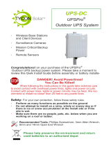
UPS-STL-600
UPSPro®
Backup Power System
▫ Wireless Base Stations
and Client Devices
▫ Surveillance Cameras
▫ Mission Critical Backup
Power
▫ Remote Sensors
Congratulations! on your purchase of the UPSPro® backup
power system. Please take a moment to review this Qwik Install
Guide before assembly or battery installation. Other instructions
come with other components of this kit. Be sure to review all in-
structions.
DANGER! Avoid Powerlines!
You Can Be Killed!
When following the instructions in this guide take extreme care
to avoid contact with overhead power lines, lights and power circuits.
Contact with power lines, lights or power circuits may be fatal. We rec-
ommend to install no closer than 20 feet to any power lines.
Safety: For your own protection, follow these safety rules.
▫ Perform as many functions as possible on the ground
▫ Do not attempt to install on a rainy, windy or snowy day or if
there is ice or snow accumulation at the install site or if the
site is wet.
▫ Make sure there are no people, pets, etc. below when you are
working on a roof or ladder.
Recommended Tools: Phillips & Flat Screwdriver, 17/13/10mm
wrench, 8mm nut driver
Please help preserve the environment and return
used batteries to an authorized depot. Most auto
parts stores will pay for your used battery.

2
Qwik Install
STEP 1: Prepare the enclosure: Install DIN rail (if required) to door
using two phillips head screws. Install just the top mounting bracket to
the enclosure using two 8mm bolts.
NOTE: It takes two people to mount the
enclosure to a pole. The standard U-Bolt
mounting accommodates a pole up to 4”
diameter. Multiple pole straps can be
used for extra strength. Pole straps are
available for poles to 11” diameter or
larger.
STEP 2: Install the bottom bracket and
stabilizer bracket to the pole using U-Bolt
and Pole Straps. The stabilizer bracket is
used as an aid to mounting and addition-
al support when mounted.
STEP 3: Lift the enclosure and place it
on the stabilizer bracket. Connect the top
bracket to the pole using U-Bolt and/or
Pole Straps.
STEP 4: Attach the two 8mm bolts that
hold the bottom bracket to the enclosure.
Make sure all bolts are tight. (8-15 ft lbs)
STEP 5: Install the three wire feedthru
cable glands in the holes in the bottom of
the enclosure.
NOTE: The bottom plate can be removed
from the enclosure if you need to add
some additional feedthru. (ex; conduit
connection)
STEP 6: Install the batteries in the en-
closure. For 12VDC, the batteries are
connected in parallel, for 24VDC, the
batteries are connected in series pairs. (See wiring diagrams later in
this guide).
NOTE: The enclosure has slot features that can be used
to strap the batteries if desired. Tycon has velcro straps
(#5700030) available. It takes two straps per battery.
STEP 7: Before attaching the battery cables to the batter-
ies, first remove the battery cable fuse. This will prevent
accidental short circuit.

3
Connect all battery minus (-) connections, then connect all battery plus
(+) connections. Because of high charging currents, two battery cables
are required for 12V installs.
NOTE: The fan supplied with the system operates on 12VDC or
24VDC. It is thermostatically controlled
to turn on if temperature exceeds 45C.
It can be connected directly to the bat-
teries or to the load output of the con-
troller.
STEP 8: Attach the black DIN Rail
adapters to the charge controller using
the screws provided. Clip the controller
to the DIN rail by putting the bottom of
the DIN bracket into the bottom of the
DIN rail, then push up and over the top
of the DIN rail.
STEP 9: Connect the battery wires to
the MPPT controller BAT inputs. Be
sure to pay strict attention to polarity.
Connect the 600W 48V battery charger
to the Solar Controller PV input (PV+ &
PV-). Make sure to observe proper polarity. Brown wire is V+. The con-
troller has a pluggable 3 wire AC cord. You can cut this cord to hardwire
into the mains. You can also mount conduit to the enclosure if local
codes require it.
CAUTION: Wiring with reverse polarity will cause equipment dam-
age. Don’t turn on 600W battery charger until MPPT controller has
been energized with battery power.
Important Note: The MPPT Controller ships with AUTO detection
of battery voltage enabled. We suggest changing this to a fixed 12V or
24V so that the system can recover automatically if, by chance, the bat-
teries get drained completely. See MPPT controller user manual for
specific instructions.
Double check wiring and then install the fuse in the battery cables to
energize the system. When a fully charged battery is connected, the
controller should power up and display the system parameters.
STEP 10: Mount any customer electronics to the inside of the enclo-
sure. Connect any loads to the Solar Controller LOAD output. (LOAD+
& LOAD-). Press red SET button to turn on/off the LOAD output.
STEP 11: Tighten all wire feedthrus. If they don’t tighten on a small
diameter wire, you can wrap some electrical tape around the wire in the
seal area to increase its diameter and make a better seal.

4
CAUTION: Be sure to connect
the battery to the controller first
and disconnect it last. Con-
necting PV connection to the
controller without the battery
connected could damage the
controller.
Note: There are multiple cable gland feedthrough in the bottom of the
enclosure. If you are not using any of the feedthrough you can cut a
short piece of wire, put it through the cable gland and tighten the cable
gland on the wire to seal it. When using 8 batteries, use the included
hole plug to close the hole under the 600W 48V battery charger.
STEP 12: Turn on the 600W 48V Battery Charger. During operation
the charger fan may run. This is normal.
STEP 13: Make sure the enclosure door gasket is clean, then close the
door making sure all wires are clear. The enclosure can be locked using
a standard combination or keyed padlock.
UPS-STL-600 4 Battery System

5
STEP 14: The UPSPro® is Solar Ready™ so a solar panel can be add-
ed to provide supplemental or full time power. The solar panel will be
connected to PV input (PV+ & PV-) in parallel with AC Battery Charger.
The solar panel PV+ must be connected to the solar controller through
an 80V-100V blocking diode (Tycon PN 5600059) to prevent reverse
current to the solar panel.
TECH CORNER
Additional Information you may find useful
1. CONTROLLER: The TP-SC24-40-MPPT controller is designed for
use with 12V or 24V battery systems. Maximum load output is 20A
Max.
2.Fuse: There is a fuse in-line in the battery cables. If fuse is blown
there was some sort of short in the battery connection and the controller
will appear dead. Replace with 3AG 6.3 x 32mm 30A Slo-Blo fuse.
3. VENTING: The enclosure is vented thru a thermostatically (45C)
controlled fan and top and bottom vents. The vents are covered with
dust/insect filters. You should add the checking/cleaning of the filters
UPS-STL-600 8 Battery System

6
Specifications UPS-STL-600
Battery Voltage (DC) 12V / 24V
Load Output Voltage (DC) 11-15V / 22-29V
Suggested Max Load 450W
AC Input Voltage 120/240VAC 50/60Hz 5A Max
Battery Charge Current 40A / 20A
Battery Charge Capacity 600W
Capacity (Ah) @ 12V 50Ah to 400Ah
Battery Type Valve Regulated Sealed Lead Ac-
id / Absorbent Glass Mat (AGM)
Battery Life 5 Years
Controller Type 40A MPPT with status display and
load control
Bulk Charge 14.4V / 28.8V
Float Charge 13.8V / 27.6V
Over-discharge protection 11V / 22V
Over-discharge recovery voltage 12.6V / 25.2V
Controller Self Consumption <1W
Maximum Solar Panel Size 520W / 1040W
Enclosure Type Powder Coat Steel
Operating Temperature -30°C to +60°C
System Weight (Without Batteries) 75lb (34kg)
Battery Weight (each) 37lb (17kg)
during any routine maintenance cycle but at least annually.
4. BATTERY MAINTENANCE: The batteries used in the Remote-
Pro® systems don’t require any maintenance. They should last up to 5
years in normal use. Note: Never store batteries for any length of
time in a discharged state or it may kill the battery. Always fully
charge before storage.
5. BATTERY OVERDISCHARGE: We highly recommend hooking all
equipment loads to the controller load outputs. This output will discon-
nect the loads if the battery voltage drops below the preset low voltage
disconnect level. This will protect the battery from over-discharge. If
batteries get completely discharged because the equipment was con-
nected directly to the battery, you will reduce the battery life and you

7
System Wiring Diagrams

8

9

10
Accessories
TP-SC-BT1 RS232 to Bluetooth adapter.
• Allows for wireless monitoring and con-
trol of the MPPT solar charge controller
up to 15m.
• Uses a smartphone app available for
Android and IOS devices
• Completely weatherproof for outdoor
mounting
• Low Cost
Notes

11
Remote Station Monitor
TPDIN-Monitor-WEB3
• Connects to Tycon MPPT controllers with
Modbus interface cable for automatic data
collection of PV, Battery and Load parame-
ters.
• Qty 4: Voltmeters and current meters
• Web Based: allows station monitoring over
the internet.
• Qty 4:10A relays for controlling power to de-
vices, starting a generator, etc.
• Measures internal and external temperatures
• Intuitive user interface and graphical setup
• SNMP compatability
• Shunt compatible for measuring very high
currents
• Email Alerts
• Programmable functionality
will most likely need to supercharge them with a good quality 10A auto-
motive battery charger. Once they are back to a normal operating
range, the integrated charge controller will maintain the charge. Don’t
charge batteries using an automotive charger for longer than 24hrs or
you may damage the battery.
Limited Warranty
The UPSPro® products are supplied with a limited 36 month warranty
which covers material and workmanship defects. This warranty does
not cover the following:
▫ Parts requiring replacement due to improper installation, misuse,
poor site conditions, faulty power, etc.
▫ Lightning or weather damage.
▫ Physical damage to the external & internal parts.
▫ Products that have been opened, altered, or defaced.
▫ Water damage for units that were not mounted according to user
manual.
▫ Usage other than in accordance with instructions and the normal
intended use.
Tycon Systems
14641 S 800 W
Bluffdale, UT 84065
support@tyconsystems.com
PH: 801-432-0003

12
/


