Page is loading ...

MANUAL NUMBER
CPrinted in Japan
ADVANTEST CORPORATION
All rights reserved.
R3765/67G Series
Network Analyzer
Operation Manual
FOE-8370681G01
1999 First printing December 1 1999
Applicable models
R3765AG
R3765BG
R3765CG
R3767AG
R3767BG
R3767CG
Cover

No. ESE00
Safety-1
Safety Summary
To ensure thorough understanding of all functions and to ensure efficient use of this instrument, please read the
manual carefully before using. Note that Advantest bears absolutely no responsibility for the result of operations
caused due to incorrect or inappropriate use of this instrument.
If the equipment is used in a manner not specified by Advantest, the protection provided by the equipment may
be impaired.
• Warning Labels
Warning labels are applied to Advantest products in locations where specific dangers exist. Pay
careful attention to these labels during handling. Do not remove or tear these labels. If you have
any questions regarding warning labels, please ask your nearest Advantest dealer. Our address
and phone number are listed at the end of this manual.
Symbols of those warning labels are shown below together with their meaning.
DANGER: Indicates an imminently hazardous situation which will result in death or serious
personal injury.
WARNING: Indicates a potentially hazardous situation which will result in death or serious
personal injury.
CAUTION: Indicates a potentially hazardous situation which will result in personal injury or
a damage to property including the product.
• Basic Precautions
Please observe the following precautions to prevent fire, burn, electric shock, and personal inju-
ry.
• Use a power cable rated for the voltage in question. Be sure however to use a power cable
conforming to safety standards of your nation when using a product overseas.
• When inserting the plug into the electrical outlet, first turn the power switch OFF and then
insert the plug as far as it will go.
• When removing the plug from the electrical outlet, first turn the power switch OFF and then
pull it out by gripping the plug. Do not pull on the power cable itself. Make sure your hands
are dry at this time.
• Before turning on the power, be sure to check that the supply voltage matches the voltage
requirements of the instrument.
• Be sure to plug the power cable into an electrical outlet which has a safety ground terminal.
Grounding will be defeated if you use an extension cord which does not include a safety
ground terminal.
• Be sure to use fuses rated for the voltage in question.
• Do not use this instrument with the case open.
Safety Summary

Safety Summary
Safety-2
• Do not place objects on top of this product. Also, do not place flower pots or other containers
containing liquid such as chemicals near this product.
• When the product has ventilation outlets, do not stick or drop metal or easily flammable ob-
jects into the ventilation outlets.
• When using the product on a cart, fix it with belts to avoid its drop.
• When connecting the product to peripheral equipment, turn the power off.
• Caution Symbols Used Within this Manual
Symbols indicating items requiring caution which are used in this manual are shown below to-
gether with their meaning.
DANGER: Indicates an item where there is a danger of serious personal injury (death or seri-
ous injury).
WARNING: Indicates an item relating to personal safety or health.
CAUTION: Indicates an item relating to possible damage to the product or instrument or relat-
ing to a restriction on operation.
• Safety Marks on the Product
The following safety marks can be found on Advantest products.
: ATTENTION - Refer to manual.
: Protective ground (earth) terminal.
: DANGER - High voltage.
: CAUTION - Risk of electric shock.

Safety Summary
Safety-3
• Replacing Parts with Limited Life
The following parts used in the instrument are main parts with limited life.
Replace the parts listed below after their expected lifespan has expired.
Note that the estimated lifespan for the parts listed below may be shortened by factors such as
the environment where the instrument is stored or used, and how often the instrument is used.
There is a possibility that each product uses different parts with limited life. For more informa-
tion, refer to Chapter 1.
Main Parts with Limited Life
• Precautions when Disposing of this Instrument
When disposing of harmful substances, be sure dispose of them properly with abiding by the
state-provided law.
Harmful substances: (1) PCB (polycarbon biphenyl)
(2) Mercury
(3) Ni-Cd (nickel cadmium)
(4) Other
Items possessing cyan, organic phosphorous and hexadic chromium
and items which may leak cadmium or arsenic (excluding lead in sol
der).
Example: fluorescent tubes, batteries
Part name Life
Unit power supply 5 years
Fan motor 5 years
Electrolytic capacitor 5 years
LCD panel 6 years
LCD backlight 2.5 years
Floppy disk drive 5 years

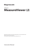
Environmental Conditions
Safety-4
This instrument should be only be used in an area which satisfies the following conditions:
• An area free from corrosive gas
• An area away from direct sunlight
• A dust-free area
• An area free from vibrations
Figure-1 Environmental Conditions
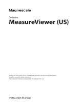
• Instrument Placement
Figure-2 Instrument Placement
This instrument can be used safely under the following conditions:
• Altitude of up to 2000 m
• Installation Categories II
• Pollution Degree 2
Vibration
Direct sunlight
Corrosive
gas
Dust
Front
Keep at least 10 centimeters of space
between the rear panel and any other
surface

Certificate of Conformity
This is to certify, that
complies with the provisions of the EMC Directive 89/336/EEC in accordance with
EN50081-1 and EN50082-1 and Low Voltage Directive 73/23/EEC in accordance with
EN61010.
ADVANTEST Corp. ROHDE&SCHWARZ
Tokyo, Japan Engineering and Sales GmbH
Munich, Germany
instrument, type, designation
3765.02
Network Analyzer
R3765AG, R3765BG, R3765CG,
R3767AG, R3767BG, R3767CG
Certificate of Conformity

R3765/67G Series Network Analyzer Operation Manual
Preface-1
PREFACE
<In the Beginning>
This manual explains all processes from the acceptance to actual operation of network analyzer
R3765/67G series. The manual of three volumes related about the R3765/67G series is shown in
the following.
<Caution>
ADVANTEST reserves the right to change the content of this manual and other product information
without notice.
Do not reproduce and do not reprint all of this manual or part without permission ADVANTEST
Corporation.
The address and the telephone number of ADVANTEST Corporation are described in the end of
this manual. Refer for the inquiry etc.
Manual name Model Strong points Remarks
R3765/67G Series
Network Analyzer
Operation Manual
(this manual)
R3765AG
3.8GHz modelR3765BG Bridge is built in.
R3765CG S parameter is built in.
R3767AG
8.0GHz modelR3767BG Bridge is built in.
R3767CG S parameter is built in.
R3764/65/66/67H Series
R3765/67G Series
Network Analyzer
Programming Manual
(separate volume)
This manual is shared between all models of R3765/67G series.
R3752/53/64/65/66/67G Series
R3765/67G Series
R3754 Series
Network Analyzer
Programming Guide
(separate volume)
This manual is shared between all models of R3765/67G series.
PREFACE

R3765/67G Series Network Analyzer Operation Manual
Preface
Preface-2
<How to Read this Manual>
(1) Distinction of panel key and soft key in this manual.
Panel key : (Example) [CH 1] , [5]
Soft key : (Example) {POWER}, {LOG MAG}

R3765/67G Series Network Analyzer Operation Manual
Preface
Preface-3
(2) Organization of this manual
Configuration Contents Remarks
Preface For the first use.
Confirmation of the products and the attachments. Read before first
use.
Contents Table of Contents, Figures, Tables
The configuration and the page of the description. Use to find
necessary
information easily.
1. GETTING STARTED
From setting to setup, cautions, cleaning,
transportation and storage.
Read before first
use.
2. Explanation of panel side and display screen
Name of each device, function and operation.
Description of display screen. Usage of the R3765/
67G series can be
understood by
reading it through.
3. Basic operating guidelines
Actual example of operation.
How to look at the display screen.
4. Basic operation
Description of the basic items.
Chapters of practice.
5. Measurement method example
Concrete examples and operational procedures.
6. Record and output
Saving to floppy disk and replaying.
7. Description of the functions
Detailed explanation of each block.
Refer if necessary.
8. In abnormal
Diagnostics and error message.
9. Operating principles
Basic operation and flow chart.
10. Performance test
11. Specifications
Technical information and general information.
Appendix Relation of data between each function
Initial setting.
Soft key menu list.
Other information.
Others DIMENSIONAL OUTLINE DRAWING Use to find the outer
dimensions.
Index Main words and the description page. Use to find
necessary
information easily.

TABLE OF CONTENTS
R3765/67G Series Network Analyzer Operation Manual
C-1
1 GETTING STARTED .......................................................................... 1-1
1.1 Product Description ................................................................................ 1-1
1.2 Product and Attachment ......................................................................... 1-2
1.3 Option, Accessory and Recommended Kit (Extra-cost) ......................... 1-3
1.4 Environmental Conditions ...................................................................... 1-5
1.5 Supply Description ................................................................................. 1-7
1.5.1 Power Supply Specifications............................................................. 1-7
1.5.2 Replacing the Power Fuse................................................................ 1-7
1.5.3 Connecting the Power Cable ............................................................ 1-8
1.6 System Setup Cautions .......................................................................... 1-9
1.6.1 Notes on the use of Parallel I/O Ports............................................... 1-9
1.6.2 Notes on the use of Serial I/O ports.................................................. 1-9
1.6.3 Note on the Probe Connector ........................................................... 1-9
1.7 Measurement Time ................................................................................ 1-9
1.8 Input Signal Level Overload Cautions .................................................... 1-9
1.9 How to Replace the Protective Fuse for Bias Input ................................ 1-10
1.10 Cleaning, Storage and Transportation ................................................... 1-11
1.11 Notes on Use ......................................................................................... 1-12
1.12 Calibration .............................................................................................. 1-14
1.13 Replacing Parts with Limited Life ........................................................... 1-14
2 PANEL DESCRIPTION ...................................................................... 2-1
2.1 Front Panel Descriptions ........................................................................ 2-1
2.1.1 R3765AG/67AG................................................................................ 2-1
2.1.2 R3765BG/67BG................................................................................ 2-3
2.1.3 R3765CG/67CG................................................................................ 2-5
2.1.4 R3765CG/67CG (OPT11)................................................................. 2-7
2.1.5 R3765CG/67CG (OPT14)................................................................. 2-9
2.2 Rear Panel Descriptions ........................................................................ 2-11
2.3 Screen Display Descriptions .................................................................. 2-13
3 BASIC OPERATING GUIDELINES ................................................ 3-1
3.1 Initial Power-on ...................................................................................... 3-1
3.2 Operation Keys ...................................................................................... 3-3
3.2.1 Panel Keys and Soft Keys................................................................. 3-3
3.3 How to Read the Display Screen ........................................................... 3-7
3.4 Basic Measuring Procedure ................................................................... 3-8
3.5 Measurement Samples of Simple Transmission Characteristics ........... 3-9
3.5.1 Setup and Setting.............................................................................. 3-9
3.5.2 Calibration (Normalize)..................................................................... 3-11
3.5.3 Magnitude measurement .................................................................. 3-12
TABLE OF CONTENTS

R3765/67G Series Network Analyzer Operation Manual
Table of Contents
C-2
3.5.4 Phase measurement......................................................................... 3-15
3.5.5 Group delay measurement................................................................ 3-17
3.6 Measurement Samples of Simple Reflection Characteristics ................ 3-20
3.6.1 Setup................................................................................................. 3-20
3.6.2 Calibration (1-port full calibration)..................................................... 3-22
3.6.3 Measurement by various formats...................................................... 3-25
4 BASICS OPERATION ........................................................................ 4-1
4.1 Basic Keys Operations ........................................................................... 4-1
4.2 Basic Key Operation Examples .............................................................. 4-1
4.3 Soft Key Menu Configuration ................................................................. 4-2
4.4 Initial Setup ............................................................................................ 4-3
4.4.1 How to Initialize................................................................................. 4-3
4.4.2 Initial Setup Value............................................................................. 4-3
4.5 Setting Backup Memory (Factory Default Settings) ............................... 4-7
5 MEASUREMENT METHOD EXAMPLE ......................................... 5-1
5.1 Measurement of Transmission Characteristic (2 Trace Display) ........... 5-1
5.1.1 Overlap Display Mode (Two Traces per Screen Measurement)....... 5-1
5.1.2 Split Display ...................................................................................... 5-6
5.2 Transmission/Reflection Characteristic Measurement
(Four Screen Display Mode) .................................................................. 5-10
5.2.1 Setup................................................................................................. 5-10
5.2.2 Calibration (two port full calibration).................................................. 5-11
5.2.3 Four Screen Display.......................................................................... 5-19
5.3 Narrow Band/Wide Band Sweep Measurement ..................................... 5-25
5.4 Multi-marker List Display ........................................................................ 5-28
5.5 Ripple Measurement in the Bandwidth .................................................. 5-31
5.6 Measurement of Electrical Length .......................................................... 5-36
5.7 High-speed Measurement Using the Program Sweep Function ............ 5-40
5.8 GO/NG Measurement Using Limit Line Function ................................... 5-45
6 RECORD and OUTPUT ..................................................................... 6-1
6.1 Output of Measured Data to the Plotter ................................................. 6-1
6.2 Using the Save/Recall Register ............................................................. 6-5
6.3 Saving to the Floppy Disk ...................................................................... 6-7
6.3.1 About the Measurement Data to Save.............................................. 6-9
7 FUNCTION DESCRIPTIONS ........................................................... 7-1
7.1 ACTIVE CHANNEL Block ...................................................................... 7-1
7.2 ENTRY Block ......................................................................................... 7-3
7.3 STIMULUS Block ................................................................................... 7-5

R3765/67G Series Network Analyzer Operation Manual
Table of Contents
C-3
7.3.1 Setting Signal Source........................................................................ 7-6
7.3.2 Interlocking between Channels......................................................... 7-8
7.4 RESPONSE Block ................................................................................. 7-9
7.4.1 Setting Input and Parameter Conversion.......................................... 7-10
7.4.2 Display Data Format ......................................................................... 7-14
7.4.3 Setting Display Coordinate Scale...................................................... 7-15
7.4.4 Four Screen Display and Display Selection Information................... 7-16
7.4.5 Display Layout................................................................................... 7-18
7.4.6 Trace Data Selection......................................................................... 7-23
7.4.7 TRACE Operation............................................................................. 7-24
7.4.8 Label Input........................................................................................ 7-25
7.4.9 Colors Settings.................................................................................. 7-26
7.4.10 Averaging/Smoothing and Resolution Bandwidth............................. 7-28
7.5 Calibration .............................................................................................. 7-31
7.5.1 Normalizing....................................................................................... 7-31
7.5.2 Normalize & Isolation Calibration...................................................... 7-32
7.5.3 1-Port Full Calibration ....................................................................... 7-32
7.5.4 2-Port Full Calibration (R3765CG/67CG only).................................. 7-34
7.5.5 Calibration Method............................................................................ 7-36
7.5.6 Interpolating Calibration Data............................................................ 7-42
7.5.7 Calibration Kit Selection.................................................................... 7-43
7.5.8 Parameters Entry of an User-selected Calibration Kit....................... 7-44
7.5.9 Extending Measurement Reference Plane ....................................... 7-47
7.5.10 Calibration Data Clear....................................................................... 7-50
7.5.11 3-Port Full Calibration....................................................................... 7-51
7.5.12 4-Port Full Calibration....................................................................... 7-58
7.6 Marker Function ..................................................................................... 7-64
7.6.1 Setting Marker................................................................................... 7-65
7.6.2 Marker Coupling between Channels................................................. 7-66
7.6.3 Interpolation between Measurement Points...................................... 7-68
7.6.4 Displaying Marker Read out Value.................................................... 7-68
7.6.5 Delta-Marker Function....................................................................... 7-69
7.6.6 Marker Menu during Impedance Measurement................................ 7-72
7.6.7 Marker Analysis Function.................................................................. 7-73
7.7 Time Domain Function(OPT 70) ............................................................ 7-84
7.7.1 Time Domain Transformation Function............................................. 7-84
7.7.2 Window Processing........................................................................... 7-86
7.7.3 Gate Function.................................................................................... 7-87
7.7.4 Time Domain Transformation Mode.................................................. 7-88
7.7.5 Transformation of the Time Domain Horizontal Axis......................... 7-88
7.8 CDMA IF Filter Analysis Function .......................................................... 7-89
7.9 Sweep .................................................................................................... 7-93
7.9.1 Setting Sweep Type.......................................................................... 7-93
7.9.2 Editing Segment of User Frequency Sweep..................................... 7-94

R3765/67G Series Network Analyzer Operation Manual
Table of Contents
C-4
7.9.3 Editing Segment of Program Sweep................................................. 7-95
7.10 Software Fixture Function (OPT 71/72) ................................................. 7-98
7.10.1 Overview........................................................................................... 7-98
7.10.2 Function ............................................................................................ 7-99
7.10.3 Measurement Example..................................................................... 7-119
7.11 INSTRUMENT STATE Block ................................................................. 7-127
7.11.1 System Menu.................................................................................... 7-128
7.11.2 System Configuration........................................................................ 7-130
7.11.3 Service Function ............................................................................... 7-131
7.12 Limit Function ......................................................................................... 7-132
7.12.1 Limit Menu......................................................................................... 7-132
7.13 GPIB Block ............................................................................................. 7-138
7.13.1 Controller Menu................................................................................. 7-139
7.13.2 GPIB Menu........................................................................................ 7-140
7.14 Save/Recall ............................................................................................ 7-141
7.14.1 Selection of Save Type..................................................................... 7-141
7.14.2 Executing Save Register................................................................... 7-142
7.14.3 Executing Store File.......................................................................... 7-144
7.14.4 Setting Register Name...................................................................... 7-145
7.14.5 Setting File Name.............................................................................. 7-146
7.14.6 Clearing Saved Register................................................................... 7-147
7.14.7 Purging Stored File ........................................................................... 7-148
7.14.8 Executing Recall............................................................................... 7-148
7.15 Hard Copy .............................................................................................. 7-151
7.15.1 Setting Plot Scale.............................................................................. 7-152
7.15.2 Selecting Plot Data............................................................................ 7-153
7.15.3 Specifying Pen.................................................................................. 7-153
7.15.4 Plotter Setup ..................................................................................... 7-154
7.15.5 Printer Setup..................................................................................... 7-156
7.15.6 Bitmap File Setup.............................................................................. 7-158
7.16 Communication with Peripheral Devices ................................................ 7-159
7.16.1 Parallel I/O Port................................................................................. 7-159
7.16.2 RS-232 Interface............................................................................... 7-168
8 IN ABNORMALITIES .......................................................................... 8-1
8.1 Inspection and Simple Troubleshooting ................................................. 8-1
8.2 Error Messages ...................................................................................... 8-2
8.2.1 Hardware Trouble............................................................................. 8-2
8.2.2 Notice of Hardware Information ........................................................ 8-3
8.2.3 Operating Error................................................................................. 8-4
8.2.4 Warning of Internal Set, Change, etc................................................ 8-9
8.2.5 Completed Operation Conditions Messages..................................... 8-12

R3765/67G Series Network Analyzer Operation Manual
Table of Contents
C-5
9 PRINCIPLE ........................................................................................... 9-1
9.1 Principle ................................................................................................. 9-1
9.2 Data Flow ............................................................................................... 9-2
10 PERFORMANCE TEST ..................................................................... 10-1
10.1 Preparing for a Performance Test .......................................................... 10-1
10.1.1 Warm up............................................................................................ 10-1
10.1.2 Preparing Measurement Instrument.................................................. 10-1
10.1.3 General Note..................................................................................... 10-3
10.2 Frequency Accuracy and Range ............................................................ 10-4
10.3 Output Level Accuracy and Flatness ..................................................... 10-5
10.3.1 Setup................................................................................................. 10-5
10.3.2 Output Level Accuracy...................................................................... 10-5
10.3.3 Flatness............................................................................................. 10-6
10.4 Output Level Linearity ............................................................................ 10-8
10.5 Directivity ................................................................................................ 10-11
10.6 Load Match of Test Port ......................................................................... 10-14
10.6.1 When R3765AG/67AG...................................................................... 10-14
10.6.2 When R3765BG/67BG...................................................................... 10-16
10.6.3 When R3765CG/67CG ..................................................................... 10-17
10.7 Noise Level ............................................................................................ 10-21
10.8 Crosstalk ................................................................................................ 10-24
10.8.1 When R3765AG/67AG...................................................................... 10-24
10.8.2 When R3765BG/67BG...................................................................... 10-26
10.8.3 When R3765CG/67CG ..................................................................... 10-27
10.8.4 When R3765CG/67CG (OPT 11/OPT 13/OPT 14)........................... 10-29
10.9 Dynamic Level Accuracy ........................................................................ 10-47
10.9.1 Dynamic Level Accuracy for the R3765AG/67AG............................. 10-47
10.9.2 Dynamic Level Accuracy for the R3765BG/67BG............................. 10-52
10.9.3 Dynamic Level Accuracy for the R3765CG/67CG............................ 10-54
10.9.4 Dynamic Level Accuracy for the R3765CG/67CG
(OPT11/OPT13/OPT14).................................................................... 10-58
10.10 Attenuation Accuracy (OPT10) .............................................................. 10-67
10.10.1 Specifications.................................................................................... 10-67
10.10.2 Instruments Required........................................................................ 10-67
10.10.3 Testing Procedure............................................................................. 10-67
11 SPECIFICATIONS ............................................................................... 11-1
APPENDIX .................................................................................................... A-1
A.1 The Relation of Data between each Function ........................................ A-1
A.1.1 The Relation of Data between each Channel and each Function..... A-1
A.1.2 The Data Interlocking to each Item in MEAS Menu.......................... A-2

R3765/67G Series Network Analyzer Operation Manual
Table of Contents
C-6
A.2 Measuring Time ..................................................................................... A-3
A.3 Initial Setting ........................................................................................... A-4
A.4 Soft Key Menu List ................................................................................. A-9
A.5 Other Information ................................................................................... A-32
A.5.1 Error Message................................................................................... A-32
A.5.2 Setting of Backup Memory (at the factory-shipped)......................... A-32
A.5.3 GPIB Command List for Panel Key/Soft Key.................................... A-32
DIMENSIONAL OUTLINE DRAWING ................................................... EXT-1
ALPHABETICAL INDEX ............................................................................ I-1

F-1
R3765/67G Series Network Analyzer Operation Manual
LIST OF ILLUSTRATIONS
No. Title Page
1-1 Operating Environment ....................................................................................... 1-5
1-2 Human Body ....................................................................................................... 1-13
1-3 Floor in the Work Area ........................................................................................ 1-13
1-4 Benchboard ......................................................................................................... 1-13
2-1 Front-Panel Descriptions (R3765AG/67AG) ....................................................... 2-1
2-2 Front-Panel Descriptions (R3765BG/67BG) ....................................................... 2-3
2-3 Front-Panel Descriptions (R3765CG/67CG) ....................................................... 2-5
2-4 Front-Panel Descriptions (R3765CG/67CG (OPT 11)) ....................................... 2-7
2-5 Front-Panel Descriptions (R3765CG/67CG (OPT 14)) ....................................... 2-9
2-6 Rear Panel Descriptions ..................................................................................... 2-11
2-7 Screen Display Descriptions ............................................................................... 2-13
3-1 Connecting the Power Cable .............................................................................. 3-1
3-2 Setting Screen When Switch on or Preset .......................................................... 3-2
3-3 Panel Keys and Soft Keys .................................................................................. 3-3
3-4 Displayed Active Area ......................................................................................... 3-5
3-5 How to Set Data .................................................................................................. 3-6
3-6 Annotation on the Screen (Annotation Character) .............................................. 3-7
3-7 The Setup of Transmission Characteristic Measurement (AG Type) ................. 3-9
3-8 The Setup of Transmission Characteristic Measurement (BG/CG Type) ........... 3-9
3-9 Screen of Frequency Characteristic Normalize .................................................. 3-11
3-10 Auto-scale of Magnitude Measurement .............................................................. 3-12
3-11 Filter Analyzing Function (3dB Bandwidth and Q Measurement) ....................... 3-13
3-12 Filter Analyzing Function (6dB Bandwidth and Q Measurement) ....................... 3-14
3-13 Auto-scale of Phase Measurement ..................................................................... 3-16
3-14 Phase Extension Display .................................................................................... 3-16
3-15 Auto-scale of Group Delay Measurement ........................................................... 3-18
3-16 Change of Group Delay Aperture ....................................................................... 3-19
3-17 Setup for Reflection Characteristic Measurement (AG type) .............................. 3-20
3-18 Setup for Reflection Characteristic Measurement (BG/CG Type) ...................... 3-21
3-19 1-Port Full Calibration (Open) ............................................................................. 3-23
3-20 1-Port Full Calibration (Short) ............................................................................. 3-23
3-21 1-Port Full Calibration (Load) .............................................................................. 3-24
3-22 Return Loss Measurement .................................................................................. 3-25
3-23 Reflection Coefficient Measurement ................................................................... 3-26
3-24 Standing Wave Ratio (SWR) Measurement ....................................................... 3-27
3-25 S Parameter Measurement ................................................................................. 3-28
3-26 Impedance Measurement ................................................................................... 3-29
5-1 Auto-scale of the First Trace of Magnitude/Phase Measurement
(Overlap Display) ................................................................................................ 5-2
5-2 Auto-scale of the Second Trace of Magnitude/Phase Measurement
(Overlap Display) ................................................................................................ 5-3
5-3 Logarithmic Magnitude/Group Delay Measurement (Overlap Display) ............... 5-4
5-4 Linear Magnitude/Phase Measurement (Overlap Display) ................................. 5-5

F-2
R3765/67G Series Network Analyzer Operation Manual
List of Illustrations
No. Title Page
5-5 Logarithmic Magnitude/Phase Measurement (Split Display) .............................. 5-7
5-6 Logarithmic Magnitude/Group Delay Measurement (Split Display) .................... 5-8
5-7 Linear Magnitude/Phase Measurement (Split Display) ....................................... 5-9
5-8 Setup of the Reflection Characteristic Measurement .......................................... 5-10
5-9 Calibration of 2-Port Reflection (Test Port/Open) ............................................... 5-11
5-10 Calibration of 2-Port Reflection (Test Port/Short) ............................................... 5-12
5-11 Calibration of 2-Port Reflection (Test Port/Load) ................................................ 5-13
5-12 Execution of 2-Port Reflection Characteristic Calibration ................................... 5-14
5-13 Calibration of 2-Port Transmission Characteristic (Forward Direction) ............... 5-15
5-14 Execution of 2-Port Transmission Characteristic Calibration .............................. 5-16
5-15 Execution of the Isolation Calibration .................................................................. 5-17
5-16 Execution of 2-Port Full Calibration .................................................................... 5-18
5-17 4 Screen Display (Channel 1) ............................................................................. 5-19
5-18 4 Screen Display (Overlap Display of Channel 1 and 3) ..................................... 5-20
5-19 4 Screen Display (Split Display of Channel 1 and 3) .......................................... 5-21
5-20 4 Screen Display (Channel 2) ............................................................................. 5-22
5-21 4 Screen Display (Split Display of Channel 2 and 4) .......................................... 5-23
5-22 The Finished 4 Screen Display ........................................................................... 5-24
5-23 Two Channels Simultaneous Display (Overlap Display) ..................................... 5-26
5-24 Two Channels Simultaneous Display (Split Display) .......................................... 5-27
5-25 Multi-marker Display ........................................................................................... 5-29
5-26 Display of Multi-marker List ................................................................................. 5-30
5-27 Specification of Delta Section (Partial Search) ................................................... 5-32
5-28 Measurement of Maximum Value in the Delta section ........................................ 5-33
5-29 Measurement of Minimum Value in the Delta Section ........................................ 5-34
5-30 Measurement of Ripple in the Delta Section ....................................................... 5-35
5-31 Electrical Length of Cable ................................................................................... 5-37
5-32 Electrical Length Correction Mode ...................................................................... 5-38
5-33 Measurement of Electrical Length ...................................................................... 5-39
5-34 Linear Sweeping ................................................................................................. 5-40
5-35 Setting of Program Sweeping ............................................................................. 5-41
5-36 Execution of the Program Sweep ....................................................................... 5-43
5-37 Change of the Program Sweep ........................................................................... 5-44
5-38 Screen before Execution of Limit Line Measurement ......................................... 5-45
5-39 Setting of the Limit Line ...................................................................................... 5-46
5-40 Limit Line Editing ................................................................................................. 5-47
5-41 Setting of Segment 0 .......................................................................................... 5-48
5-42 Setting of Each Segment .................................................................................... 5-49
5-43 Execution of Limit Test ........................................................................................ 5-50
5-44 Change of Limit Line ........................................................................................... 5-51
6-1 Setting of Plotter GPIB Address .......................................................................... 6-1
6-2 Change of Plotter Initial Setup Value (Initial Value) ............................................ 6-2
6-3 Output Data to the Plotter ................................................................................... 6-3
6-4 Output Result of the Plotter ................................................................................. 6-4
6-5 Saving into the Save-Register ............................................................................ 6-5
6-6 Recalling from the Recall-register ....................................................................... 6-6
6-7 Saving to the Floppy Disk ................................................................................... 6-8

R3765/67G Series Network Analyzer Operation Manual
List of Illustrations
F-3
No. Title Page
6-8 Recall from Floppy Disk ...................................................................................... 6-9
7-1 Delta-Marker Function ........................................................................................ 7-69
7-2 Band Pass Filter Analysis/MAX Reference ......................................................... 7-79
7-3 Band Pass Filter Analysis/Active Marker Reference ........................................... 7-80
7-4 Band Pass Filter Analysis/Reference Line Reference ........................................ 7-80
7-5 Notch Filter Analysis/MAX Reference ................................................................. 7-81
7-6 Notch Filter Analysis/Active Marker Reference ................................................... 7-81
7-7 Notch Filter Analysis/Reference Line Reference ................................................ 7-82
7-8 Example of Filter Analysis Execution .................................................................. 7-82
7-9 The Screen before the Segment Edited .............................................................. 7-96
7-10 The Screen after the Segment Edited ................................................................. 7-97
7-11 Measurement Flow Used with OPT 71 ............................................................... 7-98
7-12 Measurement Flow Used with Network Elimination Function ............................. 7-99
7-13 Dynamic Range When Changing the Impedance ............................................... 7-100
7-14 Reflection Parameter .......................................................................................... 7-101
7-15 Transmission Parameter ..................................................................................... 7-101
7-16 Transformer ........................................................................................................ 7-102
7-17 Measurement Jig for Balanced Input and Balanced Output Filter ...................... 7-119
7-18 File List Display ................................................................................................... 7-142
7-19 Label Window Display ......................................................................................... 7-145
7-20 Register List Display ........................................................................................... 7-145
7-21 Setting DIP Switches .......................................................................................... 7-155
7-22 Timing Chart of WRITE STROBE ....................................................................... 7-159
7-23 Parallel I/O (36-pin) Connector Pin Assignment and Signal ............................... 7-161
7-24 Schematic Circuit Diagram of Parallel I/O Port ................................................... 7-162
9-1 Data Flow ............................................................................................................ 9-2
10-1 Frequency Accuracy and Range ......................................................................... 10-4
10-2 Output Level Accuracy and Flatness .................................................................. 10-5
10-3 50W to 75W Conversion Adapter ....................................................................... 10-6
10-4 Output Level Linearity ......................................................................................... 10-8
10-5 Directivity ............................................................................................................ 10-11
10-6 Load Match Measurement of A PORT (R3765AG/67AG) .................................. 10-14
10-7 Load Match Measurement of B PORT (R3765AG/67AG) .................................. 10-15
10-8 Setup (R3765BG/67BG) ..................................................................................... 10-16
10-9 Load Match Measurement of TEST PORT 1 (R3765CG/67CG) ........................ 10-17
10-10 Load Match Measurement of TEST PORT 2 (R3765CG/67CG) ........................ 10-18
10-11 Load Match Measurement of TEST PORT 3 (OPT11/OPT14) ........................... 10-19
10-12 Crosstalk Measurement of A PORT (R3765AG/67AG) ...................................... 10-24
10-13 Crosstalk Measurement of B PORT (R3765AG/67AG) ...................................... 10-25
10-14 Setup (R3765BG/67BG) ..................................................................................... 10-26
10-15 Crosstalk of TEST PORT 1 (R3765CG/67CG) ................................................... 10-27
10-16 Crosstalk of TEST PORT 2 (R3765CG/67CG) ................................................... 10-28
10-17 Crosstalk of TEST PORT 1 (When the measurement path is S12) .................... 10-29
10-18 Crosstalk of TEST PORT 1 (When the measurement path is S13) .................... 10-31
10-19 Crosstalk of TEST PORT 1 (When the measurement path is S14) .................... 10-33

F-4
R3765/67G Series Network Analyzer Operation Manual
List of Illustrations
No. Title Page
10-20 Crosstalk of TEST PORT 2 (When the measurement path is S21) .................... 10-34
10-21 Crosstalk of TEST PORT 2 (When the measurement path is S23) .................... 10-36
10-22 Crosstalk of TEST PORT 2 (When the measurement path is S24) .................... 10-38
10-23 Crosstalk of TEST PORT 3 (When the measurement path is S31) .................... 10-39
10-24 Crosstalk of TEST PORT 3 (When the measurement path is S32) .................... 10-41
10-25 Crosstalk of TEST PORT 3 (When the measurement path is S34) .................... 10-43
10-26 Crosstalk of TEST PORT 4 (When the measurement path is S41) .................... 10-44
10-27 Crosstalk of TEST PORT 4 (When the measurement path is S42) .................... 10-45
10-28 Crosstalk of TEST PORT 4 (When the measurement path is S43) .................... 10-46
10-29 Connections for A PORT Measurement for Dynamic Level Accuracy ................ 10-48
10-30 Connections for B PORT Measurement for Dynamic Level Accuracy ................ 10-50
10-31 Connections for TEST PORT 1 Measurement for Dynamic Level Accuracy ...... 10-52
10-32 Connections for TEST PORT 2 Measurement for Dynamic Level Accuracy ...... 10-55
10-33 Connections for TEST PORT 1 Measurement for Dynamic Level Accuracy ...... 10-57
10-34 Connections for TEST PORT 2 Measurement for Dynamic Level Accuracy ...... 10-59
10-35 Connections for TEST PORT 1 Measurement for Dynamic Level Accuracy ...... 10-61
10-36 Connections for TEST PORT 3 Measurement for Dynamic Level Accuracy ...... 10-63
10-37 Connections for TEST PORT 4 Measurement for Dynamic Level Accuracy ...... 10-65
10-38 Connections for Attenuation Accuracy Measurements ....................................... 10-67

T-1
R3765/67G Series Network Analyzer Operation Manual
LIST OF TABLES
No. Title Page
2-1 Front-Panel Descriptions (R3765AG/67AG) ....................................................... 2-2
2-2 Front-Panel Descriptions (R3765BG/67BG) ....................................................... 2-4
2-3 Front-Panel Descriptions (R3765CG/67CG) ....................................................... 2-6
2-4 Front-Panel Descriptions (R3765CG/67CG (OPT11)) ........................................ 2-8
2-5 Front-Panel Descriptions (R3765CG/67CG (OPT14)) ........................................ 2-10
2-6 Rear Panel Descriptions (R3765CG/67CG) ....................................................... 2-12
2-7 Screen Display Descriptions ............................................................................... 2-14
4-1 Initial Setup Value (1 of 3) ................................................................................... 4-3
4-2 Setting Backup Memory ...................................................................................... 4-7
7-1 Combination of Interpolatable Sweep Type (o; possible, x; impossible) ............. 7-42
7-2 Status Display ..................................................................................................... 7-42
7-3 DSW1 Function ................................................................................................... 7-155
7-4 DSW2 Function ................................................................................................... 7-156
10-1 Required Measurement Instrument for Performance Test (1 of 3) ..................... 10-1
10-1 Required Measurement Instrument for Performance Test (2 of 3) ..................... 10-2
10-1 Required Measurement Instrument for Performance Test (3 of 3) ..................... 10-3
10-2 Check Point for the R3765AG/67AG .................................................................. 10-49
10-3 Check Point for the R3765BG/67BG .................................................................. 10-53
10-4 Check Point for the R3765CG/67CG .................................................................. 10-56
10-5 Check Point for the R3765CG/67CG (For OPT 11, OPT 13 and OPT 14) ......... 10-60
/