Page is loading ...

Instructions
G-Force Direct-Drive Pressure Washer 3A0465C
EN
-For high pressure water cleaning-
-For outdoor use only-
IMPORTANT SAFETY INSTRUCTIONS
Read all warnings and instructions in this manual.
SAVE THESE INSTRUCTIONS.
proven quality. leading technology.
Model Horse Power and
Motor Brand
Maximum Working
Pressure
PSI MPa bar
2525 160cc Honda 2500 17.24 172.4
2730 200cc Honda 2700 18.62 186.2
3030 270cc Honda 3000 20.68 206.8
3540 390cc Honda 3500 24.13 241.3
37-1097 020813
2 3
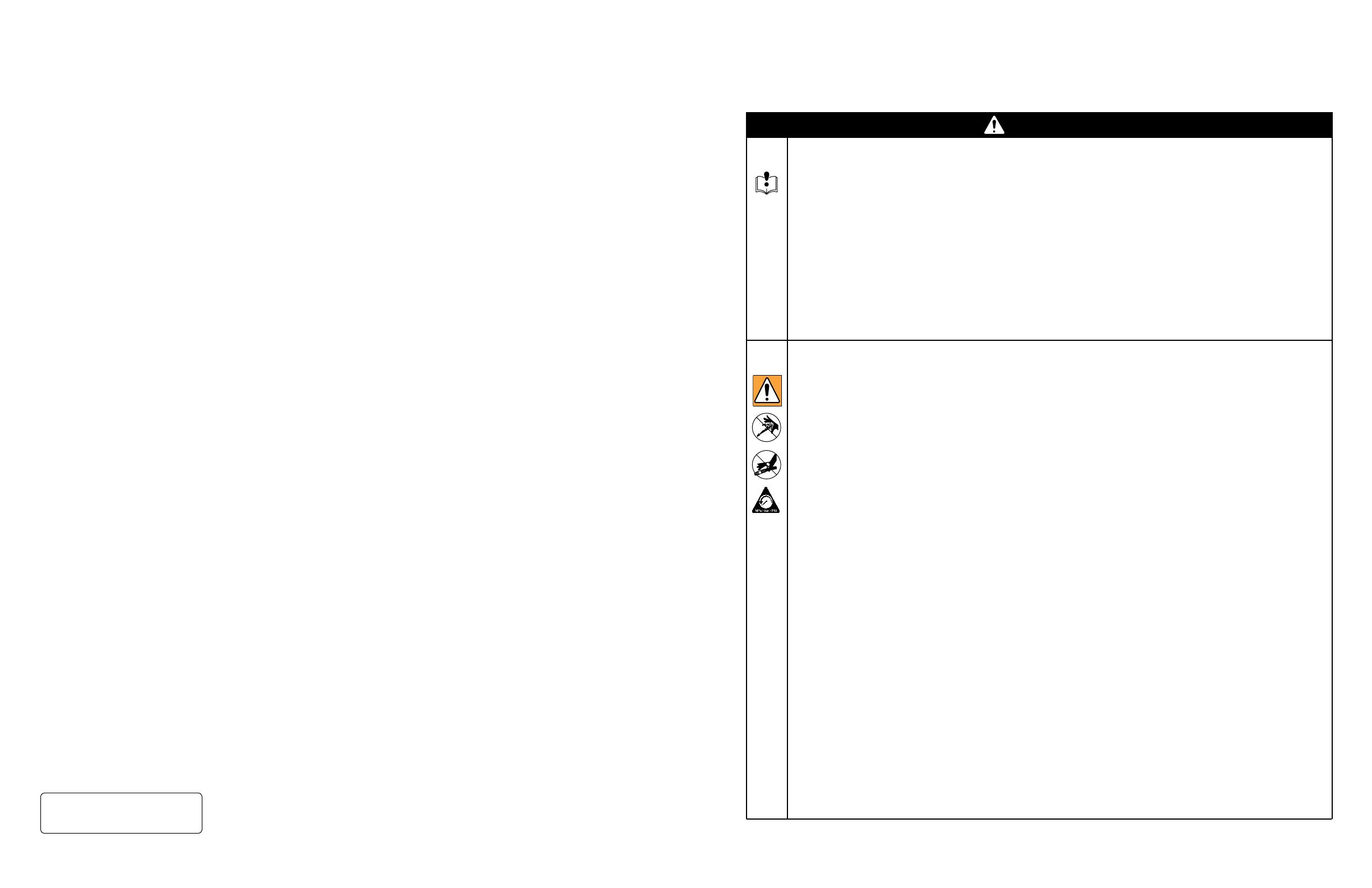
The following warnings are for the setup, use, grounding, maintenance, and repair of this equipment. The
exclamation point symbol alerts you to a general warning and the hazard symbols refer to procedure-spe-
cic risks. When these symbols appear in the body of this manual, refer back to these Warnings. Product-
specic hazard symbols and warnings not covered in this section may appear throughout the body of this
manual where applicable.
IMPORTANT USER INFORMATION
The engine exhaust from this product contains chemicals known to the State of California to cause cancer,
birth defects or other reproductive harm.
This product contains one or more chemicals known to the State of California to cause cancer and birth
defects or other reproductive harm.
The following is required by California State law, Section 4442 of the California Public Resources Code.
Other states may have similar laws. Federal laws apply on federal lands.
• A spark arrester must be added to the mufer of this engine if it is to be used on any forest covered,
brush covered or grass covered unimproved land. The arrester must be maintained in effective working
order by the operator.
• See your engine or equipment dealer for spark arrester mufer options.
SPRAY PRECAUTIONS
Risk of injection or severe cutting injury. If an accident does occur and the spray appears to have pen-
etrated the skin, seek emergency medical care. Do not treat as a simple cut. If you are using cleaning
agents, be prepared to tell a physician exactly what kind.
• Keep clear of nozzle.
• Do not direct discharge stream at persons or pets.
• Only trained operators should use this product. When operating this unit, basic precautions should
always be observed.
• Keep away from the spray. Because of the high pressure and velocity of the spray, uids can penetrate
the skin, causing serious injury.
• Never point the gun at yourself or anyone else. Never put your hand, ngers or body directly over the
spray nozzle. Always keep operating area clear of all persons. Use extreme caution when operating
near children.
Always wear protective goggles when operating the unit to shield the eyes from ying debris and deter-
gents. Other protective equipment such as rubber suits, gloves and respirators are advisable, especially
when using cleaning detergents. Use extreme caution when operating near children.
• Stay alert-watch what you are doing. Do not operate the unit when fatigued or under the inuence of
alcohol or drugs.
• Never squeeze the trigger unless securely braced. The thrust from the water traveling through the
nozzle may be powerful enough to cause the operator to lose balance if unprepared. Do not overreach
or stand on unstable support. Wet surfaces can be slippery, wear protective foot gear and keep good
footing and balance at all times. Never trigger the gun while on a ladder or roof.
• Caution should be used when directing spray toward fragile materials such as glass. Shattering could
result in serious injury.
• Always hold on rmly to the gun/wand assembly when starting and operating the unit. Failure to do so
can cause the wand to fall and whip dangerously. Never operate the gun with the trigger wired in the
open position. To prevent accidental discharge, the trigger gun should be securely locked when not in
use.
CONTENTS
Important ........................................................................ 3
Spray Precautions ......................................................... 3
Fire & Ventilation Precautions ...................................... 4
Carbon Monoxide Hazard ............................................. 4
Detergent Cleaning Precautions .................................. 4
Burn Hazard ................................................................... 4
Miscellaneous Safety Precautions ............................... 5
Adjustment Precautions ............................................... 5
Personal Protective Equipment .................................. 5
Component Identication ............................................ 6
Installation & Preparation instructions ........................ 7
Attire ................................................................................ 7
Setup ............................................................................... 7
Engine Fuel Tank ............................................................. 8
Nozzle Review ................................................................. 8
Nozzle Connection .......................................................... 9
Water Supply ................................................................... 9
Unloader ........................................................................ 10
Thermal Relief Valve ...................................................... 10
Pre-start Inspection Procedures ................................... 10
Operating Instructions ................................................ 11
Priming The Pump ......................................................... 11
Start-up ......................................................................... 12
Cleaning With Detergents .............................................. 13
Shutdown ...................................................................... 13
Storage & Maintenance Instructions ......................... 14
Engine ............................................................................ 14
Pump ............................................................................. 14
Nozzles .......................................................................... 14
Quick Couplers .............................................................. 14
Winterizing ..................................................................... 15
Troubleshooting ........................................................... 16
WARNING
THIS SPARK IGNITION SYSTEM COMPLIES WITH
CANADIAN ICES-002.
CE SYSTÈME D’ALLUMAGE PAR ÈTINCELLE EST
CONFORME À LA NORME NMB-002 DU CANADA.
Pump Service: 2525 Model Pressure Washers ......... 17
For Outlet Valves ........................................................... 17
For Inlet Valves .............................................................. 17
Servicing Plungers Or Internal Bearings ....................... 17
Servicing V-packings ..................................................... 17
Pump Service: 2730 Model Pressure Washers ......... 18
Valves ............................................................................ 18
Pumping Section ........................................................... 18
Servicing Plungers ......................................................... 18
Servicing V-packings ..................................................... 18
Pump Service: 3030 And 3540 Model Pressure
Washers .................................................................... 19
Valves ........................................................................... 19
Pumping Section ........................................................... 19
Servicing Plungers ......................................................... 19
Servicing V-packings ..................................................... 19
Pressure Washer - Parts 262292- Model 2525DD ..... 20
Pump Assembly - Parts - Series A 24E735 (For Use
With Model 2525DD) ..................................................... 22
Pump Assembly - Parts -Series B 24R713 (For Use
With Model 2525DD) ..................................................... 24
Pressure Washer - Parts 262293- Model 2730DD ..... 26
Pump Assembly - Parts 244749 (For Use With Model
2730DD) .................................................................... 28
Pressure Washer - Parts
262294- Model 3030DD ........................................... 30
262295- Model 3540DD ........................................... 30
Pump Assembly - Parts
24E753 (For Use With Model 3030DD) .................... 32
24E750 (For Use With Model 3540DD) .................... 32
Notes ............................................................................ 34
Technical Data ............................................................. 35
Graco Standard Warranty ........................................... 36

4 5
• Do not direct spray on or into electrical installations of any kind! This includes electrical outlets, light
bulbs, fuse boxes, transformers, etc. Severe electrical shock may occur.
• Even after you shut off the unit, there is high pressure water left in the pump, hose and gun until you
release it by triggering the gun. Before removing the spray nozzle or servicing the unit, always shut off
the unit and trigger the gun to release trapped pressure.
FIRE & VENTILATION PRECAUTIONS
• This unit was designed for outdoor use only. Never operate this unit in an enclosed area. Always make
certain there is adequate air (oxygen) for combustion as well as ventilation to prevent the presence of
poisonous carbon monoxide gases. Beware of poorly ventilated areas or exhaust fans which can cause
inadequate combustion or engine overheating.
• Never operate this unit in the presence of ammable vapors or combustible dust, gases or other com-
bustible materials. (A spark may cause an explosion or re.) When servicing this machine, be especial-
ly careful to properly dispose of any ammable materials. Do not spray ammable liquids.
• Do not smoke while lling engine fuel tank
• Never ll the engine fuel tank while the unit is running or hot. Allow the engine to cool two minutes
before refueling.
• Do not refuel indoors or in a poorly ventilated area.
• Always refuel slowly to avoid the possibility of spilled fuel which may cause a risk of re.
• Do not operate the unit if gasoline is spilled. Wipe unit clean and move the unit away from the spill.
Avoid creating any ignition until the gasoline has evaporated.
• Do not store the unit near an open ame or any equipment such as a stove, furnace, water heater, etc.,
which utilizes a pilot light or devices which can create a spark.
CARBON MONOXIDE HAZARD
Exhaust contains poisonous carbon monoxide, which is colorless and odorless. Breathing carbon monox-
ide can cause death.
• Do not operate in an enclosed area.
DETERGENT CLEANING PRECAUTIONS
• Do not use solvents or highly corrosive detergents or acid type cleaners with this pressure washer.
• Know your detergent. Be prepared to tell a physician exactly what you are using in the event of an
emergency. Read the Material Safety Data Sheet (MSDS) provided with your detergent and all deter-
gent labels. Follow all appropriate instructions regarding preparation use, safety and transportation.
Keep all detergents out of the reach of children.
• Do not use this pressure washer to dispense hazardous detergents.
• Do not alter the detergent injection feature in any manner not prescribed in this manual. Use only genu-
ine replacement parts for necessary repairs.
BURN HAZARD
Equipment surfaces and uid that’s heated can become very hot during operation. To avoid severe burns:
• Do not touch hot uid or equipment.
WARNING
MISCELLANEOUS SAFETY PRECAUTIONS
Never allow children or adolescents to operate this unit.
Read and follow all handling, operations, maintenance and safety instructions listed in this manual and the
engine operator’s manual that accompanies this unit, and provide such information to anyone who will be
operating this unit.
In freezing temperatures, the unit must always be warm enough to ensure there is no ice formation in the
pump. Do not start this unit if it has been transported in an open or under heated vehicle without rst al-
lowing the pump to thaw.
When connecting the water inlet to the water supply mains, local regulations of your water company must
be observed. In some areas the unit must not be connected directly to the public drinking water supply.
This is to ensure that there is no feedback of the detergents into the water supply. (Direct connection is
permitted if a back ow preventer is installed.)
Do not allow any part of your body or the high pressure hose to make contact with the mufer. Avoid
dragging the hose over an abrasive surface such as cement. This causes wear and eventual rupturing.
High pressure hoses should be inspected daily for signs of wear. If evidence of failure exists, promptly re-
place all suspect hoses to prevent the possibility of injury from the high pressure spray. If a hose or tting
is leaking , never place your hand directly on the leak.
Do not operate the unit without all protective covers in place.
Never run the unit with the governor disconnected or operate at excessive speeds.
To reduce the risk of injury, maintain a safe distance for persons while operating this unit. Close supervi-
sion is necessary when operating the unit near children.
Do not leave pressurized unit unattended. Shut off the unit and release trapped pressure before leaving.
Do not move the unit by pulling on the hose.
ADJUSTMENT PRECAUTIONS
• Never alter or modify the equipment, be sure any accessory items and system components being used
will withstand the pressure developed. Use only genuine parts for repair of your pressure washer. Fail-
ure to do so can cause hazardous operating conditions and will void warranty.
• Never make adjustments to the machinery while it is connected to the engine without rst removing the
ignition cable from spark plug. Turning the machinery over by hand during adjustment or cleaning might
start the engine and machinery with it, causing serious injury to the operator.
• Know how to stop the pressure washer and bleed pressures quickly. Be thoroughly familiar with con-
trols.
• Before servicing the unit; turn the unit off, relieve the water pressure, and allow the unit to cool down.
Do not make repairs while unit is running. Service in a clean, dry, at area. Block the wheels to prevent
the unit from moving.
• Follow the maintenance instructions specied in this manual.
PERSONAL PROTECTIVE EQUIPMENT
You must wear appropriate protective equipment when operating, servicing, or when in the operating area
of the equipment to help protect you from serious injury, including eye injury, hearing loss, inhalation of
toxic fumes, and burns. This equipment includes but is not limited to:
• Protective eyewear, and hearing protection.
• Respirators, protective clothing, and gloves as recommended by the detergent manufacturer.
WARNING

6 7
Component Identication
Item Description
1. Detergent Strainer
2. Detergent Hose
3. Water Inlet
4. Water Inlet Strainer
5. Water Outlet
6. Decal - Warning/Caution/Operation
7. Oil Sight Glass
8. Pump
9. Adjustable Unloader Knob
10. Decal - Caution: Risk Of Fire
11. Decal - Warning: Risk Of Burns
12. Engine
13. Thermal Relief Valve
14. High Pressure Discharge Hose
15. Gun Assembly
16. Decal - Warning: Risk Of Injection
17. Quick Connect Nozzle
INSTALLATION & PREPARATION
INSTRUCTIONS
Attire
Proper attire is essential to your safety. It is advised to
utilize whatever means necessary to protect eyes, ears,
and skin. Additional safety attire (such as respiratory
mask) may be required when using detergent cleaning
agents with this washer.
Setup
This unit should only be placed on a level surface to en-
sure proper lubrication for the engine and water pump
while operating.
Do not use unit in an area:
• with insufcient ventilation.
• where there is evidence of oil or gas leaks.
• where ammable gas vapors may be present.
Be certain to block the wheels to prevent the unit from
moving while operating.
Do not allow the unit to be exposed to rain, snow or
freezing temperatures. If any part of the unit becomes
frozen, excessive pressure may build up in the unit
which could cause it to burst resulting in possible seri-
ous injury to the operator or bystanders.
Before initial use, ensure the oil cap/dipstick is inserted
into the pump. Because of varying shipping require-
ments, the pump may need to be shipped with an oil
travel plug instead of the dipstick in the pump. If your
pump has been shipped with an oil travel plug, you
will need to remove it and replace the plug with the oil
dipstick provided with the unit.
Once properly installed, check the oil sight glass on the
pump crankcase. Be certain the oil level is in the center
of the sight glass before each use. If the level appears
to be low, add pump oil and ll only to the center of the
oil sight glass. (Refer to the parts listing for the correct
pump oil) do not overll!
8 9
INSTALLATION & PREPARATION
INSTRUCTIONS
Engine Fuel Tank
Review “Fire & Ventilation Precautions” pg. 4, before
fueling.
Locate the Safety Decals on your unit and heed their
warnings.
A minimum of 86 octane fuel is recommended for use
with this unit. Do not mix oil with gasoline.
Purchase fuel in quantities that may be used within 30
days. Use of clean, fresh lead free gasoline is recom-
mended. Leaded gasoline may be used if lead-free is
unavailable. Do not use gasoline containing methanol
or alcohol.
Check the engine oil level before starting the engine.
(See engine manual.)
Fill the fuel tank according to accompanying engine
manual instructions.
Occasional carburetor and choke adjustments will be
necessary for the engine. Refer to the engine manual
supplied with this unit for proper adjustment proce-
dures.
Review the engine manual accompanying this pressure
washer for correct engine start-up and maintenance
procedures.
Nozzle Review
Various nozzles may be quick-connected into the end
of the wand to change the spray pattern or use the
detergent feature. When using Quick Connects (Q.C.),
be certain the connection is securely locked. If not,
the high pressure water may shoot the nozzle from the
wand, causing severe injury or serious damage.
To determine spray fan, refer to the actual number
stamped on the nozzle. The rst two digits indicate the
spray fan in degrees, i.e.; 0=0°, 15=15°, 25=25°, 40 =
40°, 65=detergent/low pressure.
The 0° nozzle (RED): This is a blasting nozzle. It deliv-
ers a very concentrated stream of water. Be cautious
when using the straight narrow stream. It is not recom-
mended for use on painted or wood surfaces, or items
attached with adhesive backings. Uses: Removing
weeds from sidewalk cracks, stubborn stains from con-
crete, masonry, aluminum and steel, caked mud from
equipment, and cleaning lawn mower undersides.
The 15° nozzle (YELLOW): This is a chiseling nozzle.
The spray should be directed at a 45° angle to the
surface and used like a scraper to remove paint, grease
and dirt. Uses: Surface preparation (removing mildew
stains and paint chips).
The 25° nozzle (GREEN): This is a ushing nozzle.
This pattern is best suited for ushing dirt, mud, and
grime. Uses: Wet sweeping leaves from walks, curbs
and driveways, cleaning stable oors, washing swim-
ming pool bottoms, degreasing engines.
The 40° nozzle (WHITE): This is a wash nozzle. This
wide spray pattern disperses the water pressure over a
large area and is recommended for moderate washing.
Uses: Washing down aluminum siding, cleaning win-
dows, washing vehicles, spraying sidewalks, driveways
and patios. (not available for Model 2525)
The 65° nozzle (BLACK): This is a low pressure de-
tergent application nozzle. This broad spray pattern
distributes solution over vast areas under low pressure.
Uses: Detergent application, misting or rinsing.
INSTALLATION & PREPARATION
INSTRUCTIONS
Nozzle Connection
Be certain the trigger gun is locked in the “OFF” posi-
tion.
The nozzle assembly should be disconnected from
the gun/wand assembly at this time by retracting the
locking ring on the quick-connect tting to remove the
nozzle.
Water Supply
Select a water supply hose which is a quality grade of
garden hose measuring at least 3/4” ID and no longer
than 50 feet.
Check the water inlet strainer to ensure it is clean and
free of any obstructions. Periodic cleaning of the water
strainer will help prevent pump problems.
NOTICE
As a strainer becomes obstructed, it restricts proper
ow of water to the pump. This can result in cavita-
tions which will cause premature failure of pump
packings.
1. Using a screw driver, remove the screen from the water
inlet.
2. Clean or replace if necessary.
Connect the hoses.
1. Connect one end of the water supply hose to the water
inlet of the unit.
2. Connect the other end of the hose to your pressurized
water supply.
Note: Do not use a non-pressurized water supply (i.e.
from a pond or well) with this unit.
3. Connect the high pressure discharge hose to the water
outlet of the unit.
4. Securely connect the other end of the hose to the
gun assembly. (A wrench may be required on some
models.)
5. Connect the wand assembly to the gun/hose
assembly.
Follow the incoming water requirements listed below:
1. Water pressure must be a minimum of 25 pounds per
square inch (PSI) and a maximum of 125 PSI. (A typical
outdoor faucet will generally supply this PSI if turned
completely “ON”.)
2. Incoming GPM must be approximately one gallon more
than the outgoing GPM stated on the pressure washer
nameplate. (You can check GPM by timing how long
it takes to ll a 5 gallon container.)
NOTICE
Incoming water temperature must not exceed 125°F
for Model 2525, and 145°F for other models. Exces-
sive pump damage may result if the water tempera-
ture exceeds this acceptable level.
NOTICE
Damage to the equipment could occur. Never allow
the unit to operate without the incoming water line
attached and the water supply completely turned on.

10 11
OPERATING INSTRUCTIONS
Priming the Pump
It is essential to prime the pump on initial start-up and
each time the water supply is disconnected from the
unit after initial use.
1. Lay the high pressure hose out to remove any loops.
Water ow will constrict the hose, creating tight loops
if the hose is not straight.
Note: The nozzle assembly should not be connected
to the gun assembly at this time. See “Nozzle Connec-
tion” pg. 9.
2. With the trigger gun locked in the “OFF” position, turn
the water supply completely on. Pointing the gun in a
safe direction, unlock the trigger gun and squeeze the
trigger.
Low pressure water will begin owing from the hose/
gun assembly. This allows the unit to prime and purge
any air from the system. The unit is primed when water
ow is uninterrupted by air.
3. Once the unit is primed, release the trigger and lock
the gun in the “OFF” position. Securely connect the
nozzle assembly. (See “Nozzle Connection” pg. 9)
NOTICE
Be certain the nozzle is not connected to the unit
while priming the pump. Priming allows mineral de-
posits to be released from the system which would
obstruct or damage the nozzle assembly resulting in
costly repairs.
INSTALLATION & PREPARATION
INSTRUCTIONS
Unloader
The unloader will either be adjustable or factory preset
depending on the model you purchased.
Adjustable
The unloader valve on your machine is equipped with
an adjustment knob to adjust the pressure. Should
less pressure be required, simply turn the adjustment
knob counterclockwise. To set back to maximum, turn
adjustment knob completely clockwise. Do not over-
tighten.
Factory Preset (2525 DD Only)
The unloader valve on your machine is factory preset
and should only be adjusted by a trained representative.
Do not adjust the pressure on your own.
NOTICE
Do not overtighten the unloader. Breakage could
result in immediate loss of water pressure and
costly repairs.
Thermal Relief Valve
To ensure the water temperature does not exceed
acceptable levels, never allow the pressure washer to
operate in the bypass mode (with the unit running and
the trigger gun closed) for more than three minutes.
A “thermal relief valve” has been added to this unit to
protect the pump. It may begin to open and release
water if the water temperature in the pump has ex-
ceeded 140°F. This will allow fresh, cool water to enter
the system.
Pre-Start Inspection Procedures
Before starting the unit, perform the following proce-
dures:
1. Check the oil level in the pump and engine.
2. Inspect the water inlet strainer. Clean or replace if
necessary. See “Water Supply” pg. 9.
3. Check all hose connections to ensure they are securely
tightened. See “Water Supply” pg. 9.
Inspect for system fuel leaks. If a fuel leak is found,
do not start unit. See “Fire & Ventilation Precau-
tions” pg. 4. Be sure that all damaged parts are
replaced and that the mechanical problems are cor-
rected prior to operation of the unit. If you require
service, contact Graco Customer Service.
Inspect high pressure hoses for kinking, cuts and
leaks. If a cut or leak is found, do not use hose.
Replace hose before starting unit. See “Miscel-
laneous Safety Precautions” pg. 5. Be sure that all
damaged parts are replaced and that the mechani-
cal problems are corrected prior to operation of the
unit. If you require service, contact Graco Customer
Service.
12 13
OPERATING INSTRUCTIONS
Start-Up
Refer to the “Safety Precautions” pgs. 3-5 before start-
ing the unit.
Locate the Safety Decals on your unit and heed their
warnings.
Never look directly into the nozzle. High pressure water
creates a risk of severe injury.
1. With the gun locked in the “OFF” position, point the
trigger gun away from yourself or anyone else. Ensure
the water supply is completely turned on.
2. Disengage the safety lock-off on the gun and squeeze
the trigger. Low pressure water will begin owing from
the nozzle.
3. Be certain the trigger gun remains in an open position
while starting the engine. Brace yourself as the gun
will kickback from the high pressure created by the
pump once the engine has started.
4. Steady the unit during engine start-up. (Refer to the
engine manual accompanying this pressure washer for
the correct procedures needed to start the engine.)
5. Once the engine has started, perform the following
procedures with the gun open:
Inspect for system oil leaks and fuel leaks. If a fuel leak
is found, turn unit off immediately. See “Fire & Ventila-
tion Precautions” pg. 4. Be sure that all damaged parts
are replaced and that the mechanical problems are
corrected prior to operation of the unit. If you require
service, contact Graco Customer Service.
Inspect high pressure hoses for kinking, cuts and
leaks. If a cut or leak is found, do not touch hose at
leak. Turn unit off immediately. Replace hose before
restarting the unit. See “Miscellaneous Safety Pre-
cautions” pg. 5. Be sure that all damaged parts are
replaced and that the mechanical problems are cor-
rected prior to operation of the unit. If you require
service, contact Graco Customer Service.
6. Trigger the gun several times. Be certain to lock the
trigger gun in the “OFF” position whenever changing
the quick connect nozzles.
NOTICE
Do not allow unit to operate in bypass mode (with
trigger closed) for more than three minutes without
triggering the gun. Failure to follow this simple rule
can cause premature failure of pump packing seals,
resulting in costly pump repair.
Because your pressure washer delivers a high pressure
spray and a variety of spray patterns, there are many
cleaning jobs that can be done without the use of de-
tergents. If a cleaning agent is required, see “Cleaning
With Detergents” pg. 13 for the correct procedures.
NOTICE
Do not allow spray pattern to remain on a xed area
for an extended period of time. Possible damage
may occur to the area.
OPERATING INSTRUCTIONS
Cleaning with Detergents
Refer to “Detergent Cleaning Precautions” pg. 4 before
working with detergents. Be certain to wear protective
safety attire.
Prepare detergent solution according to label directions.
Never pump acids, alkaline, abrasive uids or solvents
through the unit.
Some units are equipped with adjustable detergent
knobs. Locate the clear vinyl hose which leads to the
pump head.
• If your injector is equipped with an adjustment knob
on the pump head, you may adjust the amount of
detergent desired by turning the knob completely
counterclockwise to set at the maximum siphon rate.
• If your injector is not equipped with an adjustment
knob, the detergent ratio is preset and cannot be
adjusted.
1. Immerse the detergent strainer into the detergent
solution to allow detergent to siphon.
2. With the trigger gun locked in the “OFF” position,
secure quick-connect the detergent spray nozzle
(#6540° BLACK) into the end of the wand.
Note: This injection system is designed to apply deter-
gents under low pressure only. It will not allow deter-
gent solutions to be introduced into the system unless
the nozzle assembly is in the low pressure detergent
mode.
3. To apply solution; unlock the trigger gun and squeeze
the trigger. In a few moments a detergent/water mixture
will exit the low pressure nozzle. Start spraying the
lower portion of the surface being cleaned and move
up, using long overlapping strokes. Applying from the
bottom up helps avoid streaking. Allow to soak briey.
Do not allow detergent solution to dry on the surface.
(Avoid working on hot surfaces or in direct sunlight to
minimize the chances of the detergent drying, which
may result in damaging painted surfaces.) Be certain
to rinse a small section at a time.
4. To rinse; lock the trigger gun in the “OFF” position,
securely quick-connect the desired high pressure
nozzle into the end of the wand. Unlock the trigger gun
and spray. It will take about 30 seconds to purge all
detergent from the line. For best rinsing results, start
at the top and work down.
5. Siphon a gallon of water through the low pressure
detergent injection system after each use. This
prevents the possibility of corrosion or detergent
residue causing mechanical problems during the next
use.
Shutdown
1. Turn engine “OFF” as directed in the engine manual.
2. Turn the water supply “OFF”.
3. Pointing the gun in a safe direction, trigger gun
momentarily to relieve any trapped pressure.
4. Once pressure is relieved, disconnect the nozzle
assembly.
5. Disconnect and drain gun, wand and hoses.
6. Wipe unit clean and store with gun, wand and hoses
in a safe, non-freezing area.

14 15
STORAGE & MAINTENANCE
INSTRUCTIONS
Engine
The engine instructions that accompany your unit detail
specic procedures for maintenance of the engine. Fol-
lowing the engine manufacturer’s recommendations will
extend engine work life.
Pump
The pump oil must be changed after the rst 25 hours
of operation on all units. Once the initial oil change has
been completed, it is recommended the oil be changed
every 3 months or 250 hour intervals. If oil appears
dirty or milky, changes may be required at a greater
frequency. Add pump oil and ll only to the center of
the sight glass (Refer to the parts listing for the correct
pump oil). Do not overll.
Nozzles
Water ow through the spray nozzle will erode the ori-
ce, making it larger, resulting in a pressure loss. Noz-
zles should be replaced whenever pressure is less than
85% of the maximum. The frequency of replacement
will depend upon such variables as mineral content in
the water and number of hours the nozzle is used.
Quick Couplers
There is an o-ring seal inside the female quick coupler.
This o-ring will deteriorate or, if the unit is allowed to
pump without the high pressure hose or nozzle at-
tached, the o-ring may be blown out occasionally.
Simply insert a replacement o-ring to correct the leak.
(Additional o-rings can be purchased from your dealer.)
STORAGE & MAINTENANCE
INSTRUCTIONS
Winterizing
For storage and transportation purposes in subfreezing
ambient temperatures, it will be necessary to winter-
ize this unit. This unit must be protected to the lowest
incurred temperature for the following reasons:
• If any part of the pumping system becomes frozen;
excessive pressure may build up in the unit which
could cause the unit to burst resulting in possible
serious injury to the operator or bystanders.
• The pumping system in this unit may be permanently
damaged if frozen. Freeze damage is not covered by
warranty.
If you must store your unit in an area where the tem-
perature may fall below 32°F, you can protect your unit
by following the procedure outlined below.
NOTICE
Do not store/operate unit in a freezing environment.
Damage to washer could occur.
Gather the following items:
• Two 5 gallon containers.
• One gallon of antifreeze. (Graco® recommends an
environmentally safe antifreeze.)
• Water supply.
• Three foot hose, 1/2-3/4 I.D. with a 3/4 inch male
garden hose tting.
Procedure:
1. To start winterizing, unit must be run and primed
according to the “Start-up Procedures” listed on page
12.
2. After running and priming, shut off the unit and water
supply.
3. Relieve system pressure by pointing the trigger gun in
a safe direction and squeezing the trigger until water
ow ceases to exit the nozzle.
4. Lock the trigger gun in an OFF position and remove
the nozzle.
5. In one 5 gallon container, mix the antifreeze and water
according to manufacturer’s recommendations for the
temperature to which you are winterizing.
Note: Proper winterizing is based on the recommend-
ed manufacturer’s instructions listed on the “Protec-
tion Chart” shown on the back label of most antifreeze
containers.
6. Remove the water supply hose from the unit and
attach the 3 foot hose securely to the inlet connection.
Submerge the other end into the antifreeze solution.
7. Shut off the detergent injector if applicable.
8. Point the wand into the empty container and start the
unit.
9. Trigger the gun until the antifreeze begins to exit the
wand. Release the trigger for 3 seconds, then trigger
the gun for 3 seconds. Continue cycling the gun
several times until all the antifreeze mixture is siphoned
from the container.
10 Stop the unit.
11. Detach the 3 foot hose from the unit and drain any
excess antifreeze back into the 5 gallon container.
12 Disconnect the hose/gun/wand assembly from the unit
and drain any excess antifreeze back into the 5 gallon
container.
13. Store the hose, gun and wand with the unit in a safe,
non-freezing area.
14. Store antifreeze solution for next use or dispose of
according to state EPA laws.
Optional Procedure:
1. Shut the unit and water supply off.
2. Relieve system pressure by pointing the trigger gun in
a safe direction and squeezing the trigger until water
ow ceases to exit the nozzle.
3. Disconnect and drain the hose, gun and wand.
4. Start the unit and allow it to run until all the water exits
the unit. Once the water has stopped owing from the
unit, turn the unit off.
NOTICE
When using this procedure, caution should be used
as ice chips can form from drops of water which
could cause the unit to burst if starting before com-
pletely thawed.
32˚F 0˚C
17
Troubleshooting
Engine will not start. Various engine problems. Refer to the engine manual accom-
panying your unit.
Unit components are frozen. Allow to thaw. If any part of the unit
becomes frozen; excessive pres-
sure may build up in the unit which
could cause the unit to burst result-
ing in possible serious injury to the
operator or bystanders.
No discharge at nozzle when trig-
ger mechanism is squeezed.
Inadequate water supply. Ensure hose is 3/4” (19.05mm) di-
ameter and incoming water supply
is turned on.
Low or uctuating pressure. Kink in water inlet hose. Remove kink.
Kink in high pressure discharge
hose.
Replace hose.
Water inlet screen obstructed. Remove screen, clean or replace.
Pump sucking air. (Prime eliminated) Tighten all water intake connec-
tions. Eliminate leaks in intake line.
Not in high pressure mode. Insert a high pressure nozzle.
Obstructed or worn spray nozzle. Remove, clean or replace.
Damaged or obstructed valve as-
sembly on pump.
Remove, inspect, clean or replace.
Pump packing worn. Replace packings.
Bypass valve not operating correctly. Repair or replace.
Water is leaking from the “Heat
Dump Valve”.
Water temperature is too high. Do not allow the unit to operate in
the bypass mode (with trigger gun
closed) for more than 3 minutes.
Defective valve. Replace.
Oil appears milky or foamy. Water in oil. Change pump oil. Fill to proper
level.
Oil leaking from unit. Do Not Use. Contact Customer Service.
Detergent will not siphon into Low
Pressure Detergent mode.
Detergent strainer is not completely
submerged in detergent solution.
Check, submerge if necessary.
Detergent strainer is obstructed. Inspect, clean or replace.
Detergent hose cut, obstructed. Inspect, clean or replace.
Detergent adjusting knob on pump
turned to closed position. (If appli-
cable.)
Open adjusting knob. Refer to
“Cleaning with Detergents” pg.13.
Not in low pressure mode. Insert 6540° (BLACK) nozzle.
Nozzle assembly is plugged. Clean or replace.
Too many high pressure hose exten-
sions attached to the water outlet.
Use one extension maximum.
Ball and Spring in Venturi stuck. Remove, clean or replace.
Water ows back into detergent
container.
Ball and Spring in Venturi reversed,
missing or corroded.
Remove, clean or replace.
Water ows from the nozzle when
the trigger gun is locked in the
“OFF” position.
Gun is malfunctioning. Repair or replace.
Problem Cause Solution
PUMP SERVICE: 2525 MODEL
PRESSURE WASHERS
Repair kits are available. See the Parts List, page 24.
For the best results, use all parts in kits.
Follow Shutdown Procedure, page 13, to relieve system
pressure.
• Drain and rell pump after 25 hours of operation.
For Outlet Valves
1. Remove hex plug from the manifold using a 14mm
wrench.
2. Examine o-ring located under hex plug. Replace if cut
or distorted.
3. Remove valve assembly from cavity. The assembly
may come apart!
4. Install new valve, o-ring and hex plug. Torque to 14.75
ft-lb (20 Nm)
Note: Re-torque the plug after 5 hours operation.
For Inlet Valves
1. Remove 4 hex bolts from the manifold using a 6mm
hex bit.
2. Carefully separate manifold from crankcase. You may
have to lightly tap the manifold with a soft mallet to
loosen it.
3. Using a screwdriver, press valves out of the manifold
through the 3 holes located on the backside of the
manifold (look for the stainless valve seats through the
holes).
4. Remove the valve.
5. Install new o-ring. Then install new valve assembly.
Reinsert brass plugs.
6. Reinstall manifold to pump. Torque hex bolts to 14.75
ft-lb (20 Nm).
Servicing Plungers or Internal Bearings
1. Damage to the plungers or any internal parts in the
pump housing is considered a catastrophic failure
and is not recommended for service. Replace pump if
necessary.
Servicing V-Packings
1. Remove manifold as described in Valve Replacement
Section.
2. Remove white retaining ring, this may be stuck on the
piston.
3. Remove packing from manifold.
4. Inspect all parts and replace as necessary.
5. Thoroughly clean packing cavities and inspect for
damage.
6. Lightly grease packing cavities. Replace packings in
the following order:
• packing
• retainer ring
NOTICE
Packings must be installed in the proper order and
facing the correct direction. Improperly installed
parts will cause the pump to malfunction.
7. Remove brass retainer located around the piston.
8. Remove the outer and inner o-rings on the brass
retainer.
9. Replace o-rings, reinstall brass retainer around
piston.
10. Reassemble manifold. Torque hex bolt to 14.75 ft-lb
(20 Nm).

18 19
PUMP SERVICE: 2730 MODEL
PRESSURE WASHERS
Repair kits are available. See the Parts List, page 28
(2730B). For the best results, use all parts in kits.
Follow Shutdown Procedure, page 13, to relieve system
pressure.
• Drain and rell pump after 25 hours of operation.
Valves
For a set of six valves, order Valve Assembly Kit
804402.
1. Remove hex plug from the manifold using a 22mm
wrench.
2. Examine o-ring located under hex plug. Replace if cut
or distorted.
3. Remove valve assembly from cavity. The assembly
may come apart!
4. Install new valve, o-ring and hex plug. Torque to 60
ft-lb (81 Nm)
Note: Retorque the plug after 5 hours operation.
Pumping Section
1. Remove capscrews and lock washers from manifold.
2. Carefully separate manifold from the crankcase. You
may have to lightly tap the manifold with a soft mallet
to loosen it.
NOTICE
To avoid damage to plunger or seals, keep manifold
properly aligned with the ceramic plungers when
you remove it.
3. Carefully examine each plunger for any scoring or
cracking. Replace as necessary.
Servicing Plungers
1. Loosen plunger retaining nut ve or six turns using a
13mm wrench. Push plunger toward the crankcase to
separate plunger and retaining screw.
2. Remove nut from plunger and examine and clean
o-ring, backup ring, and copper bearing/gasket
washer.
3. Remove plunger and inger from plunger shaft. Clean
parts as necessary.
4. Inspect plunger shaft for oil leaks from crankcase. If
leaking is obvious, replace oil seals. Otherwise, DO
NOT remove these seals because they cannot be
reused. Oil Seal Kits are available for replacing seals.
5. Lightly grease the inger (and oil seal if it is being
replaced) on plunger shaft. Then install plunger.
6. Lightly grease the retaining screw and outer end of the
plunger. Place washer, o-ring and backup ring around
screw and install nut through plunger. Torque to 11.0
ft-lb (15 Nm).
Note: If replacing packings, see Servicing V-Packings.
7. Lubricate outside of each plunger. Slide the manifold
on the crankcase, being careful not to damage seals.
8. Install capscrews and washers nger tight. Torque
screws to 8.8 ft-lb (12 Nm) following the tightening
pattern in the following gure.
NOTICE
Uneven tightening could cause the manifold to bind
or jam.
Servicing V-Packings
1. Remove manifold as described in Pumping Section.
2. Carefully pull packing retainer from manifold. Examine
o-ring. Replace o-ring if cut or damaged.
3. Remove V-packing and head ring. Pull out retainer ring.
Remove second V-packing and second head ring.
4. Inspect all parts and replace as necessary.
5. Thoroughly clean packing cavities and inspect for
damage.
6. Lightly grease packing cavities. Replace packings in
the following order:
• head ring
• v-packing
• intermediate ring
• head ring
• v-packing
• packing retainer
• o-ring in retainer groove
NOTICE
Packings must be installed in the proper order and
facing the correct direction. Improperly installed
parts will cause the pump to malfunction.
7. Reassemble manifold following procedure described
in Servicing Plungers.
PUMP SERVICE: 3030 AND 3540
MODEL PRESSURE WASHERS
Repair kits are available. See the Parts List, page 32,
34. For the best results, use all parts in kits.
Follow Shutdown Procedure, page 13, to relieve system
pressure.
• Drain and rell pump-after 25 hours of operation.
Valves
For a set of six valves, order Valve Assembly Kit
804402.
1. Remove hex plug from the manifold using a 27mm
wrench.
2. Examine o-ring located under hex plug. Replace if cut
or distorted.
3. Remove valve assembly from cavity. The assembly
may come apart!
4. Install new valve, o-ring and hex plug. Torque to 73
ft-lb (99 Nm).
Note: Retorque the plug after 5 hours operation.
Pumping Section
1. Remove capscrews and lock washers from manifold.
2. Carefully separate manifold from the crankcase. You
may have to lightly tap the manifold with a soft mallet
to loosen it.
NOTICE
To avoid damage to plunger or seals, keep manifold
properly aligned with the ceramic plungers when
you remove it.
3. Carefully examine each plunger for any scoring or
cracking. Replace as necessary.
Servicing Plungers
1. Loosen plunger retaining nut ve or six turns using a
13mm wrench. Push plunger toward the crankcase to
separate plunger and retaining screw.
2. Remove nut from plunger and examine and clean
o-ring, backup ring, and copper bearing/gasket
washer.
3. Remove plunger and inger from plunger shaft. Clean
parts as necessary.
4. Inspect plunger shaft for oil leaks from crankcase. If
leaking is obvious, replace oil seals. Otherwise, DO
NOT remove these seals because they cannot be
reused. Oil Seal Kits are available for replacing seals.
5. Lightly grease the inger (and oil seal if it is being
replaced) on plunger shaft. Then install plunger.
6. Lightly grease the retaining screw and outer end of the
plunger. Place washer, o-ring and backup ring around
screw and install nut through plunger. Torque to 11.0
ft-lb (15 Nm).
Note: If replacing packings, see Servicing V-Packings.
7. Lubricate outside of each plunger. Slide the manifold
on the crankcase, being careful not to damage seals.
8. Install caP screws and washers nger tight. Torque
screws 14.7 ft-lb (20 Nm) following the tightening
pattern in the following gure.
NOTICE
Uneven tightening could cause the manifold to bind
or jam.
Servicing V-Packings
Two packing kits are available: one kit contains pack-
ings only. The other includes packings, rings and retain-
ers.
1. Remove manifold as described in Pumping Section.
2. Carefully pull packing retainer from manifold. Examine
o-ring. Replace o-ring if cut or damaged.
3. Remove V-packing and head ring. Pull out retainer ring.
Remove second V-packing and second head ring.
4. Inspect all parts and replace as necessary.
5. Thoroughly clean packing cavities and inspect for
damage.
6. Lightly grease packing cavities. Replace packings in
the following order:
• head ring
• v-packing
• intermediate ring
• head ring
• v-packing
• packing retainer
• o-ring in retainer groove
NOTICE
Packings must be installed in the proper order and
facing the correct direction. Improperly installed
parts will cause the pump to malfunction.
7. Reassemble manifold following procedure described
in Servicing Plungers.
51
47
83
26
51
47
83
26

20 21
Pressure Washer - Parts
262292- Model 2525DD
Pressure Washer - Parts
262292- Model 2525DD
DESCRIPTION PART # QTY
1 GROMMET 16E489 5
2 NOZZLE, 0° 805535 1
- NOZZLE, 15° 805536 1
- NOZZLE, 40° 805538 1
- NOZZLE, DETERGENT 805634 1
3 DECAL - G-FORCE 2525DD 16E123 1
4 BASEPLATE 16E506 1
5p DECAL - WARNING/CAUTION (E/S/F) N/A 1
6 HANDLE 16E515 1
7 LOCKNUT 111040 10
8 ISOLATOR 16E475 2
9 BOLT 100521 2
10 BOLT 114251 4
11 DECAL- SILVER STICKER N/A 1
12 SPACER 16E512 2
13 WASHER 111841 4
14 WHEEL 16E476 2
DESCRIPTION PART # QTY
15 CAP 16E491 2
16 BOLT 802127 4
17 WASHER 107194 8
18p DECAL - RISK OF FIRE (E/S/F) N/A 1
19p DECAL - RISK OF BURNS (E/S/F) N/A 1
20 ENGINE 16E657 1
21 KEY 197792 1
22 PUMP 24E735 1
23 LOCKWASHER 100214 4
24 BOLT 108842 4
25 O-RING 154594 1
26p DECAL - RISK OF INJECTION (E/S/F) N/A 1
27 LANCE ASSEMBLY 118124 1
28 GUN & WAND - 4000 PSI 246674 1
29 DETERGENT HOSE 117760 1
30 HOSE 16E286 1
31 DECAL - OPERATIONS - (E/S/F) N/A 1
32p DECAL SET, SAFETY 16E947 1
INCLUDES 5, 18, 19, 26, 31
pREPLACEMENT WARNING DECALS AVAILABLE AT NO COST.
22 23
Pump Assembly - Parts - Series A
24E735 (for use with Model 2525DD)
Pump Assembly - Parts
24E735 (for use with Model 2525DD)
DESCRIPTION PART # QTY
KIT, REPAIR, VALVES 24E736 6
INCLUDES 1
KIT, REPAIR, PLUNGER 24E737 3
INCLUDES 2
KIT, REPAIR, OIL SEAL 24E738 3
INCLUDES 3
KIT, REPAIR, UNLOADER 24E739 1
INCLUDES 4
KIT, REPAIR, PACKINGS 24E740 3
INCLUDES 5, 6, 7, 8
KIT, REPAIR, CHEMICAL INJECTOR 24E741 1
INCLUDES 9, 10, 11
THERMAL RELIEF VALVE 117759 1
INCLUDES 12
FILTER, INLET 801112 1
INCLUDES 13

24 25
Pump Assembly - Parts - Series B
24R713 (for use with Model 2525DD)
Pump Assembly - Parts
24R713 (for use with Model 2525DD)
DESCRIPTION PART # QTY
KIT, REPAIR, VALVES 24R715 6
INCLUDES 1
THERMAL RELIEF VALVE 117759 1
INCLUDES 2
FILTER, INLET 801112 1
INCLUDES 3
KIT, REPAIR, PACKINGS 24R718 3
INCLUDES 4
KIT, REPAIR, OIL SEAL 16V292 3
INCLUDES 5
KIT, REPAIR, PISTION 16V302 3
INCLUDES 6
KIT, REPAIR, UNLOADER 24R714 1
INCLUDES 7
KIT, REPAIR, CHEMICAL INJECTOR 24R716 1
INCLUDES 8
26 27
Pressure Washer - Parts
262293- Model 2730DD
Pressure Washer - Parts
262293- Model 2730DD
DESCRIPTION PART# QTY
1 GROMMET 16E489 5
2 NOZZLE, 0° 805535 1
- NOZZLE, 15° 805536 1
- NOZZLE, 25° 805537 1
- NOZZLE, 40° 805538 1
- NOZZLE, DETERGENT 805634 1
3 DECAL - G-FORCE 2730DD 16E124 1
4 BASEPLATE 16E506 1
5p DECAL - WARNING/CAUTION (E/S/F) N/A 1
6 HANDLE 16E515 1
7 LOCKNUT 111040 10
8 ISOLATOR 16E475 2
9 BOLT 100521 2
10 BOLT 114251 4
11 DECAL- SILVER STICKER N/A 1
12 SPACER 16E512 2
13 WASHER 111841 5
14 WHEEL 16E476 2
15 CAP 16E491 2
16 BOLT 100184 4
17 LOCKWASHER 100214 4
18 WASHER 107194 4
19 BOLT 802127 4
20 WASHER 107194 8
DESCRIPTION PART# QTY
21 ENGINE 16E658 1
22p DECAL - RISK OF FIRE (E/S/F) N/A 1
23p DECAL - RISK OF BURNS (E/S/F) N/A 1
24 DETERGENT HOSE 117760 1
25 KEY 197792 1
26 RELIEF VALVE 116461 1
27 PUMP 244749 1
28 QUICK CONNECT 197428 2
29 SWIVEL 16E662 1
30 FILTER 801112 1
31 HOSE ASSEMBLY 244783 1
32 QC SOCKET N/A 1
33 HOSE N/A 1
34 O-RING 156082 2
35p DECAL - RISK OF INJECTION (E/S/F) N/A 1
36 O-RING 154594 1
37 GUN/WAND ASSEMBLY 24E723 1
38 QUICK CONNECT N/A 1
39 WAND N/A 1
40 GRIP N/A 1
41 GUN N/A 1
42 QUICK CONNECT SOCKET N/A 1
43 DECAL - OPERATIONS - (E/S/F) N/A 1
44p DECAL SET, SAFETY 16E947 1
INCLUDES 5, 22, 23, 35, 43
pREPLACEMENT WARNING DECALS AVAILABLE AT NO COST.
28 29
Pump Assembly - Parts
244749 (for use with Model 2730DD)
Pump Assembly - Parts
244749 (for use with Model 2730DD)
DESCRIPTION PART # QTY
KIT, REPAIR, VALVES 804402 6
INCLUDES 24
KIT, REPAIR, OIL SEAL 804033 3
INCLUDES 36
KIT, REPAIR, PLUNGER 804011 3
INCLUDES 37
KIT, REPAIR, PACKINGS 804037 3
INCLUDES 32, 33, 34, 35
KIT, REPAIR, CHEMICAL INJECTOR 24E748 1
INCLUDES 25-31
KIT, REPAIR, UNLOADER 244803 1
INCLUDES 1-23

30 31
Pressure Washer - Parts
262294- Model 3030DD
262295- Model 3540DD
Pressure Washer - Parts
262294- Model 3030DD
262295- Model 3540DD
DESCRIPTION PART # QTY
1 GROMMET 16E489 5
2 NOZZLE (3030DD), 0° 805539 1
- NOZZLE (3030DD), 15° 805540 1
- NOZZLE (3030DD), 25° 805541 1
- NOZZLE (3030DD), 40° 805542 1
- NOZZLE (3540DD/3030DD), DETERGENT 805634 1
- NOZZLE (3540DD), 0° 805543 1
- NOZZLE (3540DD), 15° 805544 1
- NOZZLE (3540DD), 25° 805545 1
- NOZZLE (3540DD), 40° 805546 1
3 DECAL - G-FORCE 3030DD 16E125 1
- DECAL - G-FORCE 3540DD 16E126 1
4 FRAME 16E507 1
5p DECAL - WARNING/CAUTION (E/S/F) N/A 1
6 HANDLE 16E515 1
7 LOCKNUT 111040 6
8 ISOLATOR 16E475 2
9 BOLT 100521 2
10 BOLT 114251 4
11 DECAL- SILVER STICKER N/A 1
12 WHEEL 16E476 2
13 LOCKNUT 119554 2
14 SWIVEL 16E662 1
15 FILTER 801112 1
16 QUICK CONNECT 197428 2
17 RELIEF VALVE 116461 1
18 BOLT 111803 4
DESCRIPTION PART # QTY
19 WASHER 100731 8
20 LOCKNUT 101566 4
21 ENGINE (3030DD 16E659 1
- ENGINE (3540DD) 16E660 1
22p DECAL - RISK OF BURNS (E/S/F) N/A 1
23p DECAL - RISK OF FIRE (E/S/F) N/A 1
24 DETERGENT HOSE 117760 1
25 KEY 801137 1
26 PUMP (3030DD) 24E753 1
- PUMP (3540DD) 24E750 1
27 WASHER 107194 4
28 LOCKWASHER 100133 4
29 BOLT 100004 4
30 HOSE ASSEMBLY 244783 1
31 QC SOCKET N/A 1
32 HOSE N/A 1
33 O-RING 156082 2
34p DECAL - RISK OF INJECTION (E/S/F) N/A 1
35 O-RING 154594 1
36 GUN/WAND ASSEMLBY (3030DD 24E723 1
- GUN/WAND ASSEMLBY (3540DD) 24E724 1
37 QUICK CONNECT N/A 1
38 WAND N/A 1
39 GRIP N/A 1
40 GUN N/A 1
41 QUICK CONNECT SOCKET N/A 1
42 DECAL - OPERATIONS - (E/S/F) N/A 1
43 DECAL SET, SAFETY 16E947 1
INCLUDES 5, 22, 23, 34, 42
pREPLACEMENT WARNING DECALS AVAILABLE AT NO COST.
32 33
Pump Assembly - Parts
24E753 (for use with Model 3030DD)
24E750 (for use with Model 3540DD)
Pump Assembly - Parts
24E753 (for use with Model 3030DD)
24E750 (for use with Model 3540DD)
DESCRIPTION PART # QTY
KIT, REPAIR, VALVES 804402 6
INCLUDES 10
KIT, REPAIR, OIL SEAL 24E744 3
INCLUDES 18
KIT, PLUNGER 24E745 3
INCLUDES 22
KIT, REPAIR, PACKINGS 24E746 3
INCLUDES 11-17
KIT, REPAIR, PLUNGER 24E747 3
INCLUDES 19, 20, 21, 23, 24
KIT, REPAIR, CHEMICAL INJECTOR 24E748 1
INCLUDES 3-9
KIT, REPAIR, UNLOADER (3030) 244804 1
INCLUDES 1, 2
KIT, REPAIR, UNLOADER (3540) 244806 1
INCLUDES 1, 2

34 35
Technical Data
Model 2525 Model 2730 Model 3030 Model 3540
Working Pressure Range 2250-2300 psi 2600-2700 psi 2800-2900 psi 3400-3500 psi
Operating Pressure 2275 psi 2650 PSI 2850 PSI 3450 psi
Maximum Working Pressure 2500 psi 2700 psi 3000 psi 3500 psi
Engine Size 160 cc 200 cc 270 cc 390 cc
Maximum Delivery 2.3 gpm
(8.7 l/mn)
2.4 gpm
(9.08 l/mn)
3.0 gpm
(11.35 l/mn)
4.0 gpm
(15.14 l/mn)
High Pressure Hose 25’ x 3/8”
4000 psi
50’ x 3/8”
4000 psi
50’ x 3/8”
4000 psi
50’ x 3/8”
4000 psi
Chemical Injector Hose 1/4” x 4’ 1/4” x 4’ 1/4” x 4’ 1/4” x 4’
Weight 75 LB (28 lg) 88 LB (32.8 kg) 129 LB (48.2 kg) 142 LB (53 kg)
Dimensions
Length
Width
Height
37” (94 cm)
21” (53 cm)
24.5” (62 cm)
30” (76 cm)
21” (53 cm)
26” (66 cm)
34” (86 cm)
23.5” (59.6 cm)
25.5” (64.7 cm)
34” (86 cm)
23.5” (59.6 cm)
25.5” (64.7 cm)
Pump Inlet Fitting 3/4” ghf 3/4” ghf 3/4” ghf 3/4” ghf
Storage Temperature Range -30° – 125°F
(-34° – 52°C)
-30° – 145°F
(-34° – 62.7°C)
-30° – 145°F
(-34° – 62.7°C)
-30° – 145°F
(-34° – 62.7°C)
Operating Temperature Range 40° – 125°F
(4.4° – 51.6°C)
40° – 125°F
(4.4° – 51.6°C)
40° – 125°F
(4.4° – 51.6°C)
40° – 125°F
(4.4° – 51.6°C)
Sound Pressure 90.4 dB(A) 89.6 dB(A) 93.1 dB(A) 92.2 dB(A)
Sound Power 104.4 dB(A) 103.6 dB(A) 107.2 dB(A) 106.4 dB(A)
Gasoline Tank Capacity 0.5 gal 0.95 gal 1.6 gal 1.7 gal
Maximum Input Pressure 125 psi 125 psi 125 psi 125 psi
Maximum Operating Temperature 125°F
(51.6°C)
145°F
(62.7°C)
145°F
(62.7°C)
145°F
(62.7°C)
Notes

36
Graco Standard Warranty
Graco warrants all equipment referenced in this document which is manufactured by Graco and bearing its name
to be free from defects in material and workmanship on the date of sale to the original purchaser for use. With
the exception of any special, extended, or limited warranty published by Graco, Graco will, for a period of twelve
months from the date of sale, repair or replace any part of the equipment determined by Graco to be defective. This
warranty applies only when the equipment is installed, operated and maintained in accordance with Graco’s written
recommendations.
This warranty does not cover, and Graco shall not be liable for general wear and tear, or any malfunction, damage or
wear caused by faulty installation, misapplication, abrasion, corrosion, inadequate or improper maintenance, neg-
ligence, accident, tampering, or substitution of non-Graco component parts. Nor shall Graco be liable for malfunc-
tion, damage or wear caused by the incompatibility of Graco equipment with structures, accessories, equipment
or materials not supplied by Graco, or the improper design, manufacture, installation, operation or maintenance of
structures, accessories, equipment or materials not supplied by Graco.
This warranty is conditioned upon the prepaid return of the equipment claimed to be defective to an authorized
Graco distributor for verication of the claimed defect. If the claimed defect is veried, Graco will repair or replace
free of charge any defective parts. The equipment will be returned to the original purchaser transportation prepaid.
If inspection of the equipment does not disclose any defect in material or workmanship, repairs will be made at a
reasonable charge, which charges may include the costs of parts, labor, and transportation.
THIS WARRANTY IS EXCLUSIVE, AND IS IN LIEU OF ANY OTHER WARRANTIES, EXPRESS OR IMPLIED, IN-
CLUDING BUT NOT LIMITED TO WARRANTY OF MERCHANTABILITY OR WARRANTY OF FITNESS FOR A PAR-
TICULAR PURPOSE.
Graco’s sole obligation and buyer’s sole remedy for any breach of warranty shall be as set forth above. The buyer
agrees that no other remedy (including, but not limited to, incidental or consequential damages for lost prots, lost
sales, injury to person or property, or any other incidental or consequential loss) shall be available. Any action for
breach of warranty must be brought within two (2) years of the date of sale.
GRACO MAKES NO WARRANTY, AND DISCLAIMS ALL IMPLIED WARRANTIES OF MERCHANTABILITY AND
FITNESS FOR A PARTICULAR PURPOSE, IN CONNECTION WITH ACCESSORIES, EQUIPMENT, MATERIALS OR
COMPONENTS SOLD BUT NOT MANUFACTURED BY GRACO. These items sold, but not manufactured by Graco
(such as electric motors, switches, hose, etc.), are subject to the warranty, if any, of their manufacturer. Graco will
provide purchaser with reasonable assistance in making any claim for breach of these warranties.
In no event will Graco be liable for indirect, incidental, special or consequential damages resulting from Graco sup-
plying equipment hereunder, or the furnishing, performance, or use of any products or other goods sold hereto,
whether due to a breach of contract, breach of warranty, the negligence of Graco, or otherwise.
For Graco Canada Customers
The Parties acknowledge that they have required that the present document, as well as all documents, notices and
legal proceedings entered into, given or instituted pursuant hereto or relating directly or indirectly hereto, be drawn
up in English. Les parties reconnaissent avoir convenu que la rédaction du présente document sera en Anglais,
ainsi que tous documents, avis et procédures judiciaires exécutés, donnés ou intentés, à la suite de ou en rapport,
directement ou indirectement, avec les procédures concernées.
Graco Information
TO PLACE AN ORDER, contact your Graco distributor or call 1-800-690-2894 to identify the nearest distributor.
All written and visual data contained in this document reects the latest product information available at the time of
publication.
Graco reserves the right to make changes at any time without notice.
For patent information, see www.graco.com/patents.
Original instructions. This manual contains English. MM 3A0465
Graco Headquarters: Minneapolis
International Ofces: Belgium, China, Japan, Korea
GRACO INC. AND SUBSIDIARIES P.O. BOX 1441 MINNEAPOLIS, MN 55440-1441 • USA
Copyright 2010, Graco Inc. All Graco manufacturing locations are registered to ISO 9001.
www.graco.com
Revised January 2013
/