Page is loading ...

Use and Care Guide
E L I
Natural Gas(NG)Grill
Model 141.17638900
3=
o Safety
• Assembly
• Use and Care
o Cooking Guide
• Frequently Asked Questions
E
/
/'
Call us first if you have any problem with
this product We can help you with ques-
tions about assembly and grill operation or
if there are damaged or missing parts
when you unpack this unit from the ship-
ping box, Please call before contacting
your local retailer
1-888-317-7642
8am-8pm CST, Monday throuqh E[jday
• NOTE TO ASSEMBLER IINSTALLER:
Leave this guide with the consumer
NOTETO CONSUMER:
Keep this guide for future reference
• RECORDYOURSERIAL#
(see silver CSA label on main body of grill)
• Failure to comply with these instructions could
result in a fire or explosion that could cause
serious bodily injury, death or property damage
o Whether this gritl was assembled by you or
someone else, you must read this entire manual
before using your grill to ensure the gril! is
properly assembled, installed and maintained
• Useyour grill at least 3feet away from any wall
or surface° Use your grill at least 3 feet away
from combustible objects that can melt or catch
fire such as vinyl or wood siding, fences and
overhangs or sources of ignition including pilot
lights on water heaters and live electrical appli-
ances.
• THIS GASAPPLIANCE ISDESIGNED FOR OUT-
DOORUSEONLY.
• Never use your gas grill in a garage, porch,
shed, breezeway or any other enclosed area
• Never obstruct the flow of ventilation air
around your gas grill housing
Never disconnect the gas regulator or any gas
fitting while your grill is lit A lit grill can ignite
leaking gas and cause a fire or explosion which
could result in property damage, personal injury
or death.
Guide # P80174011L - Date:2009/05!21
Sears, Roebuck and Co, Hoffman Estates, IL 60179, USA www.sears.com

Primary Safety Warnings .............. 1-3
Warranty Terms and Conditions ........ 2
Pre-Assembty Instructions ........................ 3
Part Diagrams and Lists .............. 4-8
Assembly Instructions ........................ 9-11
Use & Care Instructions:
• Natura! Gas connection ..... !2
• Lighting Instructions ................. 14
• Troubleshooting .............. 15
• Rotisserie Instruction .......... 16-18
Cleaning and Maintenance ...... 19-20
Cooking Guide ................. A1-A5
Frequently Asked Questions .......... A7-A8
Repair Protection Agreements ............. A9
Kenmore Elite Full Warranty
If this grill fails due to a defect in material or
workmanship within two years fro_,, the date of
purchase, calf 1-800-4-MY-HOME to arrange for
free repair (or' replacement if repair proves impos-
sible)
Limited Warranty on Stainless Steel Burners
Arty stainless steel burner that ever rusts through
will be replaced free of charge After the second
year from the date of purchase you must pay the
labor cost to have it installed,
Limited Warranty on Selected Grill Parts
For three years from the date of purchase, any
stainless or painted steel part will be replaced free
of charge if it rusts through After the second
year from the date of purchase you must pay the
labor cost to have it installed,
All warranty coverage excludes ignitor batteries
and grill part paint toss or rusting (except for rust-
through as specified above), which are either
expendable parts that can wear out from normal
use in less than a year, or are conditions that
can be the result of normal use, accident or
improper maintenance
All warranty coverage is void if this grill is ever
used for commercial or' rental purposes
All warranty coverage applies only if this grill is
used in the United States
This warranty gives you specific legal rights, and
you may have other rights which vary from state
to state
Sears, Roebuck and Co., Hoffman Estates, IL
© Sears Brands, LLC
If you smell gas:
1. Shut off gas to the appliance.
2. Extinguish any open flame.
3, Open lid,
4, If odor continues, keep away from
the appliance and immediately call
your gas supplier or your fire
department,
.................................. ,111,11,!1,!1! ii L[L ±
Natural Gas models must be used with Natural
Gas only LPG models must be used with
Liquid Propane Gas and the regulator' assem*
bly supplied Any attempt to convert the grill
from one fuel type to another is hazardous and
must be performed by a qualified gas techni-
cian only, using a LP Gas Conversion _t
purchased from Sears at 1-8004-MY-HOME
Keep gas regulator hose away from hot grill
surfaces and dripping grease Avoid unneces-
sary twisting of hose Visually inspect hose
prior to each use for cuts, cracks, excessive
wear or other damage. If the hose appears
damaged do not use@the gas grill. Call Sears
at 1-8004-MY-HOME for a certified replace-
ment hose.
California Proposition 65
Combustion byproducts produced when using
this product contain chemicals known to the
State of California to cause cancer, birth
defects, or other reproductive harm
Brass components on the grill, such as hose
fittings, propane cylinder valves (sold sepa-
rately) and burner valve stems, contain lead
which is known to the State of California to
cause cancer, birth defects, or other repro-
ductive harm
Never use charcoal or lighter fluid in this gas
grill. Failure to comply with these instructions
could result in a grease fire or' explosion that
could cause serious bodily injury, death or
property damage
The Grease Draining Tray and Grease Recep-
tacle must be visually inspected before each
grill use RemoveanygreaseandwashGrease
Draining Tray and Grease Receptacle with a
mild soapand warm watersolution Failureto
comply with these instructions co uid result
in a grease fire or explosion that could
cause serious bodily injury, death or prop-
erty damage.

Failure to comply with these instructions may result
in a hazardous situation which, if not avoided, may
result in injury°
Spiders and small insects can spin webs and
nest in the transit and
warehousing gas flow
obstruction around the
Burner FIRE"
can an
unsafe
To
as fo do this
at fall or
wheneve: and if
your grill extended
period of time
1 Remove the screws trom the rear oTeach Main Burner
using a Phillips Head Screwdriver
2 Carefully lift each Burner up and away from the Gas
Valve Orifice
3. Check and clean BurneriVenturi Tubes for insects and
insect nests A clogged tube can lead to afire beneath
the grill
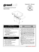
4 Refer to the figure below and perform one of these
3 cleaning methods:
[] METHOD 1: Bend a stiff wire or wire coat hanger
into a small hook as shown and run the hook
through the Burner Tube and inside the Burner
several times to remove debris
TO CLEAN BURNER TUBE,
INSERT HOOK
HERE
Burner Port
Foot
..\
....Burner Tube
[] METHOD 2: Use a bottle brush with a flexible handle
and run the brush through the Burner Tube and
inside the Burner several times to remove any
debris
[] METHOD 3: Use an air hose to force air through
each Burner Tube. The forced air should pass
debris or obstructions through the Burner and out
the Ports
For safe operation ensure the Gas Valve Assembly
Orifice is inside the Burner Tube before using your
grill See figure. If the Orifice is not inside the Burner
Tube, lighting the Burner may cause explosion and!
or fire resulting in serious bodily injury andfor
property damage
Gas Valve Assembly Orifice
Burner Tube
To expedite the assembly process follow these
general guidelines:
[] Tools Required forAssembly :
= protective work gloves
" Phillips Head Screwdriver
[] For your safety, obtain assistance from another person
when assembling this gas grill
[] Use the Hardware and Part Diagrams to ensure all items
are included and free of damage
[]
Do not assemble or operate the grill if it appears dam-
aged, If there are damaged or missing parts when you
unpack the shipping box or you have questions during
the assembly process, call the:
Grill Information Center 1-888-317-7642
8am-8pm CST, Monday throuqh Friday
Grill Installation Codes
The installation must conform with local codes or, in the
absence of local codes, with the National Fuel Gas Code,
ANSI Z223, !/NFPA 54, Storage and Handling of Liquefied
Petroleum Gases, ANSf/NFPA 58,Natural Gas and Propane
Installation Code, CSA B 149 I, Propane Storage and Han-
dfingCode, BI492
1. Do not store or use gasoline or other
flammable liquids or vapors in the vi-
cinity of this or any other appliances.
2. An LP cylinder not connected for use
shall not be stored in the vicinity ofthis
or any other appliance.
When using electrical appliances, basic safety
precautions should always be used,
• This appliance, when installed, must be electri-
cally grounded in accordance with local codes
or, in the absence of local codes, with the
National Electrical Code, ANSI/NFPA 70, or the
Canadian Electrical Code, CSA C22 t
• Keep any electrical supply cord and the fuel
supply hose away from any heated surfaces

PART #
P06001079A
$112G04061
$313G04081
$I 12G04061
$112G03061
$3t3G03051
"Sil GO3O81
$313G03051
PART DESCRIPTION QTY PURPOSE OF PART
Hardware Pack 1 For use in assemblyof Model 141,17638900
Phillips Head Screw 1/4"x318" 6 Install Left and Right Bowl Side Trim Brackets to Bowl Side
Flange Nut 114" 6 Panels
install Rear Bowl Side Trim Bracket to Left and Right Bowl
Phillips Head Screw 114"x3t8" 2
Side Trim Brackets
3
...........Install NG Regulator Bracket to Island Rear Panel
3
Phillips Head Screw 3f16"x3t8"
Flange Nut 3116"
Phillips Head Screw 3116"xlt2" 4
.................. lnstatl Transformer to Cart
Flange Nut 3f16" 4
;! ii
Phillips Head Screw Phillips Head Screw Phillips Head Screw
1/4" x 3!8" 3116" x 112" 3116" x 3/8"
Qty 8 Qty. 4 Qty 3
Part # $112G0406I Part # $tt2G0308t Part # S112G03061
Flange Nut 114"
Qty 6
Part # S313G04081
Flange Nut 3/16"
Qty, 7
Part # S313G03051
* One BatteryfAA included in the Hardware Pack

KEY DESCRIPTION PART# • QTY
1 Lid Assembly ...................................................................... P001473034 1 ..........
2 Temperature Gauge ............. P00601287c 1
3 .Temperature Gauge Sea! P00614027c 1
4 Name Plate P004 I0039C i
I' 5 Protective Pad ............ P055t80021 4
....i ............. ,............................
• 6 Lid Handle P00205106R 1
7 Cooking Rack')Secondary ........................................... ' P01507020G............ 1
8 Cooking Grid 13" P01604013B 1
9 Cooking Gr'id,,,,6:5" P01604031B 1
............................. i ...........................
9a Cooking Grid/Infrared Burner P01615030F 1
.................... z .................... ,, ,
10 Heat Diffuser P017080364 3
11 Heat Diffuser Bracket, Front P033280154 3
12 Heat Diffuser Bracket, Rear P033280174 3
13 Burner P020080324 3
..................... i ..................................
I4 Bowl Assembly P0071366B4 1
15 Burner Bracket P0:_20'34244 ........ 1 ........
16 Grease Draining Plate P069020184 2
17 Electric Wire, 5-contact P02627006A 1
18 Gas Collector Box with Electrode P02609010B 3 .......
19 Electric Wire Set P02615163A 3
20 Lighting Stick Assembly P05507008A 1
21 Gas Valve/Manifold Assem,bl _............................... Y0060646 1
22 Electric,,,,Ignitor,5-port ...................................................... P02502298€ ............ !
23 Electric ignitor Protector P055450027 1
24 Control Panel UpPer......................................................... P0291519FI 1 __
25 Control Panel P0291520FI 1
26 Control Panel Heat Shield P06919001B 1
......................... .................................. ,,,,,_,...........
27 Control Knob Seat P03413023J 5
28 Control Knob Spring P05504021A
29 Control Knob/Main Burner P03426393J
30 Control Knob P03426403J
31 Infrared Burner Thermoc0uP,!e Biacket ......... P033430164
32 Grease Tr,ayHeat Shield, Upper P069030564
33 Rotisserie Burner Wind Shield P069060464
34 Rotisserie Burnei AsSembly ................... P02007'0704
35a ....L!..gh.t..,!.2V,10W ................................. '...................................................i....... P05383002B ..............
35b Light Cover Set P05383003B
35c Light Wire Set P05352005B
36 Rotisserie Burner Electrode P02614025A
37 Rotisserie Burner Orifice
5
3
2
1
1
1
1
2
1
1
1
P06534009A 1
38 Rotisserie Burner Thermoc;'u'pie ........................... ..... P05305051A
39 Rotisserie Burner Thermocouple Bracket P03328047C
.... 40 Bowl Pa.neLReartupper ...................... P069060214
4! ;Rotisserie Burner Extension Tube P03717050B
42 Burner Heat Shield P069060454
43 Infrared Burner Assembly P020050114
1
1
1
I
1
1
6

KEY
44 iinfraredBurner_e_oco,uple...................... PO5305050A..............
.......................... i .............
45 ilnfrared Burner Electrode P02618008B
..... 46 Grease Tray ....................... ......... , ......P02706255B
47 Grease Tray Handle - P00213031M
...... 48 ,Sw,itch ,for Light Assembly ...................... '.......,.........."! ........ P05360002B
49 Bowl Side Trim Bracket, Left P07901026A
..................... t ............................. t
..... 50 Bowl Side Trim Bracket, Right .............. P07901027A
51 Bowl Side Trim Bracket, Rear P07901028A
52 Transformer P05374003B
53 NG Regulator ................. P03614003B
54 _NG Regulator Bracket P033040544
55 Bowl Support Bracket, Left P01301006K
56 Bowl Support Bracket, Righ!......... P01302006K
Rotisserie Assembly
Hardware Pack
Use and Care Guide
DESCRIPTION PART# QTY
1
1
1
1
1
1
1
1
1
1
!
1
1
Y0250169 I
P06001079A 1
P80174011L 1
One BatterylAA Packed with the Use and Care Guide
To purchase Liquid Propane Gas Conversion
Parts call Sears at 1-800-4-MY-HONIE ®
Liquid Propane Gas conver-
sion kit Part #Y0440039
Your grill can be converted to liquid
propane gas with this conversion kit by a
t
qualified gas technician only tn order to ijl lconvert this grill the technician will need L_ lJ _ _'_ _'l
.J
this conversion kit,
For the repair or replacement parts you need:
Call anytime 1-8004-MY-HOME® (1-8oo-469_e63)
To obtain the correct replacement parts for your gas grill, please refer to the part numbers in this parts list The
following information is required to ensure you receive the correct pads:
1. Model and Serial Number (see CSA label on grill)
2. Part Number
3 Part Description
4 Quantity of parts needed
Important: Use only Kenmore replacement parts The use of any part that is not a Kenmore replacement part
can be dangerous and will also void your product warranty Keep this use and care guide for convenient referral
and for part replacement.
7

./
/
0
%
7
8
9
5
#
,.b
_jJ j/
1o
KEY DESCRIPTION PART# Q'rY
1 Rot Collar P05508200L 1
2 Rot. Thumbscrew 1t4"x112" $196G04084 3
4. Rot Spit P05508175F I
5 Rot HoJding Fork P05508090F 2
6 Rot Motor Bracket P05508 !74F t
7 Rot. MotortAC P07101010A 1
8 Rot,, Screw#10-24x3t4"UNC S112G10124 2
9 Rot Washer 3116" S411G03084 2
10 Rot. Nut #10-24 $362G10124 2
Rot, Thumbscrew Rot. Screw#10-24x314" Rot Washer 3f16" Rot Nut#10-24
1/4"x112" UNC Qty, 2 Qty. 2
Qty. 3 Qty, 2 Part # $411G03084 Part # $362G10124
Part # $196G04084 Part # $112G10124
Grill Information Center IfyouhavequestionsaboutassembJyorgrilloperation,oriftherearedamagedormissing
partswhen you unpackthisunitfromtheshippingbox,callus 8:00am -8pm CST, Monday throughFridayat:I-
888-317-7642

install Bowl Side Trim Bracket
[] Install Left Bowl Side Trim Bracket to Left Bowl Panel using 3 Phillips
Head Screws t/4"x3/8" and tighten using 3 Flange Nuts 1f4" as shown,
repeat for the Right Bowl Side Trim Bracket
[] Install Rear Bowl Side Trim Bracket to Left & Right Bowl Side Trim Panels
and tighten using 2 Phillips Head Screws 1t4"x3t8"
Phitiips Head Screw
t/4" x 3!8"
Qty 8
Pad # $112G04061
Flange Nut 114"
Qty 6
Part # $313G04081
Install Grill Head
[] With the assistance of another person, place the Grill Head into the cutout
of your grill island as shown in the Figure
NOTE: This grill head is designed to fit into an island of your own design
The island shown is for illustration purposes only and is not included with
the purchase of this grill head Be sure your island meets the construction
guidelines and clearances as indicated on page 13, Figure 1
Install 12' Natural Gas Hose (not included in this unit)
[] Connect NG Gas Fitting with Hose to Gas Manifold, Install the NG
Regulator Bracket to Island Rear Panel using 3 Phillips Head Screws
3/16" x 3/8" and tighten using 3 Flange Nuts 3/16" as shown
[] Connect the Swivel nut of the 12' Natural Gas Hose (not included
in this unit) to the NG Gas Regulator
Phillips Head Screw
3116" x 3!8"
aty 3
Part # $tt2G03061
Flange Nut 3116"
Qty 3
Part # $313G03051
Gas Manifold ._.... _. :._._'/
Vertical Fitting__ I i
9

Install Transformer
[] Instati Transformer-Plug into Transformer-Socket and tighten securely,
(See Fig 1)
[] lnstat! Transformer to the Rear Cart Panel by using 4 Phillips Head
Screws 3t16"x1/2" and tighten using 4 Ftange Nuts 3116", (See Fig 2)
(You need to make 4 holes on your Rear Cart Panel first)
Pull the Transformer Cord out through the gap between the Rear Cart
Panel and the floor,
[] Plug Transformer Cord into a properly grounded outlet
Note: In case of light bulb failure replace with 12 volt 10W bulb only to avoid
damaging the electrical transformer
Phillips Head Screw
3It6'_ x tt2"
Qty, 4
Part # $112G03081
Fiange Nut 3116"
Qty_ 4
Part # $313G03051
Wire --,,
Transformer-socket ..... '"_t._!
Transformer-plug ---,
Fig
Install ignitor Battery
[] Unscrew Ignitor Cap from Control Panel
[] Place supplied AA battery into the Ignitor Slot with positive pole
facing you,
[] Position the Cap and Spring over the AA battery and tighten onto
Control Panel,
AA Batter
Ignitor
Spring
Ignitor Slot
10

[]
[]
[]
[]
Main Burner Electrode Check
With the assistance of another person,
perform this Electrode Check before
proceeding.
This test wilt ensure that the Spark Electrode Tips
are propedy positioned so your grill lights easily
and properly.
Be sure a!l Control Knobs are set to "OFF" and
open the Grill Lid.
Have your assistant stand behind to the right of
the grill and look toward the front of the grill bowl.
Never put your face inside the Grill Head
Push and turn Burner Control Knob to _. and
you wilt hear a "clicking" sound as the burner
is being ignited Your assistant should see a blue
spark within each Gas Collector Box. If a spark
is present the Electrode Tips are properly po-
sitioned
if no spark is seen, the Spark Gap needs to be
adjusted as follows:
o tf the gap between the Spark Electrode Tip
and Receiver is more than 3!t6" use an
adjustable wrench to gently squeeze the
Gas Collector Box to narrow gap..
= Recheck the Electrode again, if no "clicking"
sound is heard:
AA Battery may be installed backwards
Electric wires may be loose Remove the AA
Battery and inspect the Ignitor Junction Box
found behind the Control Panel and reconnect
any loose wires
Infrared Burner and Rotisserie Burner
Electrode Check
[] Push and turn Infrared Burner Control Knob &
Rotisserie Burner Control Knob to,_.. Look for
spark between electrode tip and spark receiver
tip
[] If you don't see a spark from infrared Burner Elec-
trode or Rotisserie Burner Electrode, adjust gap
between electrode tip and spark receiver tip to 31
16 inch
Install Cooking Components
[] Place the Heat Diffusers above the Burners
The Heat Diffusers can only be placed corr_tty in
one direction, with the underside peg towards the
back ledge.
[] Place the Cooking Grids on the ledge above the
Heat Diffusers
[] Place the Secondary Cooking Rack into the slots
on Grill Bowl Side Panels
Secondary Cooking Rack
Cooking Grids ..................
Heat
31161'_Spark Gap Gas Collecto!
ilill.........lit21)!!illilll
t,\............... tJ ........... j!
tp Spark ElectrodeTip
ark Receiver
Failure to read and follow the Use and Care
Instructions could result inafire orexplosion that
could causeserious bodily injury, death or prop-
erty damage,
When you have finished assembling your grill
be sure that all screws are tightened for safe
operation of your grill,
11

Natural Gas Model only:
Connecting Natural Gas To Your Grill
[] Connect the Swivel nut of the I2' Natural Gas Hose
to the vertical fitting of NG Regulator as shown in
Fig_ 1 Connect the other hose end (male plug) to
the gas supply line from house.. Also, read and foiow
all natural gas safety instructions below.
Natural Gas Safety Instructions
[]
Your natural gas grill is designed to operate on natural
gas only, at a pressure of4" water column (WC) with
natural gas regulator The gas pressure Regulator sup*
plied with this appfance must be used This Regulatoris
set for an outlet pressure of 4" WC
[]
Instal a ShutoffValve at the gas supply source outdoors
at a point after the gas pipe exits the outside wall and
before the quick-disconnect hose..Or install itat the point
before the gas line piping enters the ground. See Fig., 2
[] Pipe sealing compound or pipe thread tape resistant to
the action of natural gas must be used on all mate pipe
thread connections.
[]
Disconnect your gas grill from fuel source when the gas
supply is being tested at high pressures This gas grill
and its individual shutoff valve must be disconnected
from the gas supply pipe system during any pressure
testing of that system at pressure in excess of 1/2 psi
(35kpa)
[] Turn offyour gas grillwhen the gas supply is being tested
at low pressures The grill must be isolated from the gas
supply pipe system by closing its individual manual
shutoff valve during any pressure testing of the gas
supply pipe system at pressures equal to or less than t!
2 psi (35kpa).
Fig. 2
Inside Wall
Gas/Supply
Fig. 1
_,-J_!>) 12ft NG Hose _
_.m, L.,.JI,i _*_/"
l_ _ (not included with grill) <_:_"
i-, _,tI_;_ .... _G__
• • • _-_/ ,!IFJ -'-
Vertical filrng ..... ":_i_" ;>/_//
Swivel nut _-ii_,)
Check all connections for NG Leaks
Never test for' leaks with a lame Prior to first use and
at the beginning of each season, you must check for gas
leaks Follow these three steps:
[] Make a soap solution by mixing one part liquid
detergent and one part water
[] Turn the grill Control Knobs to the full OFF position,
then turn the gas ON at source
[]
Apply the soap solution to al gas connections indi-
cated by the arrows. See Fig. 3 if bubbles appear
in the soap solution the connections are not properly
seated. Check each fitting and tighten or repair as
necessary
Fig, 3 / ........
/
/,
_i_o Grill
Outside Wall
Shut Off
Locking
Shut Off
--- Quick
Male Fitting Disconnect
12
if you have a gas leak that cannot be repaired by
tightening, turn off the gas at the source, disconne_
fuel line from your grill and call 1-800-.4-MY-HOME
or your gas supplier for repair assistance
Never disconnect the gas regulator or any gas
filing while your gdl is lit. A lit grill can ignite
leaking gas and cause a fire or explosion which
could result in property damage, personal injury
or death

CORRECT GAS GRILL USE
E3 The regulator and hose assembly must be inspected
before each use of the grill tf there is excessive
abrasion or wear or if the hose is cut, it must be
replaced prior to using the gd]l again
[] Any attempt to convert the grill from one fuel type to
another is extremely hazardous and must be per-
formed by a qualified gas technician only. using a LP
Conversion Kit purchased from Sears.
[] Never light your gas grill with the lid closed or before
checking to ensure the burner tubes are fully seated
over the gas valve oril;ces
[] Never allow children to operate your grill Do not allow
children or pets to play near your gri]l
[] Use of alcohol, prescription or non-prescription drugs
can impair your ability to properly assemble and safely
operate your grill
[] Keep fire extinguisher readily accessible In the event
of a oi!!grease fire, do not attempt to extinguish with
water Use type B extinguisher or smother with dirt,
sand or baking soda
[] In the event of rain, cover the grill and turn off the
burner and gas supply.
[] Use your grill on a level, stable surface in an area
clear of combustible materials..
[] Do not leave grill unattended when in use
[] Do not move the appliance when in use
[] Allow the grill to cool before moving or storing
[] Do not use your grill as a heater
[] This grill is not intended to be installed in or on
recreational vehicles andtor boats.
[] The grill is not intended for commercial use.
[] Never use charcoal in this gas grill.
If using a LP converted grill, your island must include
air vents as noted below:
NOTE: Upper & lower air vents (20 sq in. minimum
each) MUST BE PROVIDED on both sides of built-
in construction The height from upper air vent to top
surface of island is 5", and the height from lower air
vent to bottom island is 5", see Fig I Please ask
a Sears Associate for full details or call the Grill
Information Center at 1-888-317-7642
Your island construction must conform to these mini-
mum clearance requirements The Side* and Rear* di-
mensions are minimum clearances required from
combustible objects that can melt or catch fire such as
vinyl or wood siding, fences and overhangs or sources
of ignition including pilot lights on water heaters and
live electrical appliances The Height* refers to the rec-
ommended height of island from the ground to counter
Model'' He'ight'l"'W_dthI Depth 1Side* Rear" Height*
Ii76389001i02'i="laS'l'q=S-"a"l'"::1=4,, 13o-i:4"1
/
Height*
Rear"
Construction
6" minimum
clearance from
cutout (for lid)
!
Depth
/
Height
Width
Fig I
Vents
Air Vents
i,j_
Your island must be
constructed of a non-I
combustible material
such as stone, stucco,
brick or tile
t3

Grill Lighting Instructions
1 Before each use, check all hoses for cracks, nicks, cuts,
burns or abrasions, tf a hose is damaged in any way, do not
use your gdll before replacing the hose with an authorized
part from the Parts List Also make sure all gas supply
connections are securely tightened
2 Familiarize yourself with the safety and Use and Care
instructions in this guide. Do not smoke while lighting grill
or checking gas supply connections.
3 Be sure the Natural Gas Line is attached to the gas source
(or if using a professionally converted LP grill, be sure the
LP Gas tank is filled )
4 Open the Grill Lid
Failure to replace a faulty hose, secure gas supply
connections or to open the Lid before proceeding to
the Lighting Procedures could result in a fire or
explosion that could cause serious bodily injury,
death, or property damage.
Burner Control Knobs on Control Panel
,@o @i
Main Burner
,\
\
Rotisserie Infrared
Burner Burner
Rotisserie Burner Lighting Instructions
1Follow steps 1 through 5 of the Grill Lighting Instructions
2 Push and turn Control Knob to ÷ and hold knob in.
3 Keep pressing while you turn knob to HI and hold in 5 _10
seconds before releasing,
4.Ifignition does not occur in 5 seconds, turn gas off at source
and turn Control Knobs OFF Wait at least 5 minutes for gas
to clear, then retry., if your- grill still fails to light turn the
Control Knob(s) and gas source OFF Wait 5 minutes for
gas to clear and then conduct a leak test as explained in
the LP Gas Tank #]stallation of this guide if no leaks are
detected, repeat the lighting procedure
5 After Burner is lit, turn the tank valve SLOWLY one more
1/4 of a turn
5 Set Control Knobs to OFF Open Natural Gas valve at
source if using an LP grill open LP Gas tank valve.
®
....%7;:--.
i .....i j)',)
t
6 Push and turn Right Main Burner Control Knob to _, and
hold in.. You will hear a clicking sound from the elec-
trodes of all burners
Note: Only the burner you are turning on will ignite Once
the burner is lit, turn the knob back to Hi
O
/"__/_ -''¸_¸,¸, ,
7 Ifignitiondoes not occur in 5 seconds, turn gas off at source
and turn Control Knobs OFF. Wait at least 5 minutes for gas
to clear, then retry Ifyour grit] stillfails to light, turn the burner
Control Knob(s) and gas source OFF Wait 5 minutes for gas
to clear and then conduct a leak test of ALL gas connections
and gas sources as explained in the LP Gas Tank Installa-
tion of this guide If no leaks are detected, repeat the lighting
procedure.
8 After one Burner is lit, turn the NG valve (or LP tank valve)
SLOWLY one more 1/4 of a turn
9 Turn each other burner knob to _ to light, then back to Ht.
Note: When lighting all three main burners, start with the
burner' furthest from fuel source location, then light remain-
ing burners in sequence moving toward fuel source,
IMPORTANT: Do not use the Rotisserie Burner and Main
Burners at the same time Rotisserie burner isfor Rotisserie
Cooking only
MAIN BURNER ROTISSERIE
KNOB: ,BURNER KNOB:
INFRARED BURNER
KNOB:
Infrared Burner Lighting Instructions
1 Follow steps 1 through 5 of the Grill Lighting Instructions
2 Push and turn Control Knob to ÷ and hold knob in
3. Keep pressing while you turn knob to Hi and hold in
5 - 10 seconds before releasing
4 If ignition does not occur in 5 seconds, turn gas off at
source and turn Control Knobs OFF. Wait at least 5
minutes for gas to clear, then retry., if your grilt stiIIfails to
light turn the Control Knob(s) and gas source OFF Wait
5 minutes for gas to clear and then conduct a leak test as
explained in the NG Installation of lhis guide If no leaks
are detected, repeat the lighting procedure.
5 After Burner is Iit, turn the NG valve (or LP tank valve)
SLOWLY one more 1/4 of a turn
14

Manually Lighting Your Grill By Paper Match
To light your gas grill by match, insert a match into the Lighting
Stick and follow steps 1 through 5 of the Grill Lighting
Instructions. Then, tight the match and place Lighting Stick
through the Cooking Gdd on the grill as shown below Turn
the nearest Control Knob to the Ht setting to release gas The
Burner should fight immediately
Match !
k._F(
Lighting
Stick ...........
Never lean over the grill cooking area while lighting
your gas grill Keep your face and body a safe distance
(at least 18 inches) from the front of grill when lighting
your grill by match.
i
Should a FLASHBACK fire occur in or around the i
Burner Tubes, follow the instructions below Failure _
to comply _th these instructions could result in a
fire or explosion that could cause serious bodily
injury, death, or property damage
• Shut off gas supply to the gas grill
• Turn the Control Knobs to OFF position,
• Open the Grill Lid,,
° Put out any flame with a Class B fire
extinguisher.,
, Once the grill has cooled down, clean
the Burner Tubes and Burners according
to the cleaning instructions in this Use
and Care Guide.
If ignition does not occur in 5 seconds, turn the Control
Knob(s) and gas source OFF and conduct a leak test
as explained in the Use and Care section of this guide
if no leaks are detected, repeat the lighting procedure.
Troubleshooting
tf the grill fails to light :
1 Turn gas off at source and turn Control Knobs to OFF Wait
at least 5 minutes for gas to clear, then retry
2 if your grill still fails to light, check gas supply and
connections
3 Repeat lighting procedure If your grill sti!l fails to operate,
turn the gas off at source, turn the Control Knobs to OFF,
then check the following:
[] Misalignment of Burner Tubes over Orifices
Correction: Reposition Burner Tubes over OriSces
[] Obstruction in gas line
Correction: Remove fuel line from grill. Do not smoke! Open
gas supply for one second to clear any obstruction from fuel
line. Close off gas supply at source and reconnect fuel line
to gnll
[] Plugged Orifice
Correction', Remove Burners from grilI by removing the
screw from the rear of each Burner using PhiIlips Head
Screwdriver CarefuUy lift each Burner up and away from gas
valve Orifice. Remove the Orifice from gas valve and gently
clear any obstruction with a fine wire Then reinstall all
Orifices, Burners, screws and cooking components
[] Ifan obstruction is suspected in Gas Valves or Manifold, call
the Grilf Information Center 1-888-317-7642 8am to 8pm
CST, Monday through Friday
[] Obstruction in Burner Tubes
Correction: Foflow the Burner Tube cleaning procedure on
page 20 of this Use and Care Guide
[] Misatignment of Ignitor on Burner
Correction: Check for proper position of the Electrode Tip
as shown in steps 6 & 7 on page 11. The gap between the
Spark Electrode Tip and Spark Receiver should be
approximately 3116". Adjust if necessary With the gas
supplyclosed, turn anyMain BurnerControl Knob to _' then
push in and watch for the presence of a spark at the
Electrode.
[] Disconnected Electric Wires
Correction: Inspect the Ignitor Junction Box found behind the
Control Panel.. Connect loose Electric wires to Junction Box
and try to light the grill
[] WeakAA battery
Correction: Unscrew the Ignitor Cap and replace the bat-
tery.
[] If the grill still does not light and you have professionally
converted your grill for LP use, you may need to purge
air from the gas fine or reset the regulator excess gas
flow device Note: This procedure should be done every
time a new LP Gas tank is connected to your grill
To purge air from your gas line and/or reset
the regulator excess gas flow device:
[] Turn Control Knobs to the OFF position
[] Turn off the gas at the tank valve
[] For Natural Gas disconnect regulator from
12 ft Natural Gas Hose.
[] Let unit stand 5 minutes to allow air to purge
[] For Natural Gas reconnect regulator to 12 ft
Natural Gas Hose
[] For Natural Gas open Shut Off valve
[] Open the Grill Lid
[] Push and turn the Riqht Main Burner Control Knob
to _' and you will hear a clicking sound as the
burner is being ignited
[] Once the burner is lit, turn the knob back to H1
15

CORRECT ROTISSERIE USE
Read all instructions before initialuse
IMPORTANT: When using electrical appliances, basic safety
precautions should always be used
The Rotisserie Motor is set for 120V, 60Hz AC current
The Rotisserie is for outdoor use only
Do not let children operate or play near your grill or Rotis-
serie,
Connecting Rotisserie
Always attach the assembled Rotisserie to your grill first
and then plug the Cord into a properly grounded outlet
Operating Rotisserie
Do not operate the Rotisserie if the cord or plug becomes
damaged, or if the Rotisserie malfunctions or has been
damaged in any manner
The use of accessory attachments is not recommeded by
the manufacturer- and may cause injuries. Only use this
Rotisserie for its intended use
Do not immerse Etectdcal Cord, Plug or Motor in water or
expose to rain, as this may result in an electdcai shock,
Discon nect Rotisserie
Be careful as all surfaces witt be hot, both gdll and Rotis-
serie paris. Use protective mitts to handle the Rotisserie
Unplug the Rotissede from electrical outlet when not in use
and before cteaning Aliow to cool before adding or remov-
ing parts
When Roitsserie cooking place a Cooking Pan under the
food to be cooked as this wilf capture the drippings and
keep your grill clean of excess grease which could cause
a fire,
CAUTION: Handle with care when moving a Cooking Pan
with hot oils
Should a grease fire occur, turnthe burners and gas off and
leave the grill lid Closed until the fire is out
Store the Rotisserie indoors
When Rotisserie isnot in use, store it indoors in a dry place,
', This appliance, when installed, must be electri-
cally grounded in accordance with local codes
or', in the absence of local codes, with the
National Electrical Code, ANSI/NFPA 70, or the
Canadian Electrical Code, CSA C22 1
• Keep any electrical supply cord and the fuel
supply hose away from any heated surfaces,
To protect against electrical shock, do not immerse
electrical cord, plugs or motor in water or expose to
rain Protect electrical elements from burners, hot
grill surfaces and grease
To protect against shock hazard risk, connect
only to properly Grounded Outlet
ELECTRICAL EQUIPMENT USE
To protect against electric shock, do not immerse
cord or plugs in water or other liquid
2 Unplug from the outlet when not in use and before
cleaning Allow to cool before putting on or taking off
parts,
3 Do not operate any outdoor cooking gas appliance
with a damaged cord, plug, or after the appliance
malfunctions or has been damaged in any manner
Call 1-800-4-MY-HOM E®for repair
4
5,
Do not let the cord hang over the edge of a table
or touch hot surfaces
Do not use an outdoor cooking gas appliance for
purposes other than intended
6 When connecting, first connect plug to the
outdoor cooking gas appliance then plug appli-
ance into the outlet
7 Use only a Ground Fault Interrupter (GFI) protected
circuit with this outdoor cooking gas appliance
8. Never' remove the grounding plug or' use with an
adapter of 2 prongs
9, Use only extension cords with a 3 prong grounding
plug, rated for tile power of the equipment, and
approved for outdoor use with a W-A marking
California Proposition 65
The electrical supply cord and plug of the rotis-
serie contain chemicals, including lead, known to
the State of California to cause cancer, and birth
defects or other reproductive harm, Wash hands
after handling
16

I, Remove all components from the carton
2 Attach the Motor Bracket on the outside of the right grill bowl panel Align the two holes of the
Bracket with the holes on the grill bowl Tighten securely using two Screws #t0-24x314" UNC, Plain
Washers and Nuts provided
'}jIIllllltIlltlllIl'!
Rotisserie Screw #i0-24x3f4" #10-24Nut
Qty, 2 \_
Part # $I!2G10124
Rotisserie Washer
Qty 2
Part # $4 t tG03084
/>;"
. _. *. %. •::v .i
//
/
Rotisserie Nut #t0-24 /
Qty, 2 Motor Bracket
Part # $362G10124
Outside of Right Grill Bowl Panel
./
/
/
"4
Rotisserie Screw #10-24X_"UNC
with washers and nuts
,
Slide the Spit through the piece of meat or poultry and the Holding Forks onto each end of the Rotisserie
Spit Adjust spacing between Holding Forks to accommodate your food, then tighten the Thumbscrews
to keep the Holding Forks in position Slide the Collar onto the threaded end of the Spit Do not
tighten the Collar Thumbscrew until the Rotisserie is placed into your grill
spi!
Holding Forks .....,.........
Thumbscrew
t/4"x !/2" Thumbscrew
I/4"x 1t2"
Rotisserie Thumbscrew 114"x112"
Qty, 3
Part # $I96G04084
Collar
17

4, InstalltheAC(alternatingcurrent)RotisserieMotorontotheMotorBracketasshownbelow,Besure
the Motorattachesto theBracketwiththeelectricalcorddown,Thisinstallationinsuresthatonce
the Spitis insertedinto theMotorit will alsorestsecurelyinto theslotof yourgrill bowl
RotisserieSpitmustrestsecurely
thesfotofyourgrillbowl
MotorBracket
insertthe assembledRotisserieintotheMotorasshownbelowTheMotorshouldbe on theright
sideofyourgrill PlacetheCollarintotheslotopeningontheleftsideofyourgrillbowl,thentighten
theCollarThumbscrewto therightof theCollar TheCollarwillstabilizethe Rotisserieduringthe
cookingprocessandallowstheRotisserieSpitto turnsmoothlyPlugtheRotisserieintoan outlet
andturnon to test
Thumbscrew
Cottar
%,,
\
\
4\
Holding Forks
/
S
Thumbscrew
Motor
/"
/,/
The Collar must always be used with this Rotisserie.
BEFORE rotisserie cooking you will need to remove the Cooking Grid(s) and possibly the Heat Diffusers
from your' grill When rotisserie cooking place a Cooking Pan under the food to be cooked, This will
capture the drippings and keep your grill clean of excess grease which could cause a fire Use caution
when moving a Cooking Pan containing hot oils
18

Proper care and maintenance will keep your grill in top operating
condition and prolong itslife. Follow these cleaning procedures on
a timely basis and your grill will stay clean and operate with
minimum effort
CAUTION: Be sure your grill is OFF and cool before cleaning
Cleaning the Cooking Grids
[] Before initial use, and periodically, wash your Cooking
Grids in a mild soap and warm water solution You can use
a wash cloth or vegetable brush to clean your Cooking
Grids
Cleaning the Heat Diffusers
[] Periodically you should wash the Heat Diffusers in a soap
and warm water solution.. Use avegetable brush to remove
stubborn burnt-on cooking residue Dry the Heat Diffusers
thoroughly before you reinstall them into the cooking bowl
Cleaning The Grease Tray
[] To reduce the chance of fire, the Grease Draining Tray
should be visually inspected before each grill use Remove
any grease and wash Grease Tray with a mild soap and
warm water solution.
Cleaning the Inside of the Grill Lid
[] Grease can have a tendencyto build up on the inside of the
Grill Lid and could drip onto deck or patio when the lid is
opened. Visually inspect the inside of the Grill Lid before
each grill use. Remove any grease and wash with a mild
soap and warm water solution
Routine Cleaning of The Grill Interior
[] Burning-off excess food after every cookout will keep it
ready for instant use However,at least every 3 months you
must give the entire grill a thorough cleaning to minimize
your riskof grease fire and keep the grill intop shape. Follow
these steps:
1 Turn all Burner Valves to the full OFF position
2 Turn the gas supply OFF at the source
3 Disconnect the fuel hose from the gdll Inspect the hose
with regulator assembly for cracking, cuts or any other
damage, and replace as neccessary Refer to the Paris
List in this Use and Care Guide.
4 Remove and clean the Heat Diffusers, Cooking Grids,
Cooking Rack and Grill Burners
5. Cover each Gas Valve Orifice with aluminum foil.
6 Brush the inside and bottom of the grill with a fiber pad or
nylon brush and wash with a mild soap and warm water
solution.. Rinse thoroughly and let dry
7 Remove aluminum foil from Orifices and check each
Orifice for obstruction
8. Check each Spark Electrode, adjusting as needed The
space between the Spark Electrode Tip and Spark Re-
ceiver should be approximately 3t16"
Replace the Burners and adjust the Gas Collector Box
9 The edge of the collector box should be overlapping the
Burner Port
tO Replace Heat Diffusers and Cooking Grids
1t .Reconnect the gas source and observe the Burner flame
Cleaning Exterior Stainless Steel Surfaces:
[] Routine care and maintenance is required to preserve the
appearance and corrosion resistance of stainless steel The
fact is stainless steel can corrode, rust and discolor under
certain conditions Rust is caused when regular steel par-
ticles in the atmosphere become attached to the stainless
steel surface Steel particles can also become attached to
your grill if you use steel wool or stiffwire brushes to clean
the grillinsteadof non-abrasive cloth, sponge or nylon clean-
ing tools Incoastal areas rust pits can develop on stainless
surfaces that cannot be fully removed Bleach and other
chlorine based solutions used forhousehold and pool clean-
ingcan also cause corrosion to stainless steel Weathering,
extreme heat, smoke from cooking and machine oils used
in the manufacturing process of stainless steel can cause
stainless steel to turn tan in color Although there are many
factors which can affect the surface appearance of stain-
less steel, they do not affect the integrity of the steel or the
performanceof the gril!
[] To help maintain the finish of stainless steel follow these
cleaning procedures for the best results:
1..After every use (after your grill has cooled down), wipe
stainless surfaces with a soft, soapy cloth or sponge
then rinse with water Be sure to remove all food par-
ticles, sauces or marinades from stainless steel because
these can be highly acidic and damaging to stainless
surfaces.
2 Never use abrasive cleaners, scrubbers or stiff wire
brushes of any type on your grill
3 Use a heat resistant Stainless Steel Cleaner and rub or
wipe in the direction of the stainless steel grain or polish
lines NOT against the grain
Failure to comply with these instructions could
result in a fire or explosion that could cause
serious bodily injury, death or property damage.
o
o
o
Keep grill area clear and free from combustible
materials, gasoline and other flammable vapors and
liquids.
Do not obstruct the flow of air for combustion and
ventilation.
Keep the ventilation openings of the tank enclosure
cabinet free and clear of debris
Visually check burner flames occasionally to ensure
proper flame _attem as shown below
........ii.......
MAGNIFIEDVIEW OF GRILL MAIN BURNER, INFRARED
BURNERAND ROTISSERIEBURNERFLAMETHROUGH
OPENLID
19

To reduce the chance of FLASHBACK FIRE you must clean
the Burner Tubes as follows at least once a month in summer
and fall or whenever spide[s are active inyour area, and ifyour
gdll has not been used for an extended period of time
1 Turn alI Burner Valves to the futt OFF position
2. Turn the gas supply OFF at the source
3 Disconnect the fuel hose from the grill
4 Remove tile Cooking Grids, Heat Diffusersand Grease
Tray from your grill
5 Remove the screws from the rear of each Main Burner
using a Phillips Head Screwdriver. Remove screws
along all sides of the infrared Burner using a Phillips
Head Screwdriver
6 Carefully lift each Burner up and away from tile Gas
Valve Orifice
7 Check and clean burnerlventuri tubes for insects and
insect nests A clogged tube can lead to afire beneath
the grill
8 Refer to Figure 1 and perform one of these three
cleaning methods:
Regardless of which Burner cleaning procedure you
use, we recommend you also complete the following
steps to help prolong Burner life
1
After each use of the main gdll or infrared cooking zone
it is necessary to burn off food particles and drippings
which can clog Burner pods and reduce Burner perfo[:
mance OPEN the gdll Lid, ignite the burner(s) and
operate grill on Hi setting for 3 to 5 minutes. You carl
close the Lid if only main Burners are fit, but NEVER
close the Lid over a lit Infrared Burner
2, Use a nylon brush, blower or vacuum to remove accu-
mulated ash from the outer surface of each Burner
Clogged tube style Burner ports can be cleaned with a
stiff wire, such as an open paper clip DO NOT use a stiff
brush or sharp tool of any type on the fragile infrared
Burner
3..
tnspect each Burner for damage (cracks or holes) and if
such damage is found, order and install a new Burner
After installation,check to ensure that the Gas Valve
Orifices are correctly placed inside the ends of the
BumerTubes Also check the position of your Spark
Electrode.
[] METHOD 1: Bend a stiff wire or wire coat hanger
into a smatt hook as shown and run the hook
through the Burner Tube and inside the Burner
several times to remove debris.
[] METHOD 2: Use a bottle brush with a flexible
handle and run the brush through the Burner Tube
and inside the Burner several times to remove any
debris
[] METHOD 3: Use an air hose to force air through
each Burner Tube The forced air should pass
debris or obstructions through the Burner and out
the Pods.
Figure 1
TO CLEAN BURNER
TUBE, INSERTHOOK
ASINDICATEDBYTHE
ARROW
For safe operation ensure the Gas Valve Assembly
Orifice is inside the Burner Tube before using your
gritl See figure. If the Orifice is not inside the
Burner Tube, lighting the Burner may cause explo-
sion andlor fire resulting in serious bodily injury
andlor property damage
Tube Burner
Gas Valve Assembiy
Infrared Burner
"\
Orifice BurnerTube
Gas Valve Assembly Orifice
\
Burner Tube
/_ Burner Port
" BurnerTube
,Foot
2O

Burn-Off
[] Before cooking on your gas grill for the first time, you
should "burn off' the grill to eliminate any odor or foreign
matter Ignite the main burners, lower the Lid, and oper-
ate grill on Hi setting for 3 to 5 minutes The Lid must be
open if the infrared burner is lit
CAUTION: Operating your grill on the Hi setting for longer
than five minutes may damage certain parts of your grill
Do not leave your grill unattended when in use
Preheating
[] To preheat main burners, light your grit! on Hi. lower the
Lid and follow this timetable To preheat the infrared
burner the Lid must be open
• For high temperature cooking, preheat grill 3 to 5
minutes
• For low temperature cooking, preheat grill 3 minutes
° To slow cook, preheating is not necessary
Cooking Temperatures
[] High setting: The Hi Control Knob setting should only be
used to pre-heat your grill the first 3-5 minutes and for
burning food residue off the grill for 3-5 minutes after
cooking is complete Never use the Hi setting for ex-
tended cooking
[] Medium to Low Settings: Most recipes specify medium
to low settings, including all smoking, serie cooking and
cooking lean cuts such as fish
An important Note About Cooking Temperatures
[] The suggested heat settings and cooking times shown
in the following pages are approximate Unlike the con-
trolled environment inside your kitchen, variables includ-
ing outside temperatures, direction and conditions of
wind. as well as grill location will affect your grill's heat
distribution Because these condition vary, and no two
backyards are alike, we offer this guide as a convenience
We recommend you monitor your grill closely and rotate
foods as needed to prevent overcooking and ensure the
most delicious results every time
. The infrared cooking area is for quick seadng. Once
seared, reduce heat and continue cooking or move food
to the primary cooking area to finish cooking
• The middle and back primary cooking areas offer high
heat for grilling
• The Secondary Cooking Rack offers medium heat for
preparing breads and firm vegetables
• The front primary cooking area offers less heat and is
ideal for preparing delicate foods and for keeping cooked
foods warm
Direct Cooking using Main Burners or infrared Burner
[] The direct cooking method can be used with the supplied
Cooking Grids and food placed directly overthe lit grill
Burners Direct Cooking requires the Grill Lid to be
open This method is ideal for searing and grilling when
you want an open-flame barbecued taste
Indirect Cooking using Main Burners
E_ The indirect cooking method can also be used with the
supplied Cooking Grids To cook indirectly, the food
should be placed on the left or right side of your grill with
the main Burner lit on the opposite side Or place your
food on the Secondary Cooking Rack and light the outer
main Burners Either way, indirect cooking must be
done with the Lid down
Prepare Cooking Grids for Grilling
[] Greasing the cooking surface will help keep foods from
sticking during the cookout and reduces the amount of
cleanup required Use a brush to apply a thin layer of
cooking oil or vegetable shortening onto each Cooking
Grid before each cookout We do not suggest spray type
oils unless they are specified for high4emperature
cooking Be sure to coat the entire cooking surface
Flare-Ups
[] The fats and juices dripping from grilled food can cause
flare-ups which impart a favorably, distinctive taste and
color to food They should be accepted up to a point To
minimize flare-ups:
" Use a drip pan under foods that produce a lot of grease
• Trim excess fat from meats and poultry
• Preheat the grill properly
• Clean grill regularly to remove food and grease build-
up
• Reposition your food often to avoid flare-ups
Failure to comply with these instructions could result
in a fire or explosion that could cause serious bodily
injury, death or property damage
Never cover the cooking grids, Heat Diffusers. bot-
tom of grill bowl or Grease Draining Tray with char-
coal, aluminum foil. sand or any substance that can
absorb grease
Before each use ofyour grill: Pull out the Grease Tray
and remove all grease and food debris to prevent
grease fire hazard
Use your grill at least 3 feet away from any wall
or surface. Use your grill at least 3 feet away from
combustible objects that can melt or catch fire
(such as vinyl or wood siding, fences and over-
hangs) or sources of ignition including pilot lights
on water heaters and live electrical appliances
Never use your gas grill in a garage, porch, shed,
breezeway or any other enclosed area
Your grill will get very hoL Always wear a flame
retardant BBQ Mitt when cooking on your grill Never
lean over cooking areas while using grill Do not touch
cooking surfaces. Lid, grill housing or other parts
while grill is in operation, or until the grill has cooled
down after use
A-1
/