
MAGIKITCH’N
P.O. BOX 501
CONCORD NH 03302-0501
509 ROUTE 3A
BOW NH 03304
800-258-3708
603-225-6684
FAX 603-225-8497
www.magikitchn.com
MKG 24, 36, 48, 60, 72
GAS GRIDDLE
INSTALLATION – OPERATION
INSTRUCTIONS
L25-012 Rev 1 (08/02)

THIS MANUAL MUST BE RETAINED FOR FUTURE REFERENCE
TO THE PURCHASER
Post in a prominent location the instructions to be followed in the event that an operator
smells gas. Obtain this information from your local gas supplier.
WARNING
There is an open flame inside this appliance. The unit may get hot enough to set nearby
materials on fire. Keep the area around the appliance free from combustibles.
WARNING
DO NOT supply the appliance with a gas that is not indicated on the data plate. If you
need to convert the appliance to another type of fuel, contact your dealer.
WARNING
DO NOT use an open flame to check for gas leaks !
WARNING
If gas flow to appliance is interrupted, or pilots extinguish, wait 5 minutes before
attempting to relight the pilot to allow any residual gas in appliance to dissipate.
WARNING
Ensure that the appliance can get enough air to keep the flame burning correctly. If the flame is
starved for air, it can give off a dangerous carbon monoxide gas. Carbon monoxide is a clear
odorless gas that can cause suffocation.
WARNING
An appliance equipped with casters and a flexible gas line must be connected to the gas supply with
a quick disconnect device. This quick disconnect must comply with ANSI Z24.41. To limit the
movement of the appliance without depending on the connector or quick disconnect, a
restraining cable must also be installed.
FOR YOUR SAFETY
DO NOT store or use gasoline or other flammable vapors or liquids in the vicinity of
thi
s
o
r an
y
o
th
e
r a
pp
lian
ce.
WARNING
Improper installation, alteration, service or maintenance can cause property damage,
injury or death. Read the installation, operating and maintenance instructions
thorou
g
hl
y
before installin
g
or servicin
g
this e
q
ui
p
ment.

L25-012 Rev 1 (08/02) 1
CHECKING YOUR NEW GRIDDLE
Your new griddle has been carefully packed into one crate. Every effort has been made to ensure that you
new griddle is delivered to you in perfect condition. As you unpack your new appliance, inspect each of
the pieces for damage. If something is damaged, DO NOT sign the bill of lading. Contact the shipper
immediately; the shipper is only responsible for 15 days after delivery. Check the packing list enclosed
with your griddle to ensure that you have received all the parts to the griddle. If you are missing any parts,
contact the dealer from whom the griddle was purchased.
CAUTION
To prevent equipment damage, don’t tilt the griddle onto any two of its casters, or
pull the unit by the flue vents.
Locate your Magikitch’n warranty and fill in the serial number of the appliance and the date received..
You will find the serial number on the plate inside the door. Put your warranty card in a safe place for
future reference. DO NOT return the card to Magikitch’n.
INSTALLATION CLEARANCES
The griddle needs clearance around it for proper operation. Adequate clearances allow for servicing and
proper burner operation. The clearances shown below are for installation in combustible and non-
combustible construction.
Combustible Non Combustible
Construction Construction
Back 8.0 in./20.4 cm 8.0”/20.4 cm
Sides 2.0 in./5.0 cm 0.0 in./0.0 cm
GAS CONNECTION
Your gas appliance will give you peak performance when the gas supply line is of sufficient size to
provide the correct gas flow. The gas line must be installed to meet the local building codes or National
Fuel Gas Code ANSI Z223.1 Latest Edition. In Canada, install the appliance in accordance with
CAN/CGA-B149.1 or .2 and local codes. Gas line sizing requirements can be determined by your local
gas company by referring to the National Fuel Gas Code, Appendix C, Table C-4 (for natural gas) and
Table C-16 (for propane). The gas line needs to be large enough to supply the necessary amount of fuel to
all appliances without losing pressure to any appliance.
WARNING
NEVER supply the appliance with a gas that is not indicated on the data plate.
Using the incorrect gas type will cause improper operation. If you need to convert
the appliance to another type of fuel, contact your dealer.

L25-012 Rev 1 (08/02) 2
FUEL TYPES
Each appliance is equipped to work with one type of fuel. The type of fuel with which the appliance is
intended to operate is stamped on the data plate attached to the inside of the door.
NOTICE
NEVER use an adaptor to make a smaller gas supply line fit the cooker connection.
This may not allow proper gas flow for the optimum burner operation, resulting in
poor cooker performance.
QUICK DISCONNECT GAS CONNECTION
Gas appliances equipped with casters must be installed with connectors that comply with the Standard for
Connectors for Movable Gas Appliances, ANSI Z223.1 Latest Edition, and Addenda Z21.69A Latest
Edition. This connection should include a quick disconnect device that complies with the Standard for
Quick Disconnect Devices for Use With Gas Fuel ANSI Z223.1 Latest Edition. When installing a quick
disconnect you must also install a means for limiting the movement of the appliance. This device will
prevent the gas line or the quick disconnect from being strained. The restraining device should be attached
to the appliance at the back panel.
FUEL SUPPLY LINE LEAK AND PRESSURE TESTING
The fuel supply system must be tested before the appliance is used. If the fuel line is going to be tested at
a pressure greater than ½ PSIG (3.45 kPA), make sure that the appliance is disconnected from fuel line. If
the fuel line is to be tested at a pressure equal to or less than ½ PSIG (3.45 kPA), the appliance can be
connected, but the unit’s gas valve must be shut. Test all gas line connections for leaks with a solution of
soap and water when pressure is applied.

L25-012 Rev 1 (08/02) 3
VENTILATION AND FIRE SAFETY SYSTEMS
Your new gas appliance must have proper ventilation to function safely and properly. Exhaust gas
temperatures can reach as high as 1000°F (538 °C). Therefore, it is very important to install a fire safety
system. Your ventilation system should be designed to allow for easy cleaning. Frequent cleaning of the
ventilation system and the appliance will reduce the chances of fire. Table 1-2 provides a list of reference
documents that provide guidance on ventilation and fire safety systems. This table is not necessarily
complete. Additional information can be obtained from CSA International, 8501 East Pleasant Valley Rd.,
Cleveland, OH 44131.
Excessive ventilation causes drafts, which will interfere with the proper operation of the pilot and the
burner. Leave at least 18 inches of open space between the appliance’s flue vent opening and the intake of
the exhaust hood.
CAUTION
Ensure that our ventilation system does not cause a down draft at the appliance’s
flue opening. Down drafts will not allow the appliance to exhaust properly and will
cause overheating which may cause permanent damage. Damage caused by down
drafts will not be covered under equipment warranty. NEVER allow anything to
obstruct the flow of combustibles or ventilation exiting the appliance flue. DO NOT
put anything on the top of the flue area.
NOTICE
NEVER connect the blower directly to the flue opening(s). The direct flow of air will
cause poor temperature recovery, poor ignition, and inefficient operation of the
appliance and could extinguish the pilot(s).
GAS LINE REQUIREMENTS
A properly installed gas supply system will deliver adequate pressure (7 to 8 inches w.c. for natural gas,
11 to 12 inches w.c. for propane) to all appliances connected to the line, operating at full demand.
INSTALLATION
The installation of this appliance MUST conform to local codes. In the absence of local codes, the
installation must conform to the National Fuel Gas Code, ANSI Z223.1; Natural Gas Installation Code,
CAN/CGA-B149.1; or Propane Installation Code, CAN/CGA-B149.2 as applicable.
A. Uncrate and put the appliance into place.
B. FOR INSTALLATION ON LEGS: A set of 4” legs is shipped with the appliance (unless appliance
was specifically ordered without legs) . A threaded receptacle is located near each corner of the
underside of the base of the appliance. Each leg has a similar mating thread. Raise appliance
sufficiently to allow legs to be screwed tightly into receptacles. Level the unit by adjusting bottom feet
of legs with a pair of water pump pliers.
CAUTION
The appliance must be level to perform properly. Failure to level unit may result in
improper combustion and performance of the appliance.

L25-012 Rev 1 (08/02) 4
NOTICE
Legs are NOT intended to be used in conjunction with griddle carts.
C. FOR COUNTER USE WITHOUT LEGS: The appliance must be sealed to the counter to comply with
applicable sanitation standards. A bead of silicone sealant, approximately ½ inch wide, is to be
applied to the bottom of the unit approximately ¼” in from the front, back and side edges. We suggest
Dow Corning ®, GE ® or Permatex ® silicone ‘RTV’ adhesive sealant or equivalent. (See NSF Basic
Criteria C-2 for details).
D. FOR USE ON GRIDDLE CART:
NOTICE
When this appliance is installed with casters, it must be installed with the casters
supplied. A connector complying with ANSI Z21.69-CGA-6.16 and a quick
disconnect device complying with ANSIZ21.41/CAN 1-6.9. It must also be installed
with restraining means to guard against transmission of strain to the connector, as
specified in the appliance manufacturer’s instructions.
CAUTION
Only two of the four casters supplied have brakes. Be sure to install the two casters
with the brakes at the front of the unit. NOTE: Front brakes should be locked
before unit is placed into operation.
GAS HOOK UP:
An adequate gas supply is imperative. Undersized lines or low-pressures will restrict the volume of gas
required for satisfactory performance. A steady supply pressure between 7” and 8” w.c. for natural gas or
11” to 12” for propane gas is required. With all gas appliances operating simultaneously, the manifold
pressure on all gas appliances should not show any appreciable drop. Fluctuations of more than 25% on
natural and 10% on propane gas will create pilot problems and affect burner operating characteristics.
Contact your gas company for correct supply line sizes. After connection, all newly installed equipment
should be checked for correct gas pressure by a certified gas serviceman. The unit should be connected
ONLY to the type of gas for which it is equipped. Check the type of gas on the serial plate.
A. Attach regulator supplied with the appliance to the inlet of the gas manifold. Be sure regulator is
connected so that gas flow is in the direction of the arrow on the bottom of the regulator. Using a
regulator other than the one supplied with the unit will void the warranty.
B. The manifold pressure must be maintained at the pressure marked on the serial plate.
C. Use pipe joint compound that is suitable for use with LP gas on all threaded connections.
D. Turn off all thermostats
E. Turn on gas supply and check all connections for leaks using ONLY a leak checking fluid or
soapy water. NEVER use and open flame to check for gas leaks.
F. Provision must be made for adequate air supply for both the appliance and room occupants.
G. Keep area in front of unit free from obstruction that could block flow of combustion and/or
ventilation air.
H. Be certain that adequate clearance is maintained so that air openings in front of the unit are not
blocked and any subsequent service can be performed. Ensure that rear and side clearances stated
on the serial plate and in the clearance section of this manual are strictly followed.

L25-012 Rev 1 (08/02) 5
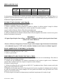
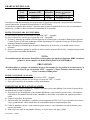
GAS SETTINGS:
GAS
TYPE
BTU/hr per burner
(kW)
Orifice
Size
Manifold Pressure (
w.c.)
Natural 15,000 (4.4) 5/64 “ 4.5 inches (11.4 cm)
Propane 15,000 (4.4) 1.15 mm 10 inches (25.4 cm)
Orifices are sized to provide proper gas flow at the above manifold pressures to provide 15,000 BTU/hr.
Regulator pressure must be measured and adjusted before the unit goes into service, following installation
and when operational performance is in question.
LIGHTING INSTRUCTIONS:
A. Turn all thermostat knobs to the “OFF” position.
B. Turn gas shut off valve to “ON” position.
C. Press and hold left pilot button and light left pilot. With pilot burning, keep pilot knob depressed
for 45 seconds or until pilot remains lit automatically.
D. Repeat previous step for right hand pilot, if present.
E. Operate thermostats by turning knobs clockwise and insure that burners light properly.
NOTE
If appliance contains more than one pilot, the left-most pilot MUST be lit first or
other pilot WILL NOT LIGHT.
CAUTION
If pilot(s) extinguish or gas supply is interrupted, turn thermostat knobs and the gas
shut off valve to the “OFF” position and wait 5 minutes before attempting to relight.
SHUTTING DOWN:
A. Turn thermostat knobs to the “OFF” position.
B. Turn gas shut off valve to “OFF” position.
C. Allow griddle surface to cool normally.
FINAL INSTALLATION STEPS:
New griddles should be carefully tempered and cared for in order to avoid possible damage. To break in a
new griddle, do the following:
A. Ensure that a proper installation has been performed on the appliance and that all warnings,
cautions, and notices contained in this manual have been read, understood and adhered to before
proceeding.
B. Wipe the griddle surface clean.
C. Light all the griddle burners and turn them to 200°F for one hour. Then, gradually bring each
griddle up to frying temperature.
D. Spread three or four ounces of beef suet, or as a substitute, baking soda, over griddle plate to
season it. Never allow water on a hot griddle and never wash it with soap and water.
E. Check (and, if necessary, adjust) the thermostats that control the griddle’s surface temperature.

L25-012 Rev 1 (08/02) 6
THERMOSTAT ADJUSTMENT PRODECURE:
Each control operates a pair of burners via a snap action thermostatic valve. This control was adjusted at
the factory. However, if the griddle’s surface temperature varies greatly from the setting on the thermostat
knob adjust the thermostat using the following procedure:
A. Light pilots per lighting instructions.
B. Turn al the control knobs to the 300°F setting.
C. Wait 30 minutes (or 1 hour if griddle was cold) for surface to stabilize.
D. Place a reliable thermometer or test instrument thermocouple (able to register 300°F) halfway
back from the front to the back of the griddle plate and directly over a burner set (in line with a
burner control knob). Check the temperature over each burner set every 5 minutes until the
temperature over each burner set stabilizes and does not change by more than 30°F between two
consecutive measurements.
E. If the average temperature over any burner set is not within 30°F of the knob setting (300°F),
adjust the corresponding thermostat by removing the knob, holding the thermostat stem (do not
allow stem to turn or temperature setting will be changed) and turning the small screw located
within the base of the stem. Turn this screw counter clockwise to increase the temperature,
clockwise to decrease the temperature.
DAILY CLEANING , MAINTENANCE AND SERVICING
CLEANING AND SEASONING - Your new MagiKitch'n Griddle is preserved with pure soybean oil
shortening after manufacture. There are two popular methods to remove the preservative
shortening. One method is to wash the griddle down with hot water and dishwashing detergent,
rinse thoroughly in hot water and then dry the griddle immediately to avoid rust spots. The second
method is to cook the shortening off. When all the shortening is gone, the griddle should be
allowed to cool to a temperature where it can be safely wiped down with a wet cloth or sponge
until clean.
Lastly, you’ll want to season the griddle as you would a good iron skillet or conventional griddle.
The griddle is ready to begin cooking.
OUTER SIDES AND FRONT - The outer sides and front are stainless steel. Any reputable cleaner can be
used to clean these surfaces.
GREASE TUB – The grease tub is designed to contain grease run off from the griddle surface. The grease
tub should never be allowed to overfill, and should be emptied daily and the grease disposed of
properly.
MAINTAINING a clean, well-kept griddle will ensure long-lasting cooking performance and prolong its
life.
SERVICING Contact the factory, ASAP service representative or local service company to perform
maintenance and repairs.
509 Route 3A
Bow, NH 03304
Voice (603) 225-6684
Toll Free (800) 258-3708
FAX (603) 225-8472
WWW.MAGIKITCHN.COM
Page is loading ...
Page is loading ...
Page is loading ...
Page is loading ...
Page is loading ...
Page is loading ...
Page is loading ...
Page is loading ...

MAGIKITCH’N
P.O. BOX 501
CONCORD NH 03302-0501
509 ROUTE 3A
BOW NH 03304
Teléfono (603) 225-6684
800-258-3708
FAX 603-225-8497
www.magikitchn.com
MKG 24, 36, 48, 60, 72
PLANCHA DE GAS PARA COCINA
INSTRUCCIONES DE INSTALACION Y OPERACIÓN
L25-012 Rev 1 (08/02)
Page is loading ...
Page is loading ...
Page is loading ...
Page is loading ...
Page is loading ...
Page is loading ...
Page is loading ...
-
 1
1
-
 2
2
-
 3
3
-
 4
4
-
 5
5
-
 6
6
-
 7
7
-
 8
8
-
 9
9
-
 10
10
-
 11
11
-
 12
12
-
 13
13
-
 14
14
-
 15
15
-
 16
16
-
 17
17
-
 18
18
-
 19
19
-
 20
20
-
 21
21
-
 22
22
-
 23
23
-
 24
24


Magikitchn MKG48 User manual
- Category
- Electric griddles
- Type
- User manual
Ask a question and I''ll find the answer in the document
Finding information in a document is now easier with AI
in other languages
- français: Magikitchn MKG48 Manuel utilisateur
- español: Magikitchn MKG48 Manual de usuario
Related papers
-
Magikitchn MKG48 Operating instructions
-
-
-
Magikitchn MKGD72 Operating instructions
-
-
-
Magikitchn APM-RMB 600 SERIES User manual
-
-
Magikitchn MKG-ST Operating instructions
-
Other documents
-
Magikitch'n MKG72 User manual
-
American Standard 132433 Installation guide
-
Vulcan VCRG36-T Owner's manual
-
Vulcan-Hart 24RRG-ML-135339-00024 Specification
-
-
 M.K.E. INDUSTRIES L-36M Owner's manual
-
Vulcan 36S-6B Owner's manual
-
Vulcan VCCG60 Owner's manual
-
Garland M42 M42R M42T M42S Specification
-
Garland Sunfire X60-6R24RR User manual
