LG LT1035CER Owner's Manual English 6,358K
- Category
- Split-system air conditioners
- Type
- Owner's Manual English 6,358K

your air conditioner and retain it for future reference.
TYPE WINDOW
MODELS LT1035CER,LT1235CER
MFL68743902

2 Room Air Conditioner
Window-Type Air Conditioner Owner’s Manual
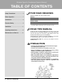
TABLE OF CONTENTS
FOR YOUR RECORDS
Write the model and serial numbers here:
Model #
Serial #
You can find them on a label on the side of each unit.
Dealer's Name
Date Purchased
■ Staple your receipt to this page in the event you need it
to prove date of purchase or for warranty issues.
READ THIS MANUAL
Inside you will find many helpful hints on how to use and
maintain your air conditioner properly. Just a little preventive
care on your part can save you a great deal of time and
money over the life of your air conditioner.
You'll find many answers to common problems in the chart
of troubleshooting tips. If you review our chart of
Troubleshooting Tips first,youmaynotneedtocallfor
service at all.
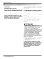
PRECAUTION
• Contact the authorized service technician for repair
or maintenance of this unit.
• Contact the installer for installation of this unit.
• The air conditioner is not intended for use by young
children or invalids without supervision.
• Young children should be supervised to ensure that
they do not play with the air conditioner.
• When the power cord is to be replaced, replacement
work shall be performed by authorized personnel only
using only genuine replacement parts.
• Installation work must be performed in accordance
with the National Electric Code by qualified and
authorized personnel only.
Safety Precautions..........................3
Before Operation.............................7
Introduction ....................................8
Electrical Safety ..............................9
Installation ....................................11
Operating Instructions .................18
Maintenance and Service ............21

Owner’s Manual 3
ENGLISH
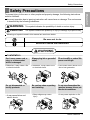
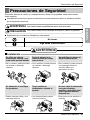
Safety Precautions
Safety Precautions
To prevent injury to the user or other people and property damage, the following instructions
must be followed.
Incorrect operation due to ignoring instruction will cause harm or damage. The seriousness
is classified by the following indications.
Meanings of symbols used in this manual are as shown below.
WARNING
CAUTION
This symbol indicates the possibility of death or serious injury.
This symbol indicates the possibility of injury or damage to properties only.
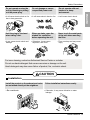
WARNING
Installation
Be sure not to do.
Be sure to follow the instruction.
Don’t use a power cord, a
plug, or a loose socket
which is damaged.
• Otherwise, it may cause a fire
or electrical shock.
Always plug into a grounded
outlet.
• Otherwise, it may cause a fire
or electrical shock.
Do not modify or extend the
power cord length.
• It will cause electric shock or fire
due to heat generation.
Always plug into a grounded
outlet.
Do not modify or extend the
power cord length.
Gasolin
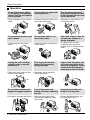
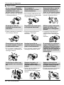
Do not disassemble or
modify products.
• It may cause failure and
electric shock.
Be caution when unpacking
and installing.
• Sharp edges may cause
injury.
Do not store flammables like
gasoline, benzene, thinner, etc.
near the air conditioner.
• It may cause explosion or fire.

4 Room Air Conditioner
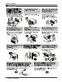
Operation
Do not place the power cord
near a heater.
• It may cause fire and electric
shock.
Do not allow water to run
into electric parts.
• It will cause failure of machine or
electric shock.
Use a soft cloth to clean. Do
not use wax, thinner, or a
strong detergent.
• The appearance of the air
conditioner may deteriorate,
change color, or develop surface
flaws.
Wax
Thinner
No correlation between fan
usage and oxygen depletion.
• An oxygen shortage may occur.
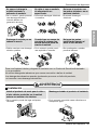
Turn off the power and
breaker first when cleansing
the unit.
• Since the fan rotates at high
speed during operation, it may
cause injury.
Unplug the unit when not
using it for a long time.
• Prevent accidental startup and
the possibility of injury.
Unplug the unit if strange
sounds, odors, or smoke
come from it.
• Otherwise it may cause fire and
electric shock accident.
Do not open the suction
inlet grill of the product
during operation.
• Otherwise, it may electrical
shock and failure.
If water enters the product, turn
off the the power switch of the
main body of appliance. Contact
service center after taking the
power-plug out from the socket.
Do not place heavy object
on the power cord and take
care so that the cord should
not be pressed.
• There is danger of fire or electric
shock.
Do not share the outlet with
other appliances.
• It will cause electric shock or fire
due to heat generation.
Take the power plug out if
necessary, holding the head
of the plug and do not touch
it with wet hands.
• Otherwise, it may cause a fire
or electrical shock.
Safety Precautions

Owner’s Manual 5
ENGLISH
Safety Precautions
CAUTION
Installation
Do not operate or stop the
unit by inserting or pulling
out the power plug.
• It will cause electric shock or fire
due to heat generation.
Do not damage or use an
unspecified power cord.
• It will cause electric shock or fire.
Do not operate with wet
hands or in damp
environment.
• It will cause electric shock.
Hold the plug by the head
when taking it out.
• It may cause electric shock and
damage.
When gas leaks, open the
window for ventilation
before operating the unit.
• Otherwise, it may cause
explosion, and a fire.
Never touch the metal parts
of the unit when removing
the filter.
• They are sharp and may cause
injury.
For inner cleaning, contact an Authorized Service Center or a dealer.
Do not use harsh detergent that causes corrosion or damage on the unit.
Harsh detergent may also cause failure of product, fire, or electric shock.
Install the product so the exhaust and noise
are not aimed directly at the neighbors.
• Be considerate.
Follow installation instructions exactly.
• Otherwise, it may cause vibration or water
leakage.

y
If you eat the liquid from the battery,brush
your teeth and see doctor.Do not use the
remote if the battery have leaked.
y
If the liquid from the battery gets onto your skin
or clothers
wash it well with clean water. Do
not use the remote if the battery has leaked.
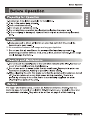
Instead of running air conditioning
constantly
open a window
for fresh air occasionally.
You will feel better.
Do not use this appliance for
special purposes such as
cooling pets,
foods, precision
machinery, or objects of art.

7
2. No correlation between fan usage and oxygen depletion.
3.

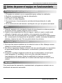
8 Room Air Conditioner
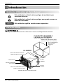
Introduction
This symbol alerts you to the risk of electric shock.
This symbol alerts you to hazards that could cause harm to
the air conditioner.
This symbol indicates special notes.
NOTICE
This appliance should be installed in accordance with the National Electric Code.
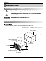
Introduction
Symbols Used in this Manual
Features
CABINET
FRONT GRILLE
INLET GRILLE
(Air Intake)
AIR FILTER
HORIZONTAL AIR DEFLECTOR
(Vertical Louver)
VENT CONTROL
VERTICAL AIR DEFLECTOR
(Horizontal Louver)
AIR DISCHARGE
SLEEVE ASSEMBLY
(Including Aluminum Rear grille)
THE SLEEVE AND THE REAR GRILLE
(optionally supplied with your unit)
THE UNIT
REAR GRILLE
(Aluminum Rear grille)

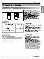
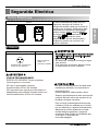
Avoid shock hazard. This unit cannot
be user-serviced. Do NOT open the
tamper-resistant sealed portion.
All warranties and performance will
be voided. This unit is not intended
to be used as an ON/OFF switch.
USE OF EXTENSION CORDS
RISK OF FIRE could cause serious injury or death
DO NOT use an extension cord with this window
air conditioner
DO NOT use surge protectors or multi-outlet
adapters with this window air conditioner
should
be
RESET
TEST
9

10

Owner’s Manual 11
ENGLISH
Installation
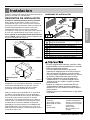
Installation
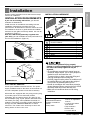
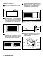
Remove packing materials from the wall sleeve and tape
from the air conditioner.
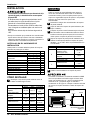
INSTALLATION REQUIREMENTS
If you use an existing wall sleeve, you should
measure its dimensions.
Install the new air conditioner according to these
installation instructions to achieve the best
performance. All wall sleeves used to mount the new
air conditioner must be in good structural condition
and have a rear grille to securely attach the new air
conditioner. (Figure 1)
With the LGE sleeve(optionally supplied with
your unit), you can maintain the best performance of
the new air conditioner. (Figure 2)
ELECTRICAL SERVICE
Check your available electrical service. The power
supply available must be the same as that shown on
the unit nameplate (found on left side of cabinet).
All models are equipped with a 3-prong service plug
to provide proper service and safe positive
grounding. Do not change plug in any way. Do not
use an adapter plug. If your present wall outlet does
not match your plug, call a qualified electrician to
make the necessary corrections. SA
VE CARTON for
storage and this OWNER'S MANUAL for future
reference. The carton is the best way to store unit
during winter or when not in use.
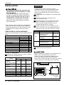
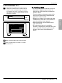
INSTALLATION HARDWARE
14-
13
/
32
"
(366 mm)
24"(610 mm)
18-
15
/
32
"(468 mm)
20-
3
/
32
"
(511 mm)
1
5
6
7
8
3
2 4
9
2 Size options
2 Size options
To avoid risk of personal injury, property
damage, or product damage due to the weight of
this device and sharp edges that may be
exposed:
• Air conditioners covered in this manual pose an
excessive weight hazard. Two or more people are
needed to move and install the unit.
To prevent injury or strain, use proper lifting and
carrying techniques when moving unit.
• Carefully inspect location where air conditioner will
be installed. Be sure it will support the weight of
the unit over an extended period of time.
• Handle air conditioner with care. Wear protective
gloves whenever lifting or carrying the unit. AVOID
the sharp metal fins of front and rear coils.
• Make sure air conditioner does not fall during
installation.
REQUIRED TOOLS:
• Tight Fitting gloves
• Standard screwdriver
• Phillips screwdriver
• Pliers
• Sharp knife
• 3/8-inch open end
wrench or adjustable
wrench
• 1/4-inch hex socket
and ratchet
• Tape measure
• Electric drill
• 1/4-inch drill bit
Figure 1
Air Conditioner
ITEM NAME OF PARTS Q'TY
1 PLASTIC GRILLE 1
2 VERTICAL INSULATION STRIP 1
3 AROUND INSULATION STRIPS 2
4 HORIZONTAL INSULATION STRIP 1
5 SUPPORT BLOCK 2
6 BAFFLE 1
7 TRIM FRAME 2
8 SHIM 2
9
PLASTIC NUTS AND WASHER SCREWS
4
15-
17
/
32
"
(394 mm)
16-
23
/
32
"
(425 mm)
25-
7
/
8
"
(656 mm)
Aluminum metal grille
Figure 2
LGE Wall Sleeve

12 Room Air Conditioner
Installation
ITEM (inches) Qty.
Plastic grille 26
3
/
4
x 16
1
/
2
1
Vertical insulation strip 15
9
/
16
x 1
3
/
8
x 1
3
/
8
1
Around Insulation Strips
67
1
/
8
x 1
3
/
8
x
25
/
32
1
59
27
/
32
x 1
3
/
8
x 1
3
/
8
1
Horizontal Insulation Strip 23
7
/32
x 1
3
/
8
x 1
3
/16
1
Support Block 1
3
/
4
x 1
3
/
8
x 4
5
/
16
2
Baffle
14 x
4
1
/
2
x
1
/
8
1
Shim x 1 x
3
/
4
2
Trim Frame 2
Washer Screw 4
Nuts (Plastic) 4
Grille Rear 1
8
1
/
2
INSTALLATION
• Pick a location which will allow the conditioned air
to blow into the area you want. Good installation
with special attention to the proper position of the
unit will lessen the chance that service will be
needed.
ITEMS IN INSTALLATION HARDWARE
You may not need all parts in the kit. Discard unused
parts.
HOW TO INSTALL
Identify the existing wall sleeve before installing
the unit from the listed below.
All wall sleeves used to mount the new air
conditioner must be in sound structural condition
and have a rear grille that securely attaches to
sleeve, or rear flange that serves as a stop for the
air conditioner.
Remove the old airconditioner from existing wall
sleeve.
Clean the interior of the existing sleeve.
(Do not disturb seals.)
Wall sleeve must be securely fastened in wall
before installing the air conditioner. Use the
nails or screws through sleeve into wall, if
needed. Repaint sleeve if needed.
Prepare the wall sleeve for installation of the
unit. If you plan to use your existin
g wall sleeve,
and it is not LGE, use procedure B or C below.
Install new unit into wall sleeve.
When installation is completed, the replacement unit
MUST have a rearward slope as shown. To
achieve 1/4" slope, remove the backing from the
8-1/2" shim strips and attach them as shown
below in Fig. 3. Place the higher portion of the shim to
the front of the rib on the base of the wall sleeve.
NOTICE
1
2
3
4
5
6
1/4"
Wall Sleeve
FRONT
UNIT
SHIM PLACEMENT UNIT INSTALLATION
1" high
3
/
4
" High
Shim
6" 6"
Figure 3
We strongly recommend the removal of the
old wall sleeve and the installation of a new
LGE Wall Sleeve.
If you decide to keep the existing wall sleeve,
you have to redirect the louvers at the back of
the wall sleeve illustration. The use of pliers is
recommended. If you DO NOT redirect, you
run the risk of poor performance or product
failure. This is not covered under the terms of
the LGE warranty.
Wall Sleeve Dimensions (inches)
Brand
Width Height Depth
White-Westinghouse
25-1/2 15-1/4
16, 17-1/2
Frigidaire
or 22
Carrier (52F series)
General Electric
26 15-5/8 16-7/8
/Hotpoint
Whirlpool 25-7/8 16-1/2
17-1/8
or 23
Fedders/Emerson 27 16-3/4
16-3/4
or 19-3/4
LGE 25-7/8 15-17/32 16-23/32
Emerson/Fedders 26-3/4 15-3/4 15
Carrier (51S Series) 25-3/4 16-7/8 18-5/8
Friedrich 27 16-3/4 16-3/4
Procedure Brand
Depth(inches)
A LGE 16-23/32
White-Westinghouse
Frigidaire Carrier
16, 17-1/2
(52F series)
or 22
B
General Electric
16-7/8
/Hotpoint
Whirlpool 17-1/8 or 23
Carrier (51S series)
18-5/8
Fedders/Emerson
16-3/4
or 19-3/4
C
Emerson/Fedders 15
Friedrich 16-3/4

Owner’s Manual 13
ENGLISH
Installation
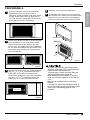
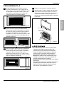
PROCEDURE A
If you are using the new sleeve (optionally
supplied with your unit), skip to step 3.
Otherwise, install the plastic grille from the kit.
Cut the plastic grille to 25-1/2" wide and 15-
1/4" high. Place the plastic grille to the inside
of the wall sleeve at the rear flange.
Fasten the 4 washer screws to secure the grille
to the wall sleeve. If you need plastic nuts to
mount plastic grille to the inside of the wall
sleeve, there are plastic nuts in the installation
kit. The nuts are installed from the inside of the
sleeve and are pressed into the square holes
of the rear flanges.
Remove the backing from the vertical insulation
strip 15
9
/
16
x 1
3
/
8
x 1
3
/
8
and attach that to the
inside right of the sleeve as shown below.
Remove the backing from the around insulation
strip 67
1
/
8
x 1
3
/
8
x
25
/
32
and attach that to the
inside front of the sleeve as shown below.
Install the new unit into the wall sleeve.
To assemble trim,
snap the tab of each piece
into the slot of the other piece as shown below.
Slide trim over the front of the air conditioner
until trim is flush with sleeve as shown below.
ENGLISH
Figure 4
Around Insulation
Vertical Insulation
9
1
/
2
" 6"
Indoor Outdoor
Figure 6
or
Figure 5
1
2
3
5
Wall
Trim (2 ea)
7 erugiF
• Air conditioners covered in this manual pose an
excessive weight hazard. Two or more people are
needed to move and install the unit.
To prevent injury or strain, use proper lifting and
carrying techniques when moving unit.
• When handling the air conditioner, be careful to
avoid cuts from sharp metal fins on front and rear
coils.
• Make sure air conditioner does not fall during
removal.
• If unit does not operate after installation check, to
be sure the circuit interrupter has not been tripped.
Refer to the Troubleshooting guide for reset
procedure.
4

14 Room Air Conditioner
Installation
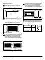
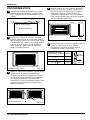
PROCEDURE B
Redirect the louvers at the back of the wall
.8 erugiF ni nwohs sa elgna °06 ot eveels
The use of pliers is recommended.
If the wall sleeve already has a rear grille, skip
to step 4. If the wall sleeve does not have a rear
grille or louvered panel, install the plastic grille
from the kit. Cut the plastic grille to 25-1/2" wide
and 15-1/4" high. Place the plastic grille to the
inside of the wall sleeve at the rear flange.
Fasten the 4 washer screws to secure the grille
to the wall sleeve. If you need plastic nuts to
mount plastic grille to the inside of the wall
sleeve, there are plastic nuts in the installation
kit. The nuts are installed from the inside of the
sleeve and are pressed into the square holes of
the rear flanges.
Remove the backing from the Vertical Insulation
strip 15
9
/
16
x 1
3
/
8
x 1
3
/
8
and attach that to the
inside right of the sleeve as shown below.
Remo
ve the backing from the Around Insulation
strip 67
1
/
8
x 1
3
/
8
x
25
/
32
and attach that to the
inside front of the sleeve as shown below.
If the depth of your existing wall sleeve is less
than or equal to 18", skip to step 6. Otherwise,
cut the baffles and the support blocks according
to length A in the table below.
Figure 8
Depth D of the existing
wall sleeve (inches)
Length A
(inches)
Support
Block
Baffle
A
A
3
/4
1-
3
/4
4
18 D 18-
5
/
8
18-
5
/
8
D 19-
3
/
4
19-
3
/
4
D 22
5
Place the plastic grille
Fasten the screws
Figure 12
1
4
2
3
Figure 9
Around Insulation
Vertical Insulation
9
1
/
2
" 6"
Indoor Outdoor
Figure 11
or
Figure 10
Rear Louvers
(Top View)
60°
60°
7
3
/
32
"

Owner’s Manual 15
Installation
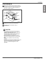
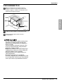
PROCEDURE B
Remove the backing from the support blocks
and attach them to the inside of the wall sleeve
as shown Figure 13 . Slide the baffle into
slots of the support blocks.
Install the new unit into the wall sleeve.
Assemble trim as described in Step 5,
Procedure A.
Wall
Wall
Sleeve
Baffle
(
7
3
/
32
"
)
Front
Support
Block
Figure 13
6
in
7
CAUTION
• Air conditioners covered in this manual pose an
excessive weight hazard. Two or more people are
needed to move and install the unit.
To prevent injury or strain, use proper lifting and
carrying techniques when moving unit.
• When handling the air conditioner, be careful to
avoid cuts from sharp metal fins on front and rear
coils.
• Make sure air conditioner does not fall during
removal.
• If unit does not operate after installation check, to be
sure the circuit interrupter has not been tripped.
Refer to the Troubleshooting guide for reset
procedure.
8

16 Room Air Conditioner
Installation
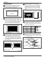
PROCEDURE C
Redirect the louvers at the back of the wall
sleeve to 60° angle as shown in Figure 14.
The use of pliers is recommended.
If the wall sleeve already has a rear grille, skip
to step 4. If the wall sleeve does not have a rear
grille or louvered panel, install the plastic grille
from the kit. Cut the plastic grille to 26-1/2" wide
and 15-1/2" high. Place the plastic grille to the
inside of the wall sleeve at the rear flange.
Fasten the 4 washer screws to secure the grille
to the wall sleeve. If you need plastic nuts to
mount plastic grille to the inside of the wall
sleeve, there are plastic nuts in the installation
kit. The nuts are installed from the inside of the
sleeve and are pressed into the square holes of
the rear flanges.
Remove the backing from the horizontal
insulation strip 23
7
/
32
x 1
3
/
8
x 1
3
/
16
and attach
that to the inside right of the sleeve as shown
belo
w. Remove the backing from the around
insulation strip 59
27
/
32
x 1
3
/
8
x 1
3
/
8
and attach
that to the inside front of the sleeve as shown
below.
If the depth of your existing sleeve is less than
or equal to 18”, skip to step 7. Otherwise, cut
the baffles and the support blocks according to
Length A in the table below.
Remove the backing from the support blocks
and attach them to the inside of the wall sleeve
as shown in Figure 19.
Slide the baffle into slots
of the support blocks
Depth D of the existing
wall sleeve (inches)
Length A
(inches)
Support
Block
Baffle
A
A
3
/4
1-
3
/4
4
18 D 18-
5
/
8
18-
5
/
8
D 19-
3
/
4
19-
3
/
4
D 22
Wall
Wall
Sleeve
Baffle
Front
Support
Block
(7
3
/
32
")
Figure 19
Figure 18
1
4
2
3
Figure 15
8
1
/
2
"
Indoor Outdoor
Around Insulation
Horizontal Insulation
Figure 17
or
Figure 16
Rear Louvers
(Top View)
60°
7
3
/
32
"
60°
Figue 14
5
6
Place the plastic grille
Fasten the screws

Installation
Owner’s Manual 17
8
9
7
Figure 20
Install the new unit into the wall sleeve.
Assemble trim as described in Step 6,
Procedure A.
To achieve rearward slope for unit draining,
remove the backing from the 8
1
/
2
" shim
strips and attach them as shown below in Figure
21. The higher portion of shim is to be placed
in front of the rib on the base of wall sleeve.
Figure 21
1" high
3
/
4
" High
Shim (2EA)
6" 6"
• Air conditioners covered in this manual pose an
excessive weight hazard. Two or more people are
needed to move and install the unit.
To prevent injury or strain, use proper lifting and
carrying techniques when moving unit.
• When handling the air conditioner, be careful to avoid
cuts from sharp metal fins on front and rear coils.
• Make sure air conditioner does not fall during
removal.
• If unit does not operate after installation check, to be
sure the circuit interrupter has not been tripped.
Refer to the Troubleshooting guide for reset
procedure.

18 Room Air Conditioner
Operating Instructions
Operating Instructions
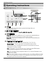
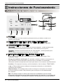
REMOTE CONTROLLER
Power
Temp
Fan Speed
Timer Mode
- when the air conditioner is off, it can be set to automatically turn
Delay OFF
- when the air conditioner is on, it can be set to automatically turn
on from 1 to 24 hours at its previous mode and fan settings.
off from 1 to 24 hours.
Delay ON
ON/OFF TIMER
Operation starts when this button is pressed and stops when you
press the button again.
FAN SPEED SELECTOR
Use to set the fan speed to
Low (F1), MED (F2), High (F3).
POWER
OPERATION MODE SELECTOR
the desired fan speed.
Cool - Compressor runs and cools the room. Use the
and FAN buttons
to set the desired temperature and circulation fan speed.
Energy Saver - The fan stops when the compressor stops cooling.
Approximately every 3 minutes the fan will turn on and check the room air
temperature if cooling is needed.
Fan - Fan circulates air but compressor does not run. Use the FAN button to set
Push the MODE button to rotate between Energy Saver / Cool / Fan / Dry.
7
Once the set temperature is reached the compressor and circulation fan turns off.
Dry
- Dry mode is used to remove humidity from the room without additional cooling.
Fan speed is pre-set and cannot be adjusted.

Owner’s Manual 19
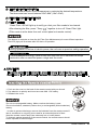
TEMPERATURE CONTROL
The thermostat monitors room temperature to maintain the desired temperature.
The thermostat can be set between 60
F~86 F (16 C~30 C).
REMOTE CONTROL SENSOR
CLEAN FILTER
7
After cleaning the filter, press “Temp ”
together to turn off ‘Clean Filter’ light.
(Filter reset must be done from unit control panel not remote control).
The unit defaults to Energy Saver mode each time the unit is switched on except
restoration after an electrical power outage and fan mode.
ENERGY SAVER
‘Clean Filter’ LED will light up to notify you that your filter needs to be cleaned.
During operation in failure of electric power, the unit runs as previous setting operation.
This feature is reminder to clean the Air Filter (See Maintenance) for more efficient operation.
The LED (light) will illuminate after 250 hours of operation.
ENERGY SAVER
CAUTION
Do not ure rechargeable battery. Make sure that the battery is new.
Do not mix alkaline, standard (Carbon-zinc) or rechargeable (Nickel-cadmium)
battery.
- In order to prevent discharge, remove the batteries from the remote control if
the air conditioner is not going to be used for an extended period of time.
To maintain optimal operation of the remote control, the remote sensor should
not be exposed to direct sunlight.
Keep the remote control away from extremely hot or humid places.
1. Push out the cover on the back of the remote control with your thumb.
2. Pay attention to polarity and insert one new AAA 1.5V battery.
3. Reattach the cover.
The remote controller will not function properly if strong light strikes the sensor of the air
conditioner or if there are obstacles between the remote controller and the air conditioner.
Battery

20 Room Air Conditioner
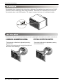
Operating Instructions
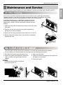
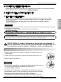
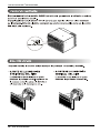
The ventilation lever is located in the right of the air discharge.The ventilation lever must be in the CLOSE
The direction of air can be controlled wherever you want by adjusting the horizontal louver and the vertical louver.
• HORIZONTAL AIR-DIRECTION CONTROL
posotion in order to maintain the best cooling conditions When fresh air is necessary in the room, set
the ventilation lever to the OPEN position. The damper is opened and room air is exhausted outside.
The horizontal air direction is adjusted by moving
vertical louver.
The lever of vertical louver is located in the right and
left side of the air discharge.
• VERTICAL AIR-DIRECTION CONTROL
The vertical air direction is adjusted by moving
the horizontal louver.
Page is loading ...
Page is loading ...
Page is loading ...
Page is loading ...
Page is loading ...
Page is loading ...
Page is loading ...
Page is loading ...
Page is loading ...
Page is loading ...
Page is loading ...
Page is loading ...
Page is loading ...
Page is loading ...
Page is loading ...
Page is loading ...
Page is loading ...
Page is loading ...
Page is loading ...
Page is loading ...
Page is loading ...
Page is loading ...
Page is loading ...
Page is loading ...
Page is loading ...
Page is loading ...
Page is loading ...
Page is loading ...
-
 1
1
-
 2
2
-
 3
3
-
 4
4
-
 5
5
-
 6
6
-
 7
7
-
 8
8
-
 9
9
-
 10
10
-
 11
11
-
 12
12
-
 13
13
-
 14
14
-
 15
15
-
 16
16
-
 17
17
-
 18
18
-
 19
19
-
 20
20
-
 21
21
-
 22
22
-
 23
23
-
 24
24
-
 25
25
-
 26
26
-
 27
27
-
 28
28
-
 29
29
-
 30
30
-
 31
31
-
 32
32
-
 33
33
-
 34
34
-
 35
35
-
 36
36
-
 37
37
-
 38
38
-
 39
39
-
 40
40
-
 41
41
-
 42
42
-
 43
43
-
 44
44
-
 45
45
-
 46
46
-
 47
47
-
 48
48


LG LT1035CER Owner's Manual English 6,358K
- Category
- Split-system air conditioners
- Type
- Owner's Manual English 6,358K
Ask a question and I''ll find the answer in the document
Finding information in a document is now easier with AI
in other languages
- español: LG LT1035CER
Related papers
Other documents
-
LG Electronics LT1015CER User guide
-
-
Goldstar Air Conditioner LT1230CR User manual
-
-
-
Sears LT143CNR User manual
-
-
Friedrich US12B10 Owner's manual
-
-