Page is loading ...

Frymaster, a member of the Commercial Food Equipment Service Association, recommends
using CFESA Certified Technicians.
24-Hour Service Hotline 1-800-551-8633
05/2016
www.frymaster.com E-mail: [email protected]
*8196685*
Oil Conserving Fryer (OCF30)
™
Electric Series Fryers
Installation & Operation Manual

NOTICE
IF, DURING THE WARRANTY PERIOD, THE CUSTOMER USES A PART FOR THIS MANITOWOC
FOOD SERVICE EQUIPMENT OTHER THAN AN UNMODIFIED NEW OR RECYCLED PART
PURCHASED DIRECTLY FROM FRYMASTER DEAN, OR ANY OF ITS FACTORY AUTHORIZED
SERVICERS, AND/OR THE PART BEING USED IS MODIFIED FROM ITS ORIGINAL
CONFIGURATION, THIS WARRANTY WILL BE VOID. FURTHER, FRYMASTER DEAN AND ITS
AFFILIATES WILL NOT BE LIABLE FOR ANY CLAIMS, DAMAGES OR EXPENSES INCURRED BY
THE CUSTOMER WHICH ARISE DIRECTLY OR INDIRECTLY, IN WHOLE OR IN PART, DUE TO
THE INSTALLATION OF ANY MODIFIED PART AND/OR PART RECEIVED FROM AN
UNAUTHORIZED SERVICER.
NOTICE
This appliance is intended for professional use only and is to be operated by qualified
personnel only. A Frymaster Dean Factory Authorized Servicer (FAS) or other qualified
professional should perform installation, maintenance, and repairs. Installation, maintenance,
or repairs by unqualified personnel may void the manufacturer’s warranty. See Chapter 1 of
this manual for definitions of qualified personnel.
NOTICE
This equipment must be installed in accordance with the appropriate national and local codes of
the country and/or region in which the appliance is installed. See NATIONAL CODE
REQUIREMENTS in Chapter 2 of this manual for specifics.
NOTICE TO U.S. CUSTOMERS
This equipment is to be installed in compliance with the basic plumbing code of the Building
Officials and Code Administrators International, Inc. (BOCA) and the Food Service Sanitation
Manual of the U.S. Food and Drug Administration.
NOTICE
Drawings and photos used in this manual are intended to illustrate operational, cleaning and
technical procedures and may not conform to onsite management operational procedures.
NOTICE TO OWNERS OF UNITS EQUIPPED WITH CONTROLLERS
U.S.
This device complies with Part 15 of the FCC rules. Operation is subject to the following two
conditions: 1) This device may not cause harmful interference, and 2) This device must accept
any interference received, including interference that may cause undesired operation. While
this device is a verified Class A device, it has been shown to meet the Class B limits.
CANADA
This digital apparatus does not exceed the Class A or B limits for radio noise emissions as set
out by the ICES-003 standard of the Canadian Department of Communications.
Cet appareil numerique n’emet pas de bruits radioelectriques depassany les limites de classe A
et B prescrites dans la norme NMB-003 edictee par le Ministre des Communcations du Canada.
DANGER
Improper installation, adjustment, maintenance or service, and unauthorized alterations or
modifications can cause property damage, injury, or death. Read the installation, operating,
and service instructions thoroughly before installing or servicing this equipment.

DANGER
The front ledge of this appliance is not a step! Do not stand on the appliance. Serious injury
can result from slips or contact with the hot cooking oil.
DANGER
Do not store or use gasoline or other flammable liquids or vapors in the vicinity of this or any
other appliance.
DANGER
The crumb tray in fryers equipped with a filter system must be emptied into a fireproof container
at the end of frying operations each day. Some food particles can spontaneously combust if left
soaking in certain shortening material.
WARNING
Do not bang fry baskets or other utensils on the fryer’s joiner strip. The strip is present to seal
the joint between the fry vessels. Banging fry baskets on the strip to dislodge shortening will
distort the strip, adversely affecting its fit. It is designed for a tight fit and should only be
removed for cleaning.
DANGER
Adequate means must be provided to limit the movement of this appliance without depending
on or transmitting stress to the electrical conduit. A restraint kit is provided with the fryer. If
the restraint kit is missing contact your local KES.
DANGER
Prior to movement, testing, maintenance and any repair on your Frymaster fryer, disconnect
ALL electrical power from the fryer.
NOTICE
The instructions in this manual for using a bulk oil system for filling and discarding oil are for
an RTI and Frontline system. These instructions may not be applicable to other bulk oil
systems.
WARNING
This appliance is not intended for use by children under the age of 16 or persons with reduced
physical, sensory or mental capabilities, or lack of experience and knowledge, unless they have
been given supervision concerning use of the appliance by a person responsible for their
safety. Do not allow children to play with this appliance.
WARNING
If the electrical power supply cord is damaged, it must be replaced by a Frymaster Factory
Authorized Servicer or a similarly qualified person in order to avoid a hazard.

iv
OCF30
™
Series Electric Fryers
Installation and Operation Manual
TABLE OF CONTENTS
CHAPTER 1: Introduction
1.1 General ..................................................................................................................................... 1-1
1.2 Safety Information ................................................................................................................... 1-1
1.3 Computer Information .............................................................................................................. 1-2
1.4 European Community (CE) Specific Information ................................................................... 1-2
1.5 Installation, Operating, and Service Personnel ........................................................................ 1-2
1.6 Definitions ................................................................................................................................ 1-2
1.7 Shipping Damage Claim Procedure ......................................................................................... 1-3
1.8 Service Information .................................................................................................................. 1-3
CHAPTER 2: Installation Instructions
2.1 General Installation Requirements ........................................................................................... 2-1
2.1.1 Clearance and Ventilation ............................................................................................ 2-2
2.1.2 Electrical Grounding Requirements ............................................................................. 2-2
2.1.3 Australian Requirements .............................................................................................. 2-3
2.2 Power Requirements ................................................................................................................ 2-3
2.3 Positioning the Fryer ................................................................................................................ 2-4
2.4 Installing the JIB Cradle .......................................................................................................... 2-4
CHAPTER 3: Operating Instructions
3.1 Equipment Setup and Start-Up Procedures .............................................................................. 3-2
3.2 Operation .................................................................................................................................. 3-2
3.3 Oil Attendant™ Automatic Topoff .......................................................................................... 3-3
3.3.1 Install the Oil Reservoir ............................................................................................... 3-3
3.3.2 Routine Oil Changes .................................................................................................... 3-3
3.3.3 Bulk Oil Systems ......................................................................................................... 3-4
CHAPTER 4: Filtration Instructions
4.1 Preparing the Built-In Filtration System for Use ..................................................................... 4-1
4.1.1 Preparation for Use with Filter Paper or Filter Pad ....................................................... 4-1
4.1.2 Preparation for Use with Magnasol Filter Assembly .................................................... 4-2
4.2 Filtration ................................................................................................................................... 4-3
4.2.1 Operation of the Filter ................................................................................................... 4-3
4.3 Disassembly and Reassembly of the Magnasol Filter .............................................................. 4-5
4.4 Draining and Disposing of Waster Oil ...................................................................................... 4-6
CHAPTER 5: Preventive Maintenance
5.1 Cleaning the Fryer .................................................................................................................... 5-1
5.2 Daily Checks and Service ........................................................................................................ 5-1
5.2.1 Inspect Fryer for Damage ............................................................................................. 5-1
5.2.2 Clean Fryer Cabinet Inside and Out .............................................................................. 5-1
5.2.3 Clean the Built-in Filtration System ............................................................................. 5-1
5.3 Weekly Checks and Service ..................................................................................................... 5-2
5.3.1 Clean Frypot and Heating Elements ............................................................................. 5-2
5.3.2 Boiling Out the Frypot .................................................................................................. 5-2
5.3.3 Clean Detachable Parts and Accessories....................................................................... 5-3

v
5.4 Monthly Checks and Service ................................................................................................... 5-3
5.4.1 Check Controller Setpoint Accuracy ............................................................................ 5-3
5.5 Annual/Periodic System Inspection ......................................................................................... 5-3
5.5.1 Fryer .............................................................................................................................. 5-3
5.5.2 Built-In Filtration System ............................................................................................. 5-4
CHAPTER 6: Operator Troubleshooting
6.1 Introduction .............................................................................................................................. 6-1
6.2 Troubleshooting ....................................................................................................................... 6-2
6.2.1 Controller and Heating Problems ................................................................................. 6-2
6.2.2 Error Message and Display Problems ........................................................................... 6-2
6.2.3 Basket Lift Problems .................................................................................................... 6-3
6.2.4 Filtration Problems ....................................................................................................... 6-4
6.2.5 Auto Top Off Problems ................................................................................................ 6-4
6.2.6 Error Log Codes............................................................................................................ 6-5
6.2.7 High Limit Test ............................................................................................................. 6-5
Wiring Diagrams
See 8197224 OCF Electric Wiring Diagrams Manual
ADDENDUM A: Solid Shortening JIB Preparation Instructions
ADDENDUM B: Solid Shortening Melter Use Instructions
ADDENDUM C: Bulk Oil Instructions

1-1
OCF30
™
SERIES
ELECTRIC FRYERS
CHAPTER 1: INTRODUCTION
1.1 General
Read the instructions in this manual thoroughly before attempting to operate this equipment. This
manual covers all configurations of FPEL14 and FPEL17 variants. The fryers in this model family
have most parts in common, and when discussed as a group, will be referred to as “OCF30
™
Series
Electric” fryers.
Although similar in appearance to the RE Series Electric family of Electric fryers, the OCF30
™
Series Electric fryers with SMART4U
®
technology feature a low oil volume frypot with an optional
automatic oil top off system. The Euro-Look design incorporates a rounded topcap and a large
round drain, which ensures that fries and other debris, will be washed into the filter pan. Other
features, such as rotating elements and filtration system remain essentially unchanged. The OCF30
™
Series Electric fryers are controlled with a 3000 or CM3.5 computer. Fryers in this series come in
full- or split-vat arrangements, and can be purchased as two, three or four vat fryers.
1.2 Safety Information
Before attempting to operate your unit, read the instructions in this manual thoroughly.
Throughout this manual, you will find notations enclosed in double-bordered boxes similar to the
one below.
DANGER
Hot cooking oil causes severe burns. Never attempt to move a fryer containing hot
oil or to transfer hot oil from one container to another.
CAUTION boxes contain information about actions or conditions that may cause or result in a
malfunction of your system.
WARNING boxes contain information about actions or conditions that may cause or result in
damage to your system, and which may cause your system to malfunction.
DANGER boxes contain information about actions or conditions that may cause or result in
injury to personnel, and which may cause damage to your system and/or cause your system to
malfunction.
The OCF30™ series electric fryers incorporate a high-temperature detection feature which shuts off
power to the elements should the temperature controls fail.

1-2
1.3 Computer Information
This equipment has been tested and found to comply with the limits for a Class A digital device,
pursuant to Part 15 of the FCC rules. While this device is a verified Class A device, it has been
shown to meet the Class B limits. These limits are designed to provide reasonable protection against
harmful interference when the equipment is operated in a commercial environment. This equipment
generates, uses and can radiate radio frequency energy and, if not installed and used in accordance
with the instruction manual, may cause harmful interference to radio communications. Operation of
the equipment in a residential area is likely to cause harmful interference in which case the user will
be required to correct the interference at their own expense.
The user is cautioned that any changes or modifications not expressly approved by the party
responsible for compliance could void the user's authority to operate the equipment.
If necessary, the user should consult the dealer or an experienced radio and television technician for
additional suggestions.
The user may find the following booklet prepared by the Federal Communications Commission
helpful: "How to Identify and Resolve Radio-TV Interference Problems". This booklet is available
from the U.S. Government Printing Office, Washington, DC 20402, Stock No. 004-000-00345-4.
1.4 European Community (CE) Specific Information
The European Community (CE) has established certain specific standards regarding equipment of
this type. Whenever a difference exists between CE and non-CE standards, the information or
instructions concerned are identified by means of shadowed boxes similar to the one below.
CE Standard
Example of box used to distinguish CE and
Non-CE specific information.
1.5 Installation, Operating, and Service Personnel
Operating information for Frymaster equipment has been prepared for use by qualified and/or
authorized personnel only, as defined in Section 1.6. All installation and service on Frymaster
equipment must be performed by qualified, certified, licensed, and/or authorized installation
or service personnel, as defined in Section 1.6.
1.6 Definitions
QUALIFIED AND/OR AUTHORIZED OPERATING PERSONNEL
Qualified/authorized operating personnel are those who have carefully read the information in this
manual and have familiarized themselves with the equipment functions, or who have had previous
experience with the operation of the equipment covered in this manual.

1-3
QUALIFIED INSTALLATION PERSONNEL
Qualified installation personnel are individuals, firms, corporations, and/or companies which, either
in person or through a representative, are engaged in and are responsible for the installation of
electrical appliances. Qualified personnel must be experienced in such work, be familiar with all
electrical precautions involved, and have complied with all requirements of applicable national and
local codes.
QUALIFIED SERVICE PERSONNEL
Qualified service personnel are those who are familiar with Frymaster equipment and who have been
authorized by Frymaster, L.L.C. to perform service on the equipment. All authorized service
personnel are required to be equipped with a complete set of service and parts manuals, and to stock
a minimum amount of parts for Frymaster equipment. A list of Frymaster Factory Authorized
Servicers (FAS’s) is located on the Frymaster website at www.frymaster.com/service. Failure to
use qualified service personnel will void the Frymaster warranty on your equipment.
1.7 Shipping Damage Claim Procedure
What to do if your equipment arrives damaged:
Please note that this equipment was carefully inspected and packed by skilled personnel before
leaving the factory. Frymaster does not assume responsibility for damage or loss incurred in
transit. The freight company assumes full responsibility for safe delivery upon acceptance of the
equipment.
1. File Claim for Damages Immediately—Regardless of extent of damage.
2. Visible Loss or Damage—Be sure this is noted on the freight bill or express receipt and is signed
by the person making the delivery.
3. Concealed Loss or Damage—If damage is unnoticed until equipment is unpacked, notify the
freight company or carrier immediately and file a concealed damage claim. This should be done
within 15 days of date of delivery. Be sure to retain container for inspection.
1.8 Service Information
For non-routine maintenance or repairs, or for service information, contact your local Frymaster
Factory Authorized Servicer (FAS). Service information may also be obtained by calling the
Frymaster Technical Services Department at 1-800-551-8633 or 1-318-865-1711 or by e-mail at
[email protected]. The following information will be needed in order to assist you efficiently:
Model Number _________________________
Serial Number _________________________
Voltage ______________________________
Nature of the Problem ___________________
____________________________________
____________________________________
RETAIN AND STORE THIS MANUAL IN A SAFE PLACE FOR FUTURE USE.

2-1
OCF30
™
SERIES
ELECTRIC FRYERS
CHAPTER 2: INSTALLATION INSTRUCTIONS
2.1 General Installation Requirements
Proper installation is essential for the safe, efficient, trouble-free operation of this appliance.
Qualified, licensed, and/or authorized installation or service personnel, as defined in Section
1.6 of this manual, should perform all installation and service on Frymaster equipment.
Failure to use qualified, licensed, and/or authorized installation or service personnel (as
defined in Section 1.6 of this manual) to install or otherwise service this equipment will void
the Frymaster warranty and may result in damage to the equipment or injury to personnel.
Where conflicts exist between instructions and information in this manual and local or
national codes or regulations, installation and operation shall comply with the codes or
regulations in force in the country in which the equipment is installed.
Service may be obtained by contacting your local Frymaster Factory Authorized Servicer.
NOTICE
All fryers shipped without factory supplied cords and plug assemblies must be
hardwired using flexible conduit to the terminal block located on the rear of the fryer.
These fryers should be wired to NEC specifications. Hardwired units must include
installation of restraint devices.
DANGER
Adequate means must be provided to limit the movement of this appliance without
depending on or transmitting stress to the electrical conduit. A restraint kit is
provided with the fryer. If the restraint kit is missing contact your local KES.
NOTICE
If this equipment is wired directly into the electrical power supply, a means for
disconnection from the supply having a contact separation of at least 3-mm in all
poles must be incorporated in the fixed wiring.
NOTICE
This equipment must be positioned so that the plug is accessible unless other
means for disconnection from the power supply (e.g., a circuit breaker) is provided.
NOTICE
If this appliance is permanently connected to fixed wiring, it must be connected by
means of copper wires having a temperature rating of not less than 167°F (75°C).
NOTICE
If the electrical power supply cord is damaged, it must be replaced by a Frymaster
Dean Factory Authorized Service technician or a similarly qualified person in order
to avoid a hazard.

2-2
DANGER
This appliance must be connected to a power supply having the same voltage and
phase as specified on the rating plate located on the inside of the appliance door.
DANGER
All wiring connections for this appliance must be made in accordance with the wiring
diagram(s) furnished with the appliance. Refer to the wiring diagram(s) affixed to the
inside of the appliance door when installing or servicing this equipment.
DANGER
Frymaster appliances equipped with legs are for stationary installations. Appliances
fitted with legs must be lifted during movement to avoid damage to the appliance
and bodily injury. For movable installations, optional equipment casters must be
used. Questions? Call 1-800-551-8633.
DANGER
Do not attach an apron drainboard to a fryer. The fryer may become unstable, tip
over and cause injury. The appliance area must be kept free and clear of
combustible material at all times.
DANGER
Building codes prohibit a fryer with its open tank of hot oil being installed beside an
open flame of any type, including those of broilers and ranges.
In the event of a power failure, the fryer(s) will automatically shut down. If this occurs, turn the
power switch OFF. Do not attempt to start the fryer(s) until power is restored.
2.1.1 Clearance and Ventilation
This appliance must be kept free and clear of combustible material, except that it may be installed on
combustible floors.
A clearance of 6 inches (15cm) must be provided at both sides and back adjacent to combustible
construction. A minimum of 24 inches (61cm) should be provided at the front of the equipment for
servicing and proper operation.
WARNING
Do not block the area around the base or under the fryers.
2.1.2 Electrical Grounding Requirements
All electrically operated appliances must be grounded in accordance with all applicable national and
local codes, and, where applicable, CE codes. All units (cord connected or permanently connected)
should be connected to a grounded power supply system. A wiring diagram is located on the inside
of the fryer door. Refer to the rating plate on the inside of the fryer door for proper voltages.

2-3
2.1.3 Australian Requirements
To be installed in accordance with AS 5601, local authority, gas, electricity, and any other relevant
statutory regulations.
2.2 Power Requirements
Three (3) Phase Requirements
MODEL VOLTAGE
WIRE
SERVICE
MINIMUM WIRE
SIZE
AWG (mm)
AMPS
(per leg)
FPEL14 208 3 6 (4.11) 39
FPEL14 240 3 6 (4.11) 34
FPEL14 480 3 8 (2.59) 17
FPEL14 220/380 4 6 (4.11) 21
FPEL14 240/415 4 6 (4.11) 20
FPEL14 230/400 4 6 (4.11) 21
FPEL17 208 3 6 (4.11) 48
FPEL17 240 3 6 (4.11) 41
FPEL17 480 3 6 (4.11) 21
FPEL17 220/380 4 6 (4.11) 26
FPEL17 240/415 4 6 (4.11) 24
FPEL17 230/400 4 6 (4.11) 25
NOTICE
If this appliance is permanently connected to fixed wiring, it must be connected by
means of copper wires having a temperature rating of not less than 167°F (75°C).
DANGER
This appliance must be connected to a power supply having the same voltage and
phase as specified on the rating plate located on the inside of the appliance door.
DANGER
All wiring connections for this appliance must be made in accordance with the
wiring diagram(s) furnished with the appliance. Refer to the wiring diagram(s)
affixed to the inside of the appliance door when installing or servicing this
equipment.

2-4
2.3 Positioning the Fryer
DANGER
No structural material on the fryer should be altered or removed to accommodate
placement of the fryer under a hood. Questions? Call the Frymaster Dean Service
Hotline at 1-800-551-8633.
1. Once the fryer has been positioned at the frying station, use a carpenter’s level placed across the
top of the frypot to verify that the unit is level, both side-to-side and front-to-back.
To level fryers, adjust the casters being careful to ensure the fryer(s) are at the proper height in
the frying station.
When the fryer is leveled in its final position, install the restraints provided by the KES to limit
its movement so that it does not depend on or transmit stress to the electrical conduit or
connection. Install the restraints in accordance with the provided instructions. If the restraints are
disconnected for service or other reasons, they must be reconnected before the fryer is used.
DANGER
Adequate means must be provided to limit the movement of this appliance without
depending on or transmitting stress to the electrical conduit. A restraint kit is
provided with the fryer. If the restraint kit is missing contact your local KES.
DANGER
Hot oil can cause severe burns. Avoid contact. Under all circumstances, oil must be
removed from the fryer before attempting to move it to avoid oil spills, falls and
severe burns. This fryer may tip and cause personal injury if not secured in a
stationary position.
2. Close fryer drain-valve(s).
3. Clean and fill frypot(s) to the bottom oil level line with cooking oil. (See Equipment Setup and
Shutdown Procedures in Chapter 3.)
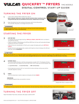
2.4 Installing the JIB Cradle
Open the fryer door (typically the far right door)
and remove the cross brace used for shipping
support by removing the four screws (see Figure
1). Install the JIB cradle shipped in the
accessories pack with the screws that were
removed in the cross brace removal step (see
Figure 2). If using the solid shortening option see
Appendix A in the rear of this manual for
installation instructions. Install the optional JIB
splash shield to protect the bottom of the JIB (see
Figure 3).
Figure 1 Figure 2
Figure 3

3–1
OCF30
™
SERIES ELECTRIC FRYER
CHAPTER 3: OPERATING INSTRUCTIONS
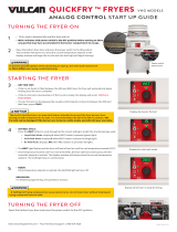
Tilt
Housing
Elements
Top Cap
Basket
Hanger
Drain
Handle
Bezel
Fuse
Optional JIB
(See Sec. 3.3)
Controller
(3000 Shown)
Filter Pan
FootPrint Pro Built-
In Filtration Unit
Power
Switch
(Domestic
Only)
Lift Rod
FINDING YOUR WAY AROUND THE OCF30
™
SERIES ELECTRIC FRYER
Filter
Handle
JIB reset
button
TYPICAL CONFIGURATION (FPEL214 SHOWN)
NOTE: The appearance of your fryer may differ slightly from that
shown depending upon the configuration and date of manufacture.

3–2
3.1 Equipment Setup and Shutdown Procedures
Setup
DANGER
Never operate the appliance with an empty frypot. The frypot must be filled to the fill line with
water or oil before energizing the elements. Failure to do so will result in irreparable damage
to the elements and may cause a fire.
DANGER
Remove all drops of water from the frypot before filling with oil. Failure to do so will cause
spattering of hot liquid when the oil is heated to cooking temperature.
WARNING
The OCF30™ with the automatic top off is NOT intended to use solid shortening. Use only
liquid shortening with this fryer. The use of solid shortening will clog the oil lines. The
cooking oil capacity of the OCF30™ Series electric fryer is 31 lbs. (3.7 gallons/14 liters) at
70°F (21°C).
DANGER
When using solid shortening, pack the shortening down into the bottom of the frypot. DO
NOT operate the fryer with a solid block of shortening sitting in the upper portion of the frypot.
This will cause damage to the frypot and may cause a flash fire.
Prior to filling frypots with oil ensure all drains are closed.
1. Fill the frypot with cooking oil to the bottom OIL LEVEL line located on the rear of the frypot. This will
allow for oil expansion as heat is applied. Do not fill cold oil any higher than the bottom line; overflow
may occur as heat expands the oil.
2. Ensure that the power cord(s) is/are plugged into the appropriate receptacle(s). Verify that the face of the
plug is flush with the outlet plate, with no portion of the prongs visible.
3. Ensure that the power is switched on. Some models are equipped with a master switch located behind the
fryer door cabinet on the front panel of the component box, next to the fuse. OFF is displayed on the
controller.
4. Ensure that the controller is switched ON. When the controller is switched on, the fryer will begin heating
and will display MLT-CYCL alternating with the temperature and setpoint until the fryer temperature
reaches 180°F (82°C). On CM 3.5 equipped fryers the display changes to LOW TEMP until within 15°F
of the setpoint. Then the display changes to product or dashed lines. On the 3000, once the fryer reaches
setpoint, the controller display changes to DROP and the fryer is ready for use. To exit the melt cycle on
the 3000, press the EXIT COOL button. Press YES to EXIT MELT?
5. Ensure that the oil level is at the top OIL LEVEL line when the oil is at its cooking temperature
.
Shutdown
1. Filter the oil and clean the fryers (See Chapters 5 and 6). If using a CM3.5 reverse steps 1 and 2.
2. Turn the fryer off.
3. Place the frypot covers on the frypots.
3.2 Operation
This fryer is equipped with either 3000 or CM3.5 controllers (illustrated on the following page). Fryers with
3000 controllers should refer to the 3000 Controller Manual 819-6872 for the controller programming and
operating procedure. For CM3.5 controllers refer to the separate Frymaster Fryer Controllers User’s Manual
furnished with your fryer for the specific controller operating instructions.

3–3
3000 CONTROLLER CM3.5
Refer to Chapter 4 of this manual for operating instructions for the built-in filtration system.
3.3 Optional Oil Attendant
®
Automatic Top-Off
When the Oil Attendant
®
top-off oil
system is in place on the fryer, oil is
continually topped off in the frypots from
a reservoir in the cabinet. The reservoir
holds a 35 pound box of oil. In a typical
operation this will last approximately two
days before changing. Components of the
system are annotated at the right (see
Figure 1).
NOTE: The system is intended to top
off the frypots, not fill them. The frypots
will require manual filling upon startup
and after disposal.
3.3.1 Install the Oil Reservoir
Remove the original lid from the oil container and foil liner. Replace with the provided cap, which has
connected suction hardware. Ensure the feeder tube from the cap reaches to the bottom of the oil
container.
Place the oil container inside the cabinet and slide it into place (as shown on the following page).
Avoid catching the suction hardware on the cabinet interior as the container is placed in the fryer.
The system is now ready for operation. As the fryer heats to preprogrammed temperatures, the system
will energize and then slowly add oil to the frypots as needed, until the oil reaches an optimal level.

3–4
3.3.2 Routine Oil Changes
When the oil reservoir level is low, the controller displays TOPOFF OIL EMPTY in the left display
and CONFIRM in the right display.
Press S (CONFIRM). Some procedures may differ from photos
shown. Follow manufacturer’s instructions for changing the JIB. If using solid shortening see Appendix B
in the rear of this manual for instructions.
1. Open the cabinet and slide the JIB
from the cabinet (see Figure 4).
Figure 4
2. Remove the cap and pour any remaining oil in the
container into all fry vats equally (see Figure 5).
Figure 5
3. With the jug upright remove the cap
and foil seal (see Figure 6).
Figure 6
4. Put the tube in the new full container (see Figure 7).
Figure 7
5. Slide the JIB onto the shelf inside the fryer cabinet (as
seen in Figure 4).
6. Press and hold the orange JIB reset switch three (3)
seconds to reset the top off system (see Figure 8).
Figure 8
Image and location may differ from photo.
3.3.3 Bulk Oil Systems
Instructions for installing and using bulk oil systems are found in Appendix C located
at the rear of this manual.
WARNING:
Do not add HOT or
USED oil to a JIB.

4-1
OCF30
™
SERIES ELECTRIC FRYERS
CHAPTER 4: FILTRATION INSTRUCTIONS
WARNING
The on-site supervisor is responsible for ensuring that operators are made aware of
the inherent hazards of operating a hot oil filtering system, particularly the aspects
of oil filtration, draining and cleaning procedures.
4.1 Preparing the Built-In Filtration System for Use
The FootPrint Pro filtration system allows the oil in one frypot to be safely and efficiently filtered
while the other frypots in a battery remain in operation. The FootPrint Pro filtration system is
available in three different configurations:
• Filter Paper – includes crumb tray, large hold-down ring, and metal filter screen.
• Filter Pad – includes crumb tray, small hold-down ring, and metal filter screen.
• Magnasol Filter – includes crumb tray and Magnasol filter assembly.
Section 4.1.1 covers preparation of the Filter Paper and Filter Pad configurations for use. Refer to
Section 4.1.2 for instructions on preparing the Magnasol Filter configuration for use. Operation of
all three configurations is the same and is covered in section 4.3. Disassembly and reassembly of the
Magnasol filter is covered in section 4.4.
4.1.1 Preparing the Built-In Filtration System for Use with Filter Paper or Filter Pad
The FootPrint Pro filtration system allows the oil in one frypot to be safely and efficiently filtered
while the other frypots in a battery remain in operation. The FootPrint Pro filtration system uses a
filter paper configuration which includes a crumb tray, large hold-down ring, and metal filter screen.
1. Pull the filter pan out from the cabinet and
remove the crumb tray, hold-down ring, filter
paper and filter screen (see Figure1). Clean
all components with a solution of detergent
and hot water then dry thoroughly.
The pan cover must not be removed except
for cleaning, interior access, or to allow a
shortening disposal unit (SDU) built before
January 2004 to be positioned under the
drain. Disposal instructions are on page 1-6
in the controller manual 819-6872.
Figure 1

4-2
2. Inspect the filter pan connection fitting to ensure that
both O-rings are in good condition (see Figure 2).
3. Then in reverse order, place the metal filter screen in
the center of the bottom of the pan, then lay a sheet of
filter paper on top of the screen, overlapping on all
sides (see Figure1). If using a filter pad, ensure the
rough side of the pad is up and lay the pad over the
screen, making sure that the pad is in between the
embossed ridges of the filter pan.
4. Position the hold-down ring over the filter paper and
lower the ring into the pan, allowing the paper to rest
on the sides of the filter pan (see Figure 3).
5. When the hold-down ring is in position, if using filter
paper, sprinkle one packet of filter powder evenly
over the paper. (See Figure 4)
6. Replace the crumb tray in the filter pan, then push the
filter pan back into the fryer, positioning it under the
drain.
Figure 2
Figure 3
Figure 4
4.1.2 Preparation for Use with the Magnasol Filter Assembly
1. Pull the filter pan out from the cabinet
and remove the crumb tray and
Magnasol filter assembly (see Figure 5).
Clean as directed in section 4.4
The pan cover must not be removed
except for cleaning, interior access, or to
allow a shortening disposal unit (SDU)
to be positioned under the drain.
NOTE: Refer to Section 4.4 for
instructions on how to disassemble and
reassemble the Magnasol filter screen
assembly.
2. Inspect the fitting on the bottom of the
Magnasol filter assembly to ensure that
the O-ring is present and in good
condition. (See Figure 6)
3. Inspect the filter pan connection fitting
to ensure that both O-rings are present
and in good condition. (See Figure 2
above).
4. Replace the Magnasol filter assembly in
the filter pan, ensuring that the fitting on
the bottom of the assembly is securely
seated in the port in the bottom of the pan.
Sprinkle one packet of the Magnasol XL filter
powder evenly over
the screen.
5. Replace the crumb tray, and then push the filter
pan back into the fryer, positioning it all the way
to the back of the cabinet.
Figure 5
Figure 6
Inspect the filter
screen O-ring.
Inspect the filter
connection fitting
O-rings.

4-3
4.2 Filtration
A 3000 controller prompts the user when to filter on the OCF30
™
fryer. After a preset number of
cook cycles the controller displays filter now? alternating with YES NO. Follow the
instructions on page 1-12 of the 3000 controller manual (819-6872). If NO is selected or a cook
cycle is started, the controller will prompt again soon to filter the oil.
On demand filtration is used to manually start a filter. See page 1-11 of the 3000 controller manual
(819-6872) for the filter menu.
The fryer MUST be at setpoint temperature for any filtration operation to start.
Note: Do NOT filter multiple vats simultaneously.
4.2.1 Operation of the Filter
DANGER
Draining and filtering of cooking oil must be accomplished with care to avoid the
possibility of a serious burn caused by careless handling. The oil to be filtered is at
or near 350°F (177°C). Ensure drain handles are in their proper position before
operating any switches or valves. Wear all appropriate safety equipment when
draining and filtering cooking oil.
DANGER
NEVER attempt to drain cooking oil from the fryer with the elements energized!
Doing so will cause irreparable damage to the frypot and may cause a flash fire.
Doing so will also void the Frymaster warranty.
1. Ensure that the filter is prepared. See Section. 4.1.
2. Make sure the oil is at operating temperature.
3. When prompted, drain the frypot into the filter pan by rotating the drain valve handle 90º (see
Figure 7). If necessary, use the Fryer's Friend clean-out rod to clear the drain from inside the
frypot.
Figure 7
DANGER
Do not drain more than one frypot at a time into the built-in filtration unit to avoid
overflow and spillage of hot oil that may cause severe burns, slipping and falling.
Open drain valve by rotating
90º. (Handles may differ from
photo.)

4-4
DANGER
NEVER attempt to clear a clogged drain valve from the front of the valve! Hot oil will
rush out creating the potential for severe burns.
DANGER
DO NOT hammer on the drain valve with the cleanout rod or other objects. Damage
to the ball inside will result in leaks and will void the Frymaster warranty.
4. After the oil has drained from the frypot
and when prompted, rotate the filter
handle towards the “I” to start the pump
and begin the filtering process. There
may be a slight delay before the pump
activates (see Figure 8).
Figure 8
5. The filter pump draws the oil through the filter medium and circulates it back up to and through
the frypot during a filter.
6. After the oil is filtered, close the drain valve when prompted and allow the fryer to refill. Let the
filter pump run 10 to 12 seconds after the oil begins to bubble. Turn the filter off.
7. Ensure the drain valve is fully closed. (If the drain valve is not fully closed, the fryer will not
operate.)
8. Turn the filter off when prompted.
The computer displays OFF when finished.
WARNING
The filter pump is equipped with a manual reset switch in case the filter motor
overheats or an electrical fault occurs. If this switch trips, turn off power to the filter
system and allow the pump motor to cool 20 minutes before attempting to reset the
switch (see photo below).
Filter Pump Reset Switch
Rotate filter handle to
the “I” to start the
pump. (Position of
handle may differ from
/