CAME Z Series Owner's manual

Type
Owner's manual

This manual is also suitable for

-3-
GENERAL CHARACTERISTICS
ENGLISHENGLISH
ENGLISHENGLISH
ENGLISH
Description
The ZL150N control panel is suitable for con-
trolling automatic systems for the FLEX series
swing gates powered by 24V d.c. with capacity
up to 48 W.
Designed and built entirely by CAME S.p.A. to
meet safety standards at an IP 54 protection
level. Housing in ABS.
Guaranteed 24 months, unless tampered with.
The circuit requires 230V (a.c.) at terminal
blocks L1-L2 and the inlet is protected with 1,6A
fuse. The command devices are low voltage and
protected by a 1.6A fuse, whereas the
gearmotor and electric lock are protected by
5A fuses.
The accessories’ total wattage (24V) must not
exceed 40W.
Safety
Photocells can be connected to obtain:
-
Re-opening
during closure (2-C1), if the pho-
tocells identify an obstacle while the gate is
closing, they will reverse the direction of move-
ment until the gate is completely open;
-
Re-closing
during opening (2-CX, dip 8OFF-
10OFF), if the photocells identify an obstacle
while the gate is opening, they will reverse the
direction of movement until the gate is com-
pletely closed;
-
Partial stop,
shutdown of moving gate, with
activation of an automatic closing cycle (2-CX,
dip 8OFF-10ON);
-
Total stop
(1-2), shutdown of gate movement
without automatic closing; a pushbutton or ra-
dio remote control must be actuated to resume
movement.
NB: If an NC safety contact (2-C1, 2-CX, 1-2)
is opened, the LED will flash to indicate this
fact.
Optional accessories
-
Gate open pilot lamp (3W)
. A lamp that sig-
nals the gate’s open position and that goes out
when the gate is in the closed position. Con-
nected to terminals 10-5.
-
Electric lock
(2-S);
- LB54 Board
. Powers the reduction gears
through batteries in case of a power outage.
After the power supply is restored, it also re-
charges the batteries.
Other functions
-
Automatic closing.
The automatic closing timer
is automatically activated at the end of the open-
ing cycle. The preset, adjustable automatic
closing time is automatically interrupted by the
activation of any safety system, and is deacti-
vated after a STOP command or in case of
power failure;
-
Obstacle presence detection:
When the mo-
tor is stopped (gate is closed, open or half-open
after an emergency stop command), the trans-
mitter and the control pushbutton will be deac-
tivated if an obstacle is detected by one of the
safety devices (for example, the photocells);
- Hammer movement.
At every opening com-
mand, the wings press the closing stop-ledge
for a second, thus facilitating the release op-
eration of the electric lock connected to termi-
nals 2-S.
It is only active if the wings are closed and at
the end of the work time or at the 1
st
manoeu-
vre after the system has been powered;
-
"Operator present" function:
Gate operates
only when the pushbutton is held down (the
radio remote control system is deactivated);
-
Partial opening
, second motor door opening,
adjusted with TR2M trimmer; it is activated by
collecting to the terminals 2-3P;
-
Pre-flashing
for 5 seconds, while the door is
opening and closing;
-
Type of command:
-open-stop-close-stop for pushbutton and ra-
dio transmitter;
-
open-close-reverse for pushbutton and radio
transmitter;
-open only for radio transmitter.
Adjustments
- Automatic closure time;
- Partial opening time and delay in closing of
the M2 motor;
- Operating time.
Important! Disconnect the unit from
the main power lines before carrying out
any operation inside the unit.
-7-
QUADRO COMANDO -
CONTROL PANEL
- ARMOIRE DE COMMANDE -
SCHALTTAFEL
- CUADRO DE MANDO
PRINCIPALES COMPONENTES
1 Caja de bornes las conexiónes
2 Fusible de línea 1.6A
3 Fusible para central 1.6A
4 Indicador luminoso
5 Teclas memorización códigos
6 Trimmer de regulación tiempo trabajo
7 Trimmer de regulación tiempo cierre
automático
8 Trimmer de regulación retraso cierre 2°
motor y apertura parcial
9 Selector de funciones con 10 dip (vedas
pag.10)
10 Conexión tarjeta radiofrecuencia (ver
tabla)
11 Fusible motor/electrocerradura 5A
E
HAUPTKOMPONENTEN
1 AnschlußKlemmenleiste
2 Hauptsicherung 1.6A
3 Schaltkastensicherung 1.6A
4 LED Kontrolleuchte zur Anzeige
5 Code-Speichertasten
6 Trimmer zur Einstellung Laufzeit
7 Trimmer zur Einstellung der Schließ-
automatik
8 Trimmer zur Einstellung Schließverzöger-
ung Motor 2 und Teilweises Öffnung
9 Wählschalter für Funktionen mit 10 Dip
(sehen S.10)
10 Steckanschluß Funkfrequenze-Platine
(sehen Tabelle)
11 Elektroschloß/Motorsicherung 5A
D
PRINCIPAUX COMPOSANTS
1 Plaque à bornes de connexion
2 Fusible de ligne 1.6A
3 Fusible boîtier 1.6A
4 LED de signalisation
5 Boutons-poussoir mémorisation code ra-
dio
6 Trimmer de réglage temps de fonction-
nement
7 Trimmer de réglage fermeture automa-
tique
8 Trimmer de réglage retard fermeture
moteur 2à et ouverture partielle
9 Selecteur de fonctions à 10 interrupteurs
à positions multiples (voir pag.9)
10 Branchement carte radiofréquence (voir
tableau)
11 Fusible moteur/serrure électrique 5A
F
MAIN COMPONENTES
1 Terminal block for external conections
2 1.6A line fuse
3 1.6A central control unit fuse
4 Signal LED
5 Radio-code save buttons
6 Trimmer for adjustment operating time
7 Trimmer for adjustment automatic closing
8 Trimmer for adjustment delay on closing
cycle motor n°2 and partial opening
9 10-dip function switch (see p.9)
10 Radiofrequency board socket (se table)
11 5A motor/electric lock fuse
GB
COMPONENTI PRINCIPALI
1 Morsettiere di collegamento
2 Fusibile di linea 1.6A
3 Fusibile centralina 1.6A
4 LED di segnalazione
5 Pulsanti memorizzazione codice radio
6 Trimmer di regolazione tempo lavoro
7 Trimmer di regolazione tempo in chiusura
automatica
8 Trimmer di regolazione ritardo in chiusura
2° motore e apertura parziale
9 Selettore funzioni a 10 dip (vedi pag. 8)
10 Innesto scheda radiofrequenza (vedi ta-
bella)
11 Fusibile motore/elettroserratura 5A
I
AF
ZL150
QUADRO COMANDO
T.L. T.C.A.
AP. PARZ .
2
1 345678910
ON
FUSIBILE
LINE A 5A
FUSIBILE
CE NTR . 1. 6A
01524 20L1T L2T
FUSIBILE
MOTORE/SE R R. 5A
22
22
2
33
33
3
11
11
1
44
44
4
1010
1010
10
99
99
9
88
88
8
77
77
7
66
66
6
55
55
5
1111
1111
11
-9-
1 ON Automatic closure enabled; (1OFF-
disabled)
2 ON "Open-stop-close-stop" with button
(2-7) and radio control (AF board
inserted) enabled;
2 OFF "Open-close" with button (2-7) and
radio control (AF board inserted)
enabled;
3 ON "Only opening" with radio control
(AF board inserted) enabled;
(3OFF-disabled)
4 ON Pre-flashing (opening and closing)
enabled; (4OFF-disabled)
5 ON Obstacle detection device
enabled; (5OFF - disabled)
6 OFF "Operator present" (radio remote
control is deactivated when
function is selected) disabled;
(6ON-enabled)
7 ON Hammer movement operation
enabled; (this function helps
unlock the electric lock) 7OFF-
disabled
8OFF - 10OFF Re-closure during
opening (connect the safety device
on terminals (2-CX) enabled;
8OFF - 10ON Partial stop (connect the
safety device on terminals (2-CX)
enabled;
(if the devices on the 2-CX terminals are not
used, set Dip 8 in ON)
9 OFF Re-opening in closing phase
(connect the safety device on
terminals 2-C1) enabled; if not
used, set the dip-switch to ON.
1 ON Fermeture automatique activé;
(1OFF-éteinte)
2 ON "Ouvre-stop-ferme-stop" avec
bouton (2-7) et commande-radio
(carte AF insérée) activé;
2 OFF "Ouvre-ferme" avec bouton (2-7)
et commande-radio (carte AF
insérée) activé;
3 ON "Soulement ouverture" avec
commande-radio (carte AF
insérée) activé; (3OFF-éteinte)
4 ON Preclignotement pandant la phase
d'ouverture et de fermeture activé;
(4OFF-éteinte.)
5 ON Dispositif de détection d'obstacle
activé; (5OFF éteinte)
6 OFF Fonction avec "homme mort"
(exclut la fonction
radiocommande) éteinte; (6ON -
activé)
7 ON Fonction coup de bélier activé;
(pour faciliter le déblocage de la
serrure) 7OFF-éteinte
8OFF - 10OFF Réfermeture en phase
d'ouverture (relier le dispositif de
sécurite aux bornes 2-CX) activé;
8OFF - 10ON Stop partiel (relier le
dispositif de sécurite aux bornes 2-
CX) activé;
(si le dispositif sur 2-CX ne sont pas
utilisés, positionner le dip 8 sur
ON)
9 OFF Réouverture en phase de
fermeture activé; relier le dispositif
de sécuritè aux bornes 2-C1; s'il
n'est pas utilisé, positionner
l'interrupteur à positions multiples
sur ON.
ENGLISHENGLISH
ENGLISHENGLISH
ENGLISH
FRANÇAISFRANÇAIS
FRANÇAISFRANÇAIS
FRANÇAIS
-11-
AF
ZL150
QUADRO COMANDO
T. L. T. C.A .
AP.PAR Z.
21 345678910
ON
FUS IB ILE
LINEA 5A
FUS IB ILE
CENTR . 1.6A
01524 20L1T L2 T
FUS IB ILE
MO TO RE / SE R R. 5A
REGOLAZIONI -
ADJUSTMENTS
- RÉGLAGES -
EINSTELLUNGEN
- REGULACIONES
ITALIANOITALIANO
ITALIANOITALIANO
ITALIANO
FRANÇAISFRANÇAIS
FRANÇAISFRANÇAIS
FRANÇAIS
Trimmer T.L.
= Regolazione tempo di
lavoro da un minimo di 15” a un massimo
di 120”.
Trimmer T.C.A.
= Regolazione tempo di
chiusura automatica da un minimo di 1” a
un massimo di 120”.
Trimmer TR2M
= Regolazione ritardo in
chiusura 2° motore (min. 0”, max. 15”) e
contemporaneamente apertura parziale
(min. 0”, max. 30”).
ENGLISHENGLISH
ENGLISHENGLISH
ENGLISH
ESPAÑOLESPAÑOL
ESPAÑOLESPAÑOL
ESPAÑOL
DEUTSCHDEUTSCH
DEUTSCHDEUTSCH
DEUTSCH
REGULACIÓN TRIMMERS
EINTELLUNG TRIMMERS
RÉGLAGE TRIMMERS
TRIMMERS ADJUSTMENT
REGOLAZIONE TRIMMERS
T.L.
T.C.A.
TR2M.
Trimmer T.L.
= Adjusts of operating time
from a minimum of 15” to a maximum of
120”.
Trimmer T.C.A.
= Adjusts automatic
closing time from a minimum of 1” to a
maximum of 120”.
Trimmer TR2M
= Adjustment delay during
closure of 2
nd
motor (min. 0”, max. 15”)
and simultaneously partial opening time
(min. 0”, max. 30”).
Trimmer T.L.
= Réglage du temps de
fonctionnement d'un minimum de 15” à un
maximun de 120”.
Trimmer T.C.A.
= Réglage du temps de
fermeture automatique d'un minimum de
1” à un maximun de 120”.
Trimmer TR2M
= Réglage retard en
fermeture 2° moteur (min. 0”, max. 15”) et
en même temps ouverture partielle (min.
0”, max. 30”).
Trimmer T.L.
= Laufzeit mit mindestens
15” und höchstens 120 “ eingestellt
werden kann.
Trimmer T.C.A.
= Timer, auf dem die
Verzögerung für das automatische
Schlißen mit mindestens 1” und höchstens
120” eingestellt werden kann.
Trimmer TR2M
= Einstellung der
Verzögerungszeit vom 2. Motor beim
Schließen (min. 0”, max. 15”) und
gleichzeitig vom Teilöffnen (min. 0”, max.
30”).
Trimmer T.L.
= Regulación tiempo de
trabajo, desde un mínimo de 15” hasta un
máximo de 120”.
Trimmer T.C.A.
= Regulación tiempo de
cierre automático, desde un mínimo de 1”
hasta un máximo de 120”.
Trimmer TR2M
= Regulación del retardo
durante el cierre del 2° motor (min. 0”,
máx. 15”) y contemporáneamente apertu-
ra parcial (min. 0”, máx. 30”).
-12-
1010
1010
10
5 5
5 5
5
COLLEGAMENTI ELETTRICI -
ELECTRICAL CONNECTIONS -
BRANCHEMENTS ÉLECTRIQUES
ELEKRISCHE ANSCHLÜSSE -
CONEXIONES ELÉCTRICAS
1010
1010
10
E E
E E
E
M1M1
M1M1
M1
N1N1
N1N1
N1
L1L1
L1L1
L1
L2L2
L2L2
L2
Alimentazione quadro comando - 230V (a.c.)
Power supply for control unit - 230V (a.c.)
Alimentation armoire de commande - 230V (c.a.)
Stromversorgung Steuergerät - 230V (Wechselstrom)
Alimentación cuadro de mando - 230V (a.c.)
Collegamento 1 Motore (ritardato in apertura)
Connection for 1 motor (delayed in opening)
Connection du moteur 1 (retardé en ouverture)
Auschluß Motor 1 (verzögertes Ansteuern beim Öffnen)
Conexionado 1 motor (redardo en apertura)
Collegamento 2 Motore (ritardato in chiusura)
Connection for 2 motor (delayed in closing)
Connection du moteur 2 (retardé en fermeture)
Auschluß Motor 2 (verzögertes Ansteuern beim Schließen)
Conexionado 2 motor (redardo en cierre)
Uscita (24V a.c. - 25W max.) in movimento (es. lampeggiatore)
(24V a.c. - 25W max.) output in motion (e.g. flashing light)
Sortie (24V c.a. - 25W max.) en mouvement (ex. branchement
clignotant)
Ausgang (24V Wechselstrom - 25W max.) in Bewegung (z.B.
Blinker-Anschluß)
Salida de (24V a.c. - 25W max.) en movimiento (p.ej. conexión
lámpara intermitente)
Lampada spia (24V a.c. - 3W max.) "cancello aperto"
(24V a.c. - 3W max.) "gate-opened" signal lamp
Lampe-témoin (24V a.c. - 3W max.) "portail ouverture"
Signallampe (24V a.c. - 3W max.) "Tor Öffnen"
Lampara indicadora (24V a.c. - 3W max.) "puerta abierta"
Nel caso si
utilizzi un solo
motore,
collegarlo in
uscita M2 e N2.
If only one
reduction gear
is used, connect
the motor to
output M2 and
N2.
Si on n’utilise
qu’un seul
moteur,
brancher le
moteur à la
sortie M2 et N2.
Wenn nur ein
Motor
verwendet wird,
Den Motor an
den Ausgang
M2 und N2.
Si se usa un
sólo motor,
conecte el
motor a la
salida M2 y
N2.
L1 L2
M1 N1 M2 N2 E
10 11 S 1 2 3 3P 4 5 7 2 C1CX
B1B2
M2M2
M2M2
M2
N2N2
N2N2
N2
-13-
Uscita 24V (a.c.) alimentazione accessori (max 40W)
24V (a.c.) output power supply to accessories (max. 40W)
Sortie 24V (c.a.) alimentation accessoires (max 40W)
Ausgang 24V (Wechselstrom) stromversorgung Zubehör
(max 40W)
Salida 24V (a.c.) alimentación accesorios (max 40W)
Collegamento elettroserratura (12V-15W max.)
Connection for electrically-actuated lock: 12V-15W max.
Connexion serrure électrique (12V-15W max.)
Anschluß Elektroschloß (12V-15W max.)
Conexión electrocerradura (12V-15W max.)
Pulsante di stop (N.C.)
Stop button (N.C.)
Bouton-poussoir de stop (N.F.)
Stop-Taste (Ruhekontakt)
Tecla de parada (N.C.)
Pulsante apre (N.O.)
Open button (N.O.)
Bouton-poussoir d'ouverture (N.O.)
Taste Öffnen (Arbeitskontakt)
Tecla de apertura (N.O.)
Pulsante (N.O.) per apertura parziale (apertura del 2°
motore)
Pushbutton (N. O.) partial opening (opens to motor no. 2)
Bouton-poussoir (N.O.) pour ouverture partielle (ouver-
ture du 2° moteur)
Drucktaster (Arbeitskontakt) für Teilweises Öffnen (Öffnung
eines einzigen Torflügels über Motor 2)
Tecla (N.O.) para apertura parcial (apertura del 2° motor)
Pulsante chiude (N.O.)
(N.O.) Pushbutton-close
Bouton-poussoir fermeture (N.O.)
Taste Schließen (Arbeitskontakt)
Pulsador de cierre (N.O.)
Contatto (N.C.) di riapertura in fase di chiusura
Contact (N.C.) for re-opening during closing
Contact (N.F.) de réouverture pendant la fermeture
Ruhekontakt Wiederöffnen beim Schließen
Contacto (N.C.) para la reapertura en la fase de cierre
1 1
1 1
1
2 2
2 2
2
1010
1010
10
1111
1111
11
2 2
2 2
2
S S
S S
S
22
22
2
33
33
3
2 2
2 2
2
3P3P
3P3P
3P
22
22
2
44
44
4
2 2
2 2
2
C1C1
C1C1
C1
S12
3
1-2
se non usato
if not used
si non utilisée
falls nicht verwendet
si no se usa
-14-
2 2
2 2
2
CXCX
CXCX
CX
B1B1
B1B1
B1
B2B2
B2B2
B2
22
22
2
77
77
7
Collegamento radio e/o pulsante (N.O.) per comandi
(vedi dip-switch 2-3 sel.funzioni)
Contact radio and/or button for control
(see dip-switch 2-3 function selection)
Contact radio et/ou poussoir pour commande
(voir dip-switch 2-3 sel.fonction)
Funkkontakt und/oder Taste Steuerung
(siehe dip-switch 2-3 Funktionswahl)
Contacto radio y/o pulsador para mando
(vedas dip-switch 2-3 seleción función)
Uscita contatto (N.O.) Portata contatto: 5A - 24V d.c.
Contact output (N.O.) Resistive load: 5A -
24V d.c.
Sortie contact (N.O.) Portée contact: 5A - 24V c.c.
Ausgang Arbeitskontakt Stromfestigkeit: 5A - 24V
Gleichstrom
Salida contacto (N.O.) Carga resistiva: 5A - 24V d.c.
Collegamento antenna
Antenna connection
Connexion antenne
Antennenanschluß
Conexión antena
Contatto (N.C.) di richiusura durante l'apertura
Contact (N.C.) for re-closing during opening
Contact (N.F.) de réfermeture pendant l'ouverture
Runekontakt Wiederschließen beim Öffnen
Contacto (N.C.) de recierre en la fase de apertura
Contatto (N.C.) stop parziale
Contact (N.C.) partial stop
Contact (N.F.) stop partiel
Runekontakt Teilstop
Contacto (N.C.) parada parcial
2
1
3
45
6
78910O
N
2
1
3
45
6
78910O
N
8 OFF - 10 OFF
8 OFF - 10 ON
-15-
PAGINA LASCIATA INTENZIONALMENTE BIANCA
THIS PAGE LEFT INTENTIONALLY BLANK
NOUS AVONS LAISSÉ EXPRÉS CETTE PAGE BLANCHE
DIE SEITE WURDE ABSICHLICH LEER GELASSEN
PÁGINA DEJADA EN BLANCO INTENCIONALMENTE
-16-
PROGRAMMAZIONE DEL RADIOCOMANDO /
PROGRAMMING THE REMOTE CONTROL
PROGRAMMATION DE LA COMMANDE RADIO
PROGRAMMIERUNG DER FUNKFERNSTEUERUNG
/ PROGRAMACION DEL MANDO A DISTANCIA
ENGLISH
PROCEDURE
A. insert an
AF card.
B. encode
transmitter/
s.
C. store code
in the
motherboard.
FRANCAIS
PROCEDURE
A. placer une
carte AF.
B. codifier le/s
émetteur/s.
C. mémoriser
la
codification
sur la carte
base.
DEUTSCH
PROZEDUR
A. Stecken Sie
eine Karte
AF.
B. Codieren
Sie den/die
Sender.
C. Speichern
Sie die
Codierung
auf der
Grundplatine.
ITALIANO
PROCEDURA
A. inserire una
scheda AF.
B. codificare il/
i trasmettito-
re/i.
C. memorizza-
re la codifica
sulla scheda
base.
ESPAÑOL
PROCEDIMIENTO
A. introducir
una tarjeta
AF.
B. codificar el/
los
transmisor/
es.
C. memorizar
la
codificación
en la tarjeta
base.
INSERIMENTO SCHEDA AF -
AF BOARD INSERTION
- INSTALLATION DE LA CARTE AF
EINSTECKEN DER KARTE AF-
MONTAJE DE LA TARJETA AF
A
Frequenza / MHz
Frequency / MHz
Frequence / MHz
Frequenz / MHz
Frecuencia / MHz
Scheda radiofrequenza
Rdiofrequency board
Caret radiofréquence
Funkfrequenz-Platine
Tarjeta radiofrecuencia
Trasmettitore
Transmitter
Emetteur
Funksender
Transmisor
FM 26.995 AF130 TFM
FM 30.9 AF150 TFM
AM 26.995 AF26 TOP
AM 30.9 AF30 TOP
AM 433.92 AF43S / AF43SM TAM / TOP
AM 433.92 AF43SR ATOMO
AM 40.685 AF40 TOUCH
AF
L
150
D
RO COMA ND O
2
1 345678910
SCHEDA BASE
MOTHERBOARD
CARTE DE BASE
BASISKARTE
TARJETA BASE
SCHEDA "AF"
"AF" BOARD
CARTE "AF"
KARTE «AF»
TARJETA «AF»
La schedina AF deve essere inserita OBBLIGATORIAMENTE in assenza di tensione.
The AF board should ALWAYS be inserted when the power is off.
La carte AF doit OBLIGATOIREMENT être branchée en l’absence de tension.
Vor Einschieben der Karte die Stromzufuhr UNBEDINGT abschalten.
La tarjeta AF se debe montar OBLIGATORIAMENTE en caso de falta de corriente.
-17-
CODIFICA TRASMETTITORI -
TRANSMITTER ENCODING
- CODIFICATION DES EMETTEURS
CODIERUNG DER SENDER -
CODIFICACIÓN TRANSMISORES
B
vedi istruzioni su confezione
see instructions on pack
voir instructions sur
l'emballage
Siehe Anleitungen auf der
Packung.
ver instrucciones en el
embalaje
C
A
M
E
CAME
CAME
CAME
C
A
M
E
CAME
CAME
CAME
CAME
CAME
vedi foglio istruzioni inserito nella confezione
della scheda AF43SR
see instruction sheet inside the pack of
AF43SR circuit card
voir les instructions qui se trouve dans
l'emballage
de la carte AF43SR
Siehe Anleitungen, die der Packung beiliegen
der Platine AF43SR
ver hoja de instrucciones adjunta en el embalaje
de la tarjeta AF43SR
ATOMO
AT01 • AT02
AT04
TOUCH
TCH 4024 • TCH 4048
TOP
TOP-432NA • TOP-434NA
TOP-432S
TOP
TOP-302A • TOP-304A
TOP
TOP-432A • TOP-434A
TAM
T432 • T434 • T438
TAM-432SA
TFM
T132 • T134 • T138
T152 • T154 • T158
CAME
CAME
CAME
C
A
M
E
C
A
M
E
CAME
-18-
ITALIANO
Tenere premuto il tasto "CH1" sulla scheda base (il led di segnalazione lampeggia), con un
tasto del trasmettitore si invia il codice, il led rimarrà acceso a segnalare l'avvenuta
memorizzazione (vedi fig.1, pag.20). Eseguire la stessa procedura con il tasto "CH2"
associandolo con un altro tasto del trasmettitore (fig.2).
CH1 = Canale per comandi diretti ad una funzione della centralina del motoriduttore (comando
"solo apre" / "apre-chiude" oppure "apre-stop-chiude-stop", a seconda della selezione
effetuata sui dip-switch 2 e 3).
CH2 = Canale per comandi diretti ad un dispositivo accessorio collegato su B1-B2.
N.B.: Se in seguito si vuol cambiare codice, basta ripetere la sequenza descritta.
DEUTSCH
Die Taste "CH1" gedrückt halten und nach Aufleuchten der Anzeige-Leuchtdiode über den
Sender-Taster einen Steuerimpuls ausführen: ein kurzes Blinken der Led zeigt die erfolgte
Speicherung an (Abb.1, Seite 20). Gehen Sie ebenso mit Taste "CH2" vor und ordnen sie ihr
eine andere Taste des Senders zu (Abb.2).
CH1 = Kanal für die Direktsteuerung einer Funktion des Getriebemotor-Schaltkastens
(Steuerung "nur Öffnen" / "Öffnen-Schließen" bzw. "Öffnen-Stp-Schließen-Stop", je nach
über Dip-Switch 2 und 3 ausgeführter Wahl).
CH2 = Kanal für Direktsteuerung eines über B1-B2 angeschlossenen Zubehörs.
HINWEIS: bei eventuell erwünschter Sender codeänderung ist der beschriebene Vorgang zu
wiederholen.
ENGLISH
Keep the CH1 key pressed on the base card (the signal LED will flash), and with a key on the
transmitter the code is sent, the LED will remain lit to signal the successful saving of the code
(figure 1, pag.20).
Perform the same procedure with the "CH2" key, associating it with another transmitter key
(fig. 2).
CH1 = Channel for direct control of one function performed by the control unit on the gear motor
("open only" / "open-close" or "open-stop-close-stop", depending on the position of dip
switches 2 and 3).
CH2 = Channel for direct control of an accessory connected across B1-B2.
N.B. If you wish to change the code on your transmitters in the future, simply repeat the
procedure described above.
FRANCAIS
Appuyer sur la touche "CH1" sur la carte de base (le led de signalisation clignote), avec une
touche du emetteur on envoie le code, le led reste allumé pour signaler que la mémorisation
s'est effectuèe (fig.1, pag.20).
Suivre la même procédure avec la touche "CH2" en l'associant avec une autre touche du
emetteur (fig.2).
CH1 = Canal pour obtenir la commande directe d'une fonction du boîtier du motoréducteur
(commande "uniquement ouverture" / "ouverture-fermeture" ou "ouverte-stop-ferme-stop" en
fonction de la sélection effectuée sur les dip-switchs 2 et 3).
CH2 = Canal pour obtenir la commande directe d'un dispositif accessoire branché sur B1-B2.
N.B.: Si, successivement, on veut changer le code des émetteur, il suffit de répéter la
séquence décrite ci-dessus.
MEMORIZZAZIONE CODICE -
CODE STORAGE
- MEMORISATION DU CODE
SPEICHERN VOM CODE -
MEMORIZACIÓN CÓDIGO
C
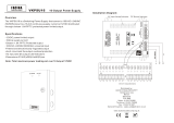
CAME NORD S.R.L.______COLOGNO M. (MI)
(+39) 02 26708293 (+39) 02 25490288
CAME SUD S.R.L. _________________NAPOLI
(+39) 081 752445 (+39) 081 7529109
CAME (AMERICA) L.L.C._________MIAMI (FL)
(+1) 305 5930227 (+1) 305 5939823
CAME AUTOMATISMOS S.A_________MADRID
(+34) 091 5285009 (+34) 091 4685442
CAME BELGIUM____________LESSINES
(+32) 068 333014 (+32) 068 338019
CAME CANCELLI AUTOMATICI S.P.A.
DOSSON DI CASIER (TREVISO)
(+39) 0422 4940 (+39) 0422 4941
CAME FRANCE S.A.___NANTERRE CEDEX (PARIS)
(+33) 01 46130505 (+33) 01 46130500
CAME GMBH____KORNTAL BEI (STUTTGART)
(+49) 071 5037830 (+49) 071 50378383
CAME GMBH________SEEFELD BEI (BERLIN)
(+49) 03 33988390 (+49) 03 339885508
CAME PL SP.ZO.O_________WARSZAWA
(+48) 022 8365076 (+48) 022 8369920
CAME UNITED KINGDOM LTD___NOTTINGHAM
(+44) 0115 9210430 (+44) 0115 9210431
A
SSISTENZA TECNICA
NUMERO VERDE
800 295830
W
EB
www.came.it
E-
MAIL
SISTEMA QUALITÀ
CERTIFICATO
DECLARATION DU FABRICANT
Aux termes de la disposition de l’Annexe II B de la Directive Machines 98/37/CE
Déclare sous sa responsabilité, que les produits suivants pour l’automation de
portails et portes de garage, ainsi dénommés:
ZL150N
... sont conformes aux conditions nécessaires et aux dispositions appropriées,
fi xées par les Directives suivantes et aux articles applicables des
Règlementations de référence indiqués ci-après.
--- DIRECTIVES ---
-> 98/37/CE - 98/79/CE DIRECTIVE MACHINES
-> 98/336/CEE - 92/31/CEE DIRECTIVE COMPATIBILITÉ
ELECTROMAGNÉTIQUE
-> 73/23/CEE - 93/68/CE DIRECTIVE BASSE TENSION
-> 89/106/CEE DIRECTIVE MATÉRIAUX DE CONSTRUCTION
--- RÈGLEMENTATIONS ---
EN 13241-1 • EN 12635 • EN 6100-6-2 • EN 12453 • EN 12978
EN 61000-6-3 • EN 12445 • EN 60335-1
AVIS IMPORTANT !
Il est interdit de mettre en service le/les produit/s, objet de cette déclaration,
avant de les incorporer à l’installation et/ou de terminer le montage de cette
dernière, conformément aux dispositions de la Directive Machines 98/37/CE.
L’administrateur délégué
Monsieur Andrea Menuzzo
Code de référence pour demander une copie conforme à l’original :
DDF B FR A001D
ERKLÄRUNG DES HERSTELLERS
Gemäß Anlage II B der Maschinenrichtlinie 98/37/EU
Bestätigt unter eigener Verantwortung, dass folgende automatische Antriebe für
Tore und Garagentore:
ZL150N
… den grundlegenden Anforderungen und entsprechenden Bestimmungen
der folgenden Richtlinien und der anzuwendenden Teilbestimmungen
der im folgenden aufgeführten Gesetzesvorschriften entsprechen.
--- RICHTLINIEN ---
-> 98/37/CE - 98/79/CE MASCHINENRICHTLINIE
-> 98/336/CEE - 92/31/CEE RICHTLINIE ÜBER ELEKTROMAGNETISCHE
VERTRÄGLICHKEIT
->73/23/CEE - 93/68/CE NIEDERSPANNUNGSRICHTLINIE
-> 89/106/CEE RICHTLINIE FÜR BAUMATERIALIEN
--- NORMEN ---
EN 13241-1 • EN 12635 • EN 6100-6-2 • EN 12453 • EN 12978
EN 61000-6-3 • EN 12445 • EN 60335-1
WICHTIGE HINWEISE!
Es ist untersagt, das/die diese Erklärung betreffende/n Produkt/e vor
Fertigstellung und/oder Einbau gemäß den Bestimmungen der
Richtlinie 98/37/EU zu verwenden.
Der Geshaftfürer
Herr Andrea Menuzzo
Code zur Anforderung einer dem Original entsprechenden Kopie:
DDF B DE A001D
DE FR
CAME cancelli automatici s.p.a. Via Martiri della Libertà, 15 31030 Dosson di Casier TREVISO - ITALY • www.came.it • info@came.it
IT
DICHIARAZIONE DI CONFORMITÀ
Ai sensi dell’allegato II B della
Direttiva Macchine 98/37/CE
Dichiara sotto la propria responsabilità, che i
seguenti prodotti per l’automazione di cancelli e
porte da garage, così denominati:
ZL150N
sono conformi ai requisiti essenziali ed alle
disposizioni pertinenti, stabilite dalle seguenti
Direttive e alle parti applicabili delle Normative di
riferimento in seguito elencate:
--- DIRETTIVE ---
-> 98/37/CE - 98/79/CE DIRETTIVA MACCHINE
-> 98/336/CEE - 92/31/CEE DIRETTIVA
COMPATIBILITÀ ELETTROMAGNETICA
-> 73/23/CEE - 93/68/CE DIRETTIVA
BASSA TENSIONE
-> 89/106/CEE DIRETTIVA MATERIALI
DA COSTRUZIONE
--- NORMATIVE ---
EN 13241-1 • EN 12635 • EN 6100-6-2 • EN 12453 •
EN 12978 • EN 61000-6-3 • EN 12445 • EN 60335-1
AVVERTENZA IMPORTANTE!
È vietato mettere in servizio il/i prodotto/i oggetto
della presente dichiarazione, prima del
completamento e/o incorporamento, in totale
conformità alle disposizioni della
Direttiva Macchine 98/37/CE
L’amministratore delegato
Andrea Menuzzo
Codice di riferimento per richiedere una copia
conforme all’originale:
DDF B IT A001D
DECLARATION OF CONFORMITY
Pursuant to annex II B of the
Machinery Directive 98/37/EC
Is fully liable in declaring that the products for
automatic garage doors and gates listed below:
ZL150N
comply with the National Law related to the following
European Directives and to the applicable parts of
the following Standards:
— DIRECTIVES —
-> 98/37/CE - 98/79/CE MACHINERY DIRECTIVE
-> 98/336/CEE - 92/31/CEE ELECTROMAGNETIC
COMPATIBILITY DIRECTIVE
-> 73/23/CEE - 93/68/CE LOW VOLTAGE
DIRECTIVE
-> 89/106/CEE CONSTRUCTION PRODUCTS
DIRECTIVE
--- STANDARDS ---
EN 13241-1 • EN 12635 • EN 6100-6-2 • EN 12453 •
EN 12978 • EN 61000-6-3 • EN 12445 • EN 60335-1
IMPORTANT WARNING!
Do not use the equipment specifi ed here above,
before completing the full installation In full
compliance with the Machinery Directive 98/37/EC
The Managing Director
Mr. Andrea Menuzzo
Reference code to request a true
copy of the original:
DDF B EN A001D
DECLARACIÓN DE CONFORMIDAD
De conformidad con el anexo II B de la
Directiva de Máquinas 98/37/CE
Declara bajo su exclusiva responsabilidad, que los
siguientes productos para la automatización de
cancelas y puertas para garajes, denominados:
ZL150N
son de conformidad con los requisitos esenciales y
las disposiciones pertinentes, establecidos por las
siguientes Directivas y con las partes aplicables de
las Normativas de referencia que se indican a
continuación:
--- DIRECTIVAS ---
-> 98/37/CE - 98/79/CE DIRECTIVA DE MÁQUINAS
-> 98/336/CEE - 92/31/CEE DIRECTIVA
COMPATIBILIDAD ELECTROMAGNÉTICA
-> 73/23/CEE - 93/68/CE DIRECTIVA BAJA TENSIÓN
-> 89/106/CEE DIRECTIVA MATERIALES PARA LA
FABRICACIÓN
--- NORMATIVAS ---
EN 13241-1 • EN 12635 • EN 6100-6-2 • EN 12453 •
EN 12978 • EN 61000-6-3 • EN 12445 • EN 60335-1
ADVERTENCIA IMPORTANTE!
Está prohibido hacer funcionar el/los producto/s,
objeto de la presente declaración, antes del
completamiento y/o incorporación de los mismos
(en la instalación fi nal), de conformidad con la
Directiva de Máquinas 98/37/CE
El administrador delegado:
Sig. Andrea Menuzzo
Código de referencia para solicitar una copia de
conformidad con la copia original:
DDF B ES A001D
CAME cancelli automatici s.p.a. Via Martiri della Libertà, 15 31030 Dosson di Casier TREVISO - ITALY • www.came.it • inf[email protected]
EN ES
  • Page 1 1
  • Page 2 2
  • Page 3 3
  • Page 4 4
  • Page 5 5
  • Page 6 6
  • Page 7 7
  • Page 8 8
  • Page 9 9
  • Page 10 10
  • Page 11 11
  • Page 12 12
  • Page 13 13
  • Page 14 14
  • Page 15 15
  • Page 16 16
  • Page 17 17
  • Page 18 18
  • Page 19 19
  • Page 20 20

CAME Z Series Owner's manual

Type
Owner's manual
This manual is also suitable for

Ask a question and I''ll find the answer in the document

Finding information in a document is now easier with AI