Legrand RS232 to RF Interface Installation guide
- Category
- Networking
- Type
- Installation guide
This manual is also suitable for

REV DESCRIPTION INT: REV. DATE APPROVED
1 ECO# C01301 MJS 3/21/05 CG
2 ECO# C01394 MJS 6/10/05 CG
3 ECO# C02412 DR 10/3/07 CG
4 ECO# C02476 MJS
TITLE BOX PAGE ONLY.
DO NOT MAKE FILM • DO NOT PRINT
MATERIAL: White 16lb (60g/m sq), uncoated, prefer recycled stock
Ink: Black
Print Two Sides, 2 sheets 8.5” (Wide) x 11”
(High), stapled upper left corner
OR
Print Two Sides, 1 sheet 11” x 17”
folded to 8.5” x 11”
IF YOU HAVE ANY QUESTIONS REGARDING SPECIFICATIONS OR REQUIRE
ADDITIONAL FILE FORMATTING, PLEASE CONTACT Mary Jo Sowinski.
Phone: 408-486-7511
Email: maryjo.sowinski@wattstopper.com
All information in this drawing is the property of Watt Stopper/Legrand
and cannot be copied or used without the written approval of
Watt Stopper/Legrand.
Title:
MR232 Installation Instructions
SANTA CLARA, CALIFORNIA
DRAWN BY
PLM
MARCOM
ENGINEERING
QA
TITLE BOX PG
SOWINSKI
SCALE 1:1
Drawing #:
05135
Orig. Drawing Date: 17 MAR 05
Revision Date: 19 NOV 07
REV. #:
4
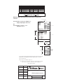
Inside Right PageInside Left Page
Back of Sheet
431.8mm
17”
215.9mm
8.5”
279.4mm
11”
4-page
booklet
fold
MRx###
Front PageBack Page
Center Fold
Front of Sheet
MRx###
279.4mm
11”
MRx###

I n sta l l a t i o n I n st r u c t i o n s
SPECIFICATIONS
UL and cUL Listed
MR232 Input Voltage .....................9-12VDC, 50mA minimum
AC-DC adaptor (provided)
Input ...............................................................120VAC, 60Hz
Output ..............................................................9VDC, 50mA
DESCRIPTION
The MR232 Network Controller provides the communication
interface between a Miro wireless lighting control system
and other RS232 compatible building controls. It acts as a
command and control station using an ASCII communication
protocol. With it, both humans and automation systems can
control virtually any Miro device on the wireless network.
The MR232 provides the ability to offer
interconnectivity with automation system and
building control integration providers.
Top Dog™ Wireless Communication
Miro wireless devices use radio signals to communicate
with each other to control lighting and other types of
electric loads in selected areas. These wireless devices use
the 900MHz band for high-speed control communication.
Using the “frequency-agile” Top Dog™ technology, these
wireless devices avoid interference with other 900MHz
devices, such as cordless phones and baby monitors.
OPERATION
The MR232 interfaces to an automation system
through an industry standard RS232 port.
In a typical installation the interface is bound to a
specific installation or house. This binding provides
direct access of the house presets as well as the 127
rooms and the 4095 possible groups on the network.
To query the wireless system and log the control points
(devices), connect the MR232 to a PC running a generic
terminal emulator such as Windows Hyper-TerminalTM
at 38.4Kbd. From this interface, the user can build an
installation list and use it to create a spreadsheet of all
the possible control points (devices) available on the
network. These control points can then be programmed
into the automation systems and provide a seamless
control environment between the two systems.
Power Fail Memory
After a power failure, all wireless devices
automatically return to the state that they were in
immediately prior to loss of power. All configuration
and scene control information is preserved.
Application Assistance
The MR232 Protocol Guide provides more information
about how to configure command sequences to pass
from a building automation control system through
the MR232 Network Controller and on to the Miro
wireless system. Instructions for installation, binding
operations, and use are included with the relevant
wireless devices. Application support information
and installation guides are available online.
Do not locate the MR232 close to any device that may
cause interference or behind large metal objects that can
block radio reception. Avoid fluorescent light fixtures, TV
sets, computers, refrigerators, microwave ovens, range
hoods, safes, etc.
INSTALLATION
1. Use an RS232 serial cable of the appropriate
length. If the one supplied is not appropriate, see
CONNECTIVITY for DB9 serial cable information.
2. Locate the MR232 within reach of the serial
cable connecting it to the building automation
system (max. 50 feet, unless an RS232 extension
device is used). Ideally, the MR232 should be in
a central location, taking into consideration both
the horizontal and vertical space in the building.
In a 2-story plus basement structure, a good
position may be on the first floor atop a cabinet.
3. Connect the DB9 serial cable to the
MR232 and control terminal.
4. Plug the external power supply into a
convenient 120 volt outlet, and connect the
power cord to the MR232’s power socket.
5. The status LED will light yellow, indicating
that the unit is ready for configuration.
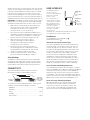
Set House ID
MR232
Network Controller
051HWZRUN&RQWUROOHU
6WDWXV/('
3RZHU6XSSO\
'%
56
3RUW
7R&RQWURO6\VWHP
566HULDO&DEOH

All Miro wireless devices installed in the same system must
acquire the same unique House ID before use. This process
is known as house binding. Each wireless device is bound
to all other wireless devices in the house. If you are not
familiar with the binding processes for the wireless devices
in your installation, please review the Installation Guide, or
individual installation instructions provided with the devices.
IMPORTANT: The MR232 can not be used to initiate a house
binding until it has acquired a house ID through a binding
initiated from another Miro wireless device in the system.
1. With all devices installed and energized, make sure
that every wireless device LED is yellow (amber).
If any LED is off, be sure the circuit breaker is
on and the device is correctly installed.
2. Go to any wireless device EXCEPT the MR232. Press
and hold the Up and the Down buttons simultaneously
until its LED flashes yellow (about 2 seconds). This
indicates that it has acquired a unique House ID.
3. Make sure that all other wireless device
LEDs are flashing green and the MR232 is
flashing yellow, indicating that they have
all acquired the same House ID.
4. Return to the device used in step 2, which is
still flashing yellow. Press and hold the Up and
the Down buttons simultaneously until the LED
changes to solid green (about 2 seconds).
5. All device LEDs in the House change to solid
green, indicating house binding is complete.
Other Bindings
The MR232 is a whole house device that is not bound to
any group or room. Other wireless devices in the system
should be bound to appropriate groups and rooms before
you attempt to control them from the Network Interface.
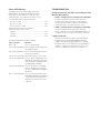
CONNECTIVITY
The illustration below shows the pin-outs from the
Miro Network Controller’s RS232 DB9 connector.
1
2
3
4
5
6789
RS232 Port
on MR232
5=Ground
3=RX
2=TX
1
2
3
4
5
6789
RS232 Port
on automation
system control
terminal
5=Ground
3=TX
2=RX
To communicate with the MR232 from the control system,
setup the terminal’s RS232 COM port as follows:
Baud Rate ..............................................................38.4Kbd
Data Bits ............................................................................ 8
Parity ........................................................................... None
Stop Bits ............................................................................ 1
Flow Control ............................................................... None
USER INTERFACE
The MR232 has two user
interfaces. The first
consists of two pushbuttons
and a multi-color LED
for device status.
The second interface is
through an ASCII terminal
connection over the RS232
port. Through this, ASCII
commands can be issued
and cause controlled
responses on the system.
The “HELP” command
lists the system
commands. The commands and operands are described
in the MR232 Protocol Guide, available online.
Pushbuttons
The pushbuttons are the Top button ( )
and the Bottom button ( ).
Initiate Version and Status Messages
Press either pushbutton to transmit an identification or
version message over the RS232 connection as well as
a status message over the wireless network. This can
be used to verify outgoing communications between the
serial interface and a terminal emulator. The message
includes the product name, part number, firmware
version, and current configuration. Regardless of the
configuration, it will also transmit a status message
on the wireless network with its MAC address so that it
can be identified like any other wireless network device.
(This message can be invoked over the ASCII interface
though the command line with the “VER” command.)
Learn Function and Binding Operations
Press both buttons simultaneously for about 2 seconds to
invoke the LEARN function. When un-configured the MR232
cannot be the first device to initiate a house binding (its
LED flashes red). However, after a house ID is assigned
to the MR232 - either by a house ID binding initiated from
another wireless device or with the “SETH” command - the
MR232 can be used to initiate future binding processes.
Reset to Factory Default/unconfigure
When both the buttons are simultaneously pressed
for a period of 10 seconds, the device will perform
a system reset and clear all memory contents. This
resets the device to an unbound, unconfigured state
with a House ID of zero (0) and Building ID of one (1).
Status LED
Green
Yellow (amber)
Red
Pushbuttons
Top
Bottom
Press both
simultaneously

Status LED Indicator
The MR232 uses color codes similar to all other
MIRO products. The LED can display one of three
colors: green, yellow (amber), or red. The color
can be constant, or can flash at one of three rates
to further distinguish reported conditions.
Once per second ........................................................... 1 Hz
Twice per second .........................................................2 Hz
Three times per second ...............................................3 Hz
To determine the flash rate, count the
number of flashes in 5 seconds:
5 flashes .......................................................................1 Hz
10 flashes......................................................................2 Hz
15 flashes......................................................................3 Hz
The MR232 LED indications are as follows:
Color Behavior Meaning
None Off Device is not powered.
Green On, not flashing Device is powered, has a house ID,
operating normally.
Green Flashing @ 2 Hz Device transmitted a message on
the wireless network.
Yellow On, not flashing Device does not have a house ID.
Yellow Flashing @ 2 Hz Device is part of a binding process.
Binding was started by some other
device with a matching house ID or
through GETID command.
Yellow Flashing @ 3 Hz Device is the master of a binding
process. Binding was started on
this device and must be stopped on
this device.
Red Flashing @ 2 Hz Device has encountered an error.
An invalid command or attempting
to transmit with an invalid house
ID (0x00). A non-zero house ID is
required.
TROUBLESHOOTING
During Set House ID, the LED is not flashing on some
Wireless Miro devices.
• If LED is solid green before initiating house ID binding:
The device already has another house ID. Reset
it to the factory default so that it can be bound to
the desired house ID. Resetting to factory defaults
is described in the “I need to start over” issue.
• If LED is solid yellow after initiating house ID binding:
The device may be out of range of the initiating
device. It may be necessary to add a MRR2 Repeater if
reception to a particular area of the house is blocked.
I need to start over.
You can reset any wireless device to factory default
settings by pressing and holding until the LED
changes to solid yellow (approximately 10 seconds).
During the process, the LED flashes yellow and when
complete, it changes to solid yellow. The device can
then be reconfigured, exactly like any new device.

WARRANTY INFORMATION
Manufacturer warranties its products to be free of
defects in materials and workmanship for a period
of five (5) years. There are no obligations or liabilities
on the part of manufacturer for consequential
damages arising out of, or in connection with, the
use or performance of this product or other indirect
damages with respect to loss of property, revenue or
profit, or cost of removal, installation or reinstallation.
Please
Recycle
05135r4 11/2007
Legrand Customers contact: Vantage Customers contact:
1061 South 800 East
Orem, UT 84097
Phone: 800.555.9891
www.vantagecontrols.com
FCC NOTICE
This equipment has been tested and found to comply with
the limits for a Class B digital device, pursuant to part 15
of the FCC Rules. These limits are designed to provide
reasonable protection against harmful interference in a
residential installation. This equipment generates, uses
and can radiate radio frequency energy and, if not installed
and used in accordance with the instructions, may cause
harmful interference to radio communications. However,
there is no guarantee that interference will not occur in
a particular installation. If this equipment does cause
harmful interference to radio or television reception,
which can be determined by turning the equipment
off and on, the user is encouraged to try to correct the
interference by one or more of the following measures:
• Reorientorrelocatethereceivingantenna.
• Increasetheseparationbetween
the equipment and receiver.
• Connecttheequipmentintoanoutletonacircuit
different from that to which the receiver is connected.
• Consultthedealeroranexperienced
radio/TV technician for help.
Caution: Any changes or modifications to this device
not explicitly approved by manufacturer could void
your authority to operate this equipment.
301 Fulling Mill Road Suite G
Middletown, PA 17057
Phone: 800.321.2343
www.legrand.us/onq
-
 1
1
-
 2
2
-
 3
3
-
 4
4
-
 5
5


Legrand RS232 to RF Interface Installation guide
- Category
- Networking
- Type
- Installation guide
- This manual is also suitable for
Ask a question and I''ll find the answer in the document
Finding information in a document is now easier with AI
Related papers
-
Legrand MR232 Wireless Miro RS232 Interface, Network Controller Installation guide
-
-
-
Legrand In-Wall RF Switch - DRD3 v2 Installation guide
-
-
-
-
-
-
Legrand MR232 Wireless Miro RS232 Interface, Network Controller Protocol and Command User guide