
Before Installing:
All installations should comply with National and local electrical
codes.
If you have any doubts concerning installation contact a qualified
licensed electrician.
1) TURN OFF POWER.
IMPORTANT: Before you start, NEVER attempt any work
without shutting off the electricity until the work is done.
a) Go to the main fuse, or circuit breaker, box in your
home. Place the main power switch in the “OFF” position.
b) Unscrew the fuse(s), or switch “OFF” the circuit breaker
switch(s), that control the power to the fixture or room
that you are working on.
c) Place the wall switch in the “OFF” position. If the fixture
to be replaced has a switch or pull chain, place those in
the “OFF” position.
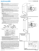
2) Attach mounting channel to outlet box.
3) Additional mounting slots are provided for mounting to the
wall surface if needed..
4) Never connect black or white power supply wires to the
ground screw.
5) Connect the black fixture wire to the black supply wire with
a suitable wire connector (not provided). Connect the white
Date Issued: 2/3/16 IS-45801LED-US
We’re here to help 866-558-5706
Hrs: M-F 9am to 5pm EST
This device complies with part 15 of the FCC Rules. Operation is subject to the following two conditions: (1) This device may not cause
harmful interference, and (2) this device must accept any interference received, including interference that may cause undesired operation.
Note: This equipment has been tested and found to comply with the limits for a Class B digital device, pursuant to part 15 of the FCC Rules.
These limits are designed to provide reasonable protection against harmful interference in a residential installation. This equipment gener-
ates, uses and can radiate radio frequency energy and, if not installed and used in accordance with the instructions, may cause harmful
interference to radio communications. However, there is no guarantee that interference will not occur in a particular installation. If this equip-
ment does cause harmful interference to radio or television reception, which can be determined by turning the equipment off and on, the
user is encouraged to try to correct the interference by one or more of the following measures:
• Reorient or relocate the receiving antenna.
• Increase the separation between the equipment and receiver.
• Connect the equipment into an outlet on a circuit different from that to which the receiver is connected.
• Consult the dealer or an experienced radio/TV technician for help.
fixture wire to the white supply wire with a suitable connector.
6) Plug the wires from the fixture front assembly into the plug
from the driver.
7) Secure the fixture front assembly to the mounting channel
by hooking the assembly onto mounting channel lower
edge. Rotate the assembly upwards until it is against the
wall. Secure on the top side with the 2 screws provided.
Models: 45836 LED/CP155680, 45801 LED/CP155210
45838 LED/CP15567, 45839 LED/CP155678
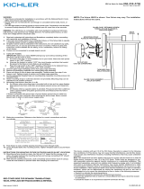
MOUNTING CHANNEL
CANAL DE MONTAGE
OUTLET BOX
CAJA DE SALIDA
SCREW
TORNILLO
DRIVER
CONTROLADOR
WIRE PLUGS
ENCHUFES DE
ALAMBRE
FIXTURE FRONT ASSEMBLY
ENSAMBLAJE DEL FRENTE
DEL ARTEFACTO
SCREW
TORNILLO
ADDITIONAL MOUNTING
SLOT
RANURA DE MONTAJE
ADICIONAL
SEE OTHER SIDE FOR SPANISH TRANSLATIONS.
VEA EL OTRO LADO DE TRADUCCIONES AL ESPAÑOL.
Page is loading ...

Before Installing:
All installations should comply with National and local electrical
codes.
If you have any doubts concerning installation contact a qualified
licensed electrician.
1) TURN OFF POWER.
IMPORTANT: Before you start, NEVER attempt any work
without shutting off the electricity until the work is done.
a) Go to the main fuse, or circuit breaker, box in your
home. Place the main power switch in the “OFF” position.
b) Unscrew the fuse(s), or switch “OFF” the circuit breaker
switch(s), that control the power to the fixture or room
that you are working on.
c) Place the wall switch in the “OFF” position. If the fixture
to be replaced has a switch or pull chain, place those in
the “OFF” position.
2) Attach mounting channel to outlet box.
3) Additional mounting slots are provided for mounting to the
wall surface if needed..
4) Never connect black or white power supply wires to the
ground screw.
5) Connect the black fixture wire to the black supply wire with
a suitable wire connector (not provided). Connect the white
Date Issued: 2/3/16 IS-45801LED-CB
We’re here to help 866-558-5706
Hrs: M-F 9am to 5pm EST
This device complies with part 15 of the FCC Rules. Operation is subject to the following two conditions: (1) This device may not cause
harmful interference, and (2) this device must accept any interference received, including interference that may cause undesired operation.
Note: This equipment has been tested and found to comply with the limits for a Class B digital device, pursuant to part 15 of the FCC Rules.
These limits are designed to provide reasonable protection against harmful interference in a residential installation. This equipment gener-
ates, uses and can radiate radio frequency energy and, if not installed and used in accordance with the instructions, may cause harmful
interference to radio communications. However, there is no guarantee that interference will not occur in a particular installation. If this equip-
ment does cause harmful interference to radio or television reception, which can be determined by turning the equipment off and on, the
user is encouraged to try to correct the interference by one or more of the following measures:
• Reorient or relocate the receiving antenna.
• Increase the separation between the equipment and receiver.
• Connect the equipment into an outlet on a circuit different from that to which the receiver is connected.
• Consult the dealer or an experienced radio/TV technician for help.
fixture wire to the white supply wire with a suitable connector.
6) Plug the wires from the fixture front assembly into the plug
from the driver.
7) Secure the fixture front assembly to the mounting channel
by hooking the assembly onto mounting channel lower
edge. Rotate the assembly upwards until it is against the
wall. Secure on the top side with the 2 screws provided.
Models: 45836 LED/CP155680, 45801 LED/CP155210
45838 LED/CP15567, 45839 LED/CP155678
INSTRUCTIONS
For Assembling and Installing Fixtures in Canada
Pour L’assemblage et L’installation Au Canada
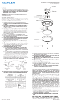
ADDITIONAL MOUNTING
SLOT
FENTE DE MONTAGE
SUPPLÉMENTAIRE
MOUNTING CHANNEL
CANAL DE MONTAGE
OUTLET BOX
BOÎTE À PRISES
SCREW
VIS
SCREW
VIS
FIXTURE FRONT ASSEMBLY
ASSEMBLAGE AVANT DU
LUMINAIRE
DRIVER
CONDUCTEUR
WIRE PLUGS
FICHES DE FILS
SEE OTHER SIDE FOR CANADIAN FRENCH TRANS-
LATIONS.
VOIR L’AUTRE CÔTÉ POUR LES CANADIENS TRA-
DUCTIONS EN FRANÇAIS.
Page is loading ...
-
 1
1
-
 2
2
-
 3
3
-
 4
4
Kichler Lighting 45838CHLED User manual
- Type
- User manual
- This manual is also suitable for
Ask a question and I''ll find the answer in the document
Finding information in a document is now easier with AI
in other languages
Related papers
-
 Kichler Lighting 49622BKTLED User manual
-
 Kichler Lighting 10763NILED User manual
-
 Kichler Lighting 11131AZTLED User manual
-
 Kichler Lighting 10790NILED User manual
-
 Kichler Lighting 49607AZTLED User manual
-
 Kichler Lighting 49626BKTLED User manual
-
 Kichler Lighting 49278AZTLED User manual
-
 Kichler Lighting 10766WHLED User manual
-
 Kichler Lighting 10755WHLED User manual
-
 Kichler Lighting 49625BKTLED User manual


