Page is loading ...

SAFETY WARNING
Only qualified personnel should install and service the equipment. The installation, starting up, and
servicing of heating, ventilating, and air-conditioning equipment can be hazardous and requires specific
knowledge and training. Improperly installed, adjusted or altered equipment by an unqualified person could
result in death or serious injury. When working on the equipment, observe all precautions in the literature
and on the tags, stickers, and labels that are attached to the equipment.
UniTrane™ Fan-Coil and Force-Flo™ Air Conditioners
200 to 1,200 cfm
April 2012 UNT-SVX07D-EN
Installation, Operation,
and Maintenance
Models FC and FF
“ZO” and later design sequence
Low vertical models FCKB and FCLB
“SO” and later design sequence
UNT-SVX07_-EN.book Page 1 Friday, April 27, 2012 9:40 AM

© 2012 Trane All rights reserved UNT-SVX07D-EN
Warnings, Cautions and Notices
Warnings, Cautions and Notices. Note that warnings,
cautions and notices appear at appropriate intervals
throughout this manual. Warnings are provide to alert
installing contractors to potential hazards that could result
in death or personal injury. Cautions are designed to alert
personnel to hazardous situations that could result in
personal injury, while notices indicate a situation that
could result in equipment or property-damage-only
accidents.
Your personal safety and the proper operation of this
machine depend upon the strict observance of these
precautions.
Read this manual thoroughly before operating or servicing
this unit.
Important
Environmental Concerns!
Scientific research has shown that certain man-made
chemicals can affect the earth’s naturally occurring
stratospheric ozone layer when released to the
atmosphere. In particular, several of the identified
chemicals that may affect the ozone layer are refrigerants
that contain Chlorine, Fluorine and Carbon (CFCs) and
those containing Hydrogen, Chlorine, Fluorine and
Carbon (HCFCs). Not all refrigerants containing these
compounds have the same potential impact to the
environment. Trane advocates the responsible handling of
all refrigerants-including industry replacements for CFCs
such as HCFCs and HFCs.
Responsible Refrigerant Practices!
Trane believes that responsible refrigerant practices are
important to the environment, our customers, and the air
conditioning industry. All technicians who handle
refrigerants must be certified. The Federal Clean Air Act
(Section 608) sets forth the requirements for handling,
reclaiming, recovering and recycling of certain
refrigerants and the equipment that is used in these
service procedures. In addition, some states or
municipalities may have additional requirements that
must also be adhered to for responsible management of
refrigerants. Know the applicable laws and follow them.
This product uses an electronic variable speed motor
control, which includes a line reactor to minimize power
line harmonic currents. It is recommended that good
wiring practices be followed to manage building electrical
power system harmonic voltages and currents to avoid
electrical system problems or other equipment
interaction.
ATTE NT ION: Warnings, Cautions and Notices appear at
appropriate sections throughout this literature. Read
these carefully:
WARNING
Indicates a potentially hazardous
situation which, if not avoided, could
result in death or serious injury.
CAUTIONs
Indicates a potentially hazardous
situation which, if not avoided, could
result in minor or moderate injury. It
could also be used to alert against
unsafe practices.
NOTICE:
Indicates a situation that could result in
equipment or property-damage only
WARNING
Proper Field Wiring and Grounding
Required!
All field wiring MUST be performed by qualified
personnel. Improperly installed and grounded field
wiring poses FIRE and ELECTROCUTION hazards. To
avoid these hazards, you MUST follow requirements for
field wiring installation and grounding as described in
NEC and your local/state electrical codes. Failure to
follow code could result in death or serious injury.
WARNING
Personal Protective Equipment (PPE)
Required!
Installing/servicing this unit could result in exposure to
electrical, mechanical and chemical hazards.
• Before installing/servicing this unit, technicians
MUST put on all Personal Protective Equipment (PPE)
recommended for the work being undertaken.
ALWAYS refer to appropriate MSDS sheets and OSHA
guidelines for proper PPE.
• When working with or around hazardous chemicals,
ALWAYS refer to the appropriate MSDS sheets and
OSHA guidelines for information on allowable
personal exposure levels, proper respiratory
protection and handling recommendations.
• If there is a risk of arc or flash, technicians MUST put
on all Personal Protective Equipment (PPE) in
accordance with NFPA 70E or other country-specific
requirements for arc flash protection, PRIOR to
servicing the unit.
Failure to follow recommendations could result in death
or serious injury.
UNT-SVX07_-EN.book Page 2 Friday, April 27, 2012 9:40 AM

Warnings, Cautions and Notices
UNT-SVX07D-EN 3
Revision History
The revision of this literature dated 27 Apr 2012 includes
information for Tracer™ UC400 controls.
Trademarks
Force-Flo, Rover, Tracer, Tracer Summit, Trane, the Trane
logo, and UniTrane are trademarks or registered
trademarks of Trane in the United States and other
countries. All trademarks referenced in this document are
the trademarks of their respective owners.
Echelon, LonTalk, and L
ONWORKS are registered
trademarks of Echelon Corporation; Energizer is a
registered trademark of Eveready Battery Company, Inc.;
Loctite is a registered trademark of Henkel Corporation.
UNT-SVX07_-EN.book Page 3 Friday, April 27, 2012 9:40 AM

4 UNT-SVX07D-EN
Table of Contents
Warnings, Cautions and Notices . . . . . . . . . . 2
Model Number Descriptions . . . . . . . . . . . . . . 6
General Information . . . . . . . . . . . . . . . . . . . . . 9
Pre-Installation . . . . . . . . . . . . . . . . . . . . . . . . . 10
Receiving and Handling . . . . . . . . . . . . . . 10
Jobsite Storage . . . . . . . . . . . . . . . . . . . . 10
Installation Preparation . . . . . . . . . . . . . . 10
Service Access . . . . . . . . . . . . . . . . . . . . . 11
Pre-Installation Checklist . . . . . . . . . . . . . 11
Dimensions and Weights . . . . . . . . . . . . . . . . 12
Available Models . . . . . . . . . . . . . . . . . . . 14
Factory-Installed Piping Packages . . . . . 15
Vertical Concealed, Model A . . . . . . . . . . 16
Vertical Cabinet, Model B . . . . . . . . . . . . 17
Horizontal Concealed, Model C . . . . . . . . 18
Horizontal Cabinet, Model D . . . . . . . . . . 19
Horizontal Recessed, Model E . . . . . . . . . 20
Vertical Wall Hung Cabinet, Model F (Force-
Flo Units Only) . . . . . . . . . . . . . . . . . . . . . 21
Vertical Recessed, Model H . . . . . . . . . . . 22
Vertical Slope Top, Model J . . . . . . . . . . 23
Low Vertical Concealed, Model K . . . . . . 24
Low Vertical Cabinet, Model L . . . . . . . . 25
Inverted Vertical Cabinet, Model M
(Force-Flo Units Only) . . . . . . . . . . . . . . . 26
Inverted Vertical Recessed, Model N (Force-
Flo Units Only) . . . . . . . . . . . . . . . . . . . . . 27
Compact Concealed, Model P . . . . . . . . . 28
Fan-Coil Coil Connections . . . . . . . . . . . . 29
Force-Flo Coil Connections . . . . . . . . . . . 30
Fresh Air Opening Locations . . . . . . . . . . 32
Wall Box . . . . . . . . . . . . . . . . . . . . . . . . . . 34
Projection Panel . . . . . . . . . . . . . . . . . . . . 35
Installation—Mechanical . . . . . . . . . . . . . . . . 36
Duct Connections . . . . . . . . . . . . . . . . . . . 36
Piping Considerations . . . . . . . . . . . . . . . 36
Installation—General . . . . . . . . . . . . . . . . . . . . 42
Installing the Unit . . . . . . . . . . . . . . . . . . . . . 42
Vertical Units . . . . . . . . . . . . . . . . . . . . . . 42
Horizontal Units . . . . . . . . . . . . . . . . . . . . .42
Cabinet Units . . . . . . . . . . . . . . . . . . . . . . .42
Recessed Units . . . . . . . . . . . . . . . . . . . . . .42
Installation Checklist . . . . . . . . . . . . . . . . . . .44
Installation—Controls . . . . . . . . . . . . . . . . . . . .45
General Information . . . . . . . . . . . . . . . . . . .45
Control Options (Including Factory-Installed)
. . . . . . . . . . . . . . . . . . . . . . . . . . . . . . . . . . .45
Installing Wall-Mounted Wired Sensors . .46
Location Considerations . . . . . . . . . . . . . .47
Location Considerations for Wireless zone
sensors . . . . . . . . . . . . . . . . . . . . . . . . . . . .47
Fan Mode Switch Installation . . . . . . . . . .47
Zone Sensor Installation . . . . . . . . . . . . . .47
Installation—Electrical . . . . . . . . . . . . . . . . . . .49
Unit Wiring Diagrams . . . . . . . . . . . . . . . .49
Supply Power Wiring . . . . . . . . . . . . . . . . .49
Electrical Grounding Restrictions . . . . . . .49
Wall-Mounted Control Interconnection Wir-
ing . . . . . . . . . . . . . . . . . . . . . . . . . . . . . . . .49
ECM Overview and Setup . . . . . . . . . . . . . . . .53
Overview . . . . . . . . . . . . . . . . . . . . . . . . . . . . .53
General Information . . . . . . . . . . . . . . . . . . .53
Trane BLDC Motor . . . . . . . . . . . . . . . . . . .53
ECM Engine Controller . . . . . . . . . . . . . . .54
Standard Adapter Board . . . . . . . . . . . . . .54
CSTI Adapter Board . . . . . . . . . . . . . . . . . .54
Installation and Initial Setup . . . . . . . . . . . .55
Installation and Initial Setup . . . . . . . . . . .55
Adjustment and Configuration of the Engine
Board . . . . . . . . . . . . . . . . . . . . . . . . . . . . . .57
Status Display . . . . . . . . . . . . . . . . . . . . . . .58
Initial Setup and Configuration . . . . . . . . .63
Configuration . . . . . . . . . . . . . . . . . . . . . . . . .63
Configuring the ECM Engine Controller . .63
Configuring the ECM Engine Board . . . . .68
Wired Controllers—Communication Wiring 73
Wiring Installation (ZN510 and ZN520) . . .73
Device Addressing . . . . . . . . . . . . . . . . . . .73
UNT-SVX07_-EN.book Page 4 Friday, April 27, 2012 9:40 AM

UNT-SVX07D-EN 5
Recommended Communication Wiring Prac-
tices . . . . . . . . . . . . . . . . . . . . . . . . . . . . . . 73
Wiring Installation (Tracer UC400) . . . . . . 73
Wiring Overview Outline . . . . . . . . . . . . . 74
General Instructions . . . . . . . . . . . . . . . . . 74
BACnet MS/TP Link . . . . . . . . . . . . . . . . . 74
Power Supply . . . . . . . . . . . . . . . . . . . . . . 75
Wireless Sensors . . . . . . . . . . . . . . . . . . . . . . . 77
Address Setting . . . . . . . . . . . . . . . . . . . . 77
Observing the Receiver for Readiness to As-
sociate . . . . . . . . . . . . . . . . . . . . . . . . . . . . 78
Associating the Sensor to the Receiver . 78
Testing Signal Strength and Battery Status
. . . . . . . . . . . . . . . . . . . . . . . . . . . . . . . . . . 78
Configuring the Wireless Display Sensor
(Model WDS only) . . . . . . . . . . . . . . . . . . 79
Sensor Operations . . . . . . . . . . . . . . . . . . 82
Wireless Sensor Specifications . . . . . . . . 85
Pre-Start . . . . . . . . . . . . . . . . . . . . . . . . . . . . . . . 87
Pre-Startup Checklist . . . . . . . . . . . . . . . . 87
Startup . . . . . . . . . . . . . . . . . . . . . . . . . . . . . . . . 88
Tracer ZN510 and ZN520 Unit Startup . . 88
Tracer UC400 Unit Startup . . . . . . . . . . . 88
General Information . . . . . . . . . . . . . . . . . 88
Fan Mode Switch Operation . . . . . . . . . . 89
Tracer ZN010 & ZN510 Operation . . . . . . 89
Tracer ZN520 Operation . . . . . . . . . . . . . 89
UC400 Controller Operation . . . . . . . . . . 89
Sequence of Operation: Tracer ZN010 and
ZN510
. . . . . . . . . . . . . . . . . . . . . . . . . . . . . . . 89
Binary Inputs (Tracer ZN010 and ZN510) 90
Binary Outputs (Tracer ZN010 and ZN510) 90
Tracer ZN520 Sequence of Operation . . . 92
Cooling Operation (Tracer ZN520) . . . . . 93
Fan Mode Operation (Tracer ZN520) . . . 94
UC400 Sequence of Operation . . . . . . . . . 99
Power-up Sequence (UC400) . . . . . . . . . 99
Random Start (UC400) . . . . . . . . . . . . . . . 99
Occupancy Modes (UC400) . . . . . . . . . . . 99
Timed Override Control (UC400) . . . . . 100
Zone Temperature Control (UC400) . . . 100
Discharge Air Tempering (UC400) . . . . .100
Heating or Cooling Mode (UC400) . . . . .100
Entering Water Temperature Sampling Func-
tion (UC400) . . . . . . . . . . . . . . . . . . . . . . .101
Fan Operation (UC400) . . . . . . . . . . . . . .101
Exhaust Control (UC400) . . . . . . . . . . . . .102
Valve Operation (UC400) . . . . . . . . . . . . .102
Modulating Outdoor/Return Air Damper
(UC400) . . . . . . . . . . . . . . . . . . . . . . . . . . .102
Two-position Control Of A Modulating Out-
door Air Damper (UC400) . . . . . . . . . . . .103
Electric Heat Operation (UC400) . . . . . . .103
Dehumidification Operation (UC400) . . .103
Peer-to-peer Communication (UC400) . .104
Unit Protection Strategies (UC400) . . . . .104
Maintenance . . . . . . . . . . . . . . . . . . . . . . . . . . .106
Maintenance Procedures . . . . . . . . . . . . .106
Replacing Motors . . . . . . . . . . . . . . . . . . .108
Periodic Maintenance Checklists . . . . . .110
Diagnostics . . . . . . . . . . . . . . . . . . . . . . . . . . . .112
Output Testing and Diagnostics (Tracer
ZN520)
. . . . . . . . . . . . . . . . . . . . . . . . . . . . . .112
Output Testing and Diagnostics (UC400) .115
Output Testing (UC400) . . . . . . . . . . . . . .115
Diagnostics (UC400) . . . . . . . . . . . . . . . .115
Troubleshooting (Wireless Controls) . . . .117
Troubleshooting (Tracer ZN520) . . . . . . .122
Troubleshooting (UC400) . . . . . . . . . . . .124
Troubleshooting (ECM) . . . . . . . . . . . . . .126
General Information (ECM) . . . . . . . . . . .126
Troubleshooting Information (ECM) . . .126
Replacing ECM Components . . . . . . . . . . . .129
Circuit Modules Replacement Notes/Work In-
structions . . . . . . . . . . . . . . . . . . . . . . . . .130
ECM Application Notes . . . . . . . . . . . . . . . . .132
Wiring Diagrams . . . . . . . . . . . . . . . . . . . . . . .133
UNT-SVX07_-EN.book Page 5 Friday, April 27, 2012 9:40 AM

6 UNT-SVX07D-EN
Model Number Descriptions
UniTrane Fan-Coil
Following is a complete description
of the fan-coil model number. Each
digit in the model number has a
corresponding code that identifies
specific unit options.
Note: Not all options are available
on all cabinet styles. Contact
your local Trane sales
representative for more
information.
Digits 1, 2 — Unit Type
FC = Fan-Coil
Digit 3 — Cabinet Type
A = Vertical Concealed
B = Vertical Cabinet
C = Horizontal Concealed
D = Horizontal Cabinet
E = Horizontal Recessed
H = Vertical Recessed
J = Vertical Cabinet Slope Top
P = Compact Concealed
Digit 4 — Development
Sequence “B”
Digits 5, 6, 7 — Unit Size
Digit 8 — Unit Voltage
Digit 9 — Piping System/
Placement
A = No piping, RH, No Auxiliary
Drain
Pan
B = No piping, LH, No Auxiliary
Drain
Pan
C = No piping, RH, with Auxiliary
Drain Pan
D = No piping, LH, with Auxiliary
Drain Pan
E = No piping, RH, No Auxiliary
Drain
Pan, Extended End Pocket
F = No piping, LH, No Auxiliary
Drain
Pan, Extended End Pocket
G = No piping, RH, with Auxiliary
Drain Pan, Extended End Pocket
H = No piping, LH, with Auxiliary
Drain Pan, Extended End Pocket
J = With piping package, RH
K = With piping package, LH
L = With piping package, RH,
Extended End Pocket
M = With piping package, LH,
Extended End Pocket
Digits 10, 11 — Design
Sequence
Digit 12 — Inlets
A = Front Toe Space
B = Front Bar Grille
C = Front Stamped Louver
D = Bottom Stamped Louver
E = Bottom Toe Space
F = Back Duct Collar
G= Back Open Return
H = Back Stamped Louver
K = Exposed fan (Model P only)
L = Bottom filter (Model P only)
Digit 13 — Fresh Air Damper
0=None
A = Manual, Bottom Opening
B = Manual, Back Opening
C = Manual, Top Opening
D = Auto, 2-Position, Bottom
Opening
E = Auto, 2-Position, Back Opening
F = Auto, 2-Position, Top Opening
G = Auto, Economizer, Bottom
Opening
H = Auto, Economizer, Back Opening
J = Auto, Economizer, Top Opening
K = No Damper, Bottom Opening
L = No Damper, Back Opening
M = No Damper, Top Opening
Digit 14 — Outlets
A = Front Duct Collar
B = Front Bar Grille
C = Front Stamped Louver
D = Front Quad Grille
G = Top Quad Grille
H = Top Bar Grille
J = Top Duct Collar
Digit 15 — Color
0 = No Paint (Concealed Units Only)
1 = Deluxe Beige
2=Soft Dove
3 = Cameo White
4 = Driftwood Grey
5 = Stone Grey
6=Rose Mauve
Digit 16 — Tamperproof Locks/
Leveling Feet
0=None
B = Keylock Access Door
C = Keylock Panel and Access Door
D = Leveling Feet
F = Keylock Access Door with
Leveling Feet
G = Keylock Panel and Access Door
with Leveling Feet
Digit 17 — Motor
A = Free Discharge ECM
B = High Static ECM
Digit 18 — Coil
A = 2-Row Cooling/Heating
1
B = 3-Row Cooling/Heating
1
C = 4-Row Cooling/Heating
1
D = 2-Row Cooling/1-Row Heating
E = 2-Row Cooling/2-Row Heating
F = 3-Row Cooling/1-Row Heating
G = 2-Row Cooling Only
H = 3-Row Cooling Only
J = 4-Row Cooling Only
K = 2-Row Cooling/Heating
1
with
Electric Heat
L = 3-Row Cooling/Heating
1
with
Electric Heat
M = 4-Row Cooling/Heating
1
with
Electric Heat
P = 2-Row Cooling/Heating
1
with
1-Row Heating
Q = 2-Row Cooling/Heating
1
with
2-Row Heating
R = 3-Row Cooling/Heating
1
with
1-Row Heating
X = 2-Row Cooling Only, Electric
Heat
Y = 3-Row Cooling Only, Electric
Heat
Z = 4-Row Cooling Only, Electric
Heat
Digit 19 — Drain Pan Material
3 = Polymer Drain Pan
4 = Stainless Steel Main Drain Pan
Digit 20 — Coil Air Vent
A = Automatic Air Vent
M= Manual Air Vent
020 040 080
030 060 100
120
1 = 115/60/1 4 = 230/60/1
2 = 208/60/1 9 = 220/50/1
3 = 277/60/1
UNT-SVX07_-EN.book Page 6 Friday, April 27, 2012 9:40 AM

Model Number Descriptions
UNT-SVX07D-EN 7
Digits 21, 22, 23 — Electric Heat
kW — ( ) = 208V Derate
000 = No Electric Heat
010 = 1.0 kW (0.75 kW)
015 = 1.5 kW (1.1 kW)
020 = 2.0 kW (1.5 kW)
025 = 2.5 kW (1.9 kW)
030 = 3.0 kW (2.3 kW)
040 = 4.0 kW (3.0 kW)
050 = 5.0 kW (3.8 kW)
060 = 6.0 kW (4.5 kW)
070 = 7.0 kW (5.3 kW)
080 = 8.0 kW (6.0 kW)
100 = 10.0 kW
Digit 24 — Reheat Coil
0=None
A = Steam Coil
B=Hot Water Coil
D = High Capacity Hot Water Coil
Digit 25 — Disconnect Switch
0=None
D = Disconnect Switch
Digit 26 — Filter
0=None
1 = 1” Throwaway Filter
2 = 1” Throwaway MERV 8 Filter
3 = 1” Throwaway, 1 Extra
4 = 1” Throwaway MERV 8, 1 Extra
5 = 1” Throwaway, 2 Extras
6 = 1” Throwaway MERV 8, 2 Extras
7 = 1” Throwaway, 3 Extras
8 = 1” Throwaway MERV 8, 3 Extras
A = 1” Throwaway MERV 13 Filter
B = 1” Throwaway MERV 13, 1 Extra
C = 1” Throwaway MERV 13, 2
Extras
D = 1” Throwaway MERV 13, 3
Extras
Digit 27 — Main Control Valve
0=None
A = 2-Way, 2-Position, NO (30 psig)
B = 3-Way, 2-Position, NO (28 psig)
C = 2-Way, 2-Position, NC (30 psig)
D = 3-Way, 2-Position, NC (20 psig)
E = 2-Way, 2-Position, NO (50 psig)
F = 3-Way, 2-Position, NO (28 psig)
G = 2-Way, 2-Position, NC (50 psig)
H = 3-Way, 2-Position, NC (28 psig)
J = 2-Way, Mod., 0.6 Cv (60 psig)
K = 3-Way, Mod., 0.6 Cv (60 psig)
L = 2-Way, Mod., 1.1 Cv (60 psig)
M = 3-Way, Mod., 1.1 Cv (60 psig)
N = 2-Way, Mod., 2.3 Cv (60 psig)
P = 3-Way, Mod., 2.7 Cv (60 psig)
Q = 2-Way, Mod., 3.3Cv (60 psig)
R = 3-Way, Mod., 3.8 Cv (60 psig)
X = Field-supplied, NO
Y = Field-supplied, NC
Z = Field-supplied 3-Wire
Modulating
1 = Field supplied analog valve
Digit 28 — Auxiliary Control
Valve
0=None
A = 2-Way, 2-Position, NO (30 psig)
B = 3-Way, 2-Position, NC (28 psig)
C = 2-Way, 2-Position, NC (30 psig)
D = 3-Way, 2-Position, NC (20 psig)
E = 2-Way, 2-Position, NO (50 psig)
F = 3-Way, 2-Position, NO (28 psig)
G = 2-Way, 2-Position, NC (50 psig)
H = 3-Way, 2-Position, NC (28 psig)
J = 2-Way, Mod., 0.6 Cv (60 psig)
K = 3-Way, Mod., 0.6 Cv (60 psig)
L = 2-Way, Mod., 1.1 Cv (60 psig)
M = 3-Way, Mod., 1.1 Cv (60 psig)
N = 2-Way, Mod., 2.3 Cv (60 psig)
P = 3-Way, Mod., 2.7 Cv (60 psig)
Q = 2-Way, Mod., 3.3Cv (60 psig)
R = 3-Way, Mod., 3.8 Cv (60 psig)
X = Field-supplied, NO
Y = Field-supplied, NC
Z = Field-supplied 3-Wire
Modulating
1 = Field supplied analog valve
Digit 29 — Piping Packages
0=None
A = Basic Ball Valve Supply and
Return
B = Basic Ball Valve Supply/Manual
Circuit Setter
C = Basic Ball Valve Supply and
Return with Auto Circuit Setter
D = Deluxe Ball Valve Supply and
Return
E = Deluxe Ball Valve Supply/Manual
Circuit Setter
F = Deluxe Ball Valve Supply and
Return with Auto Circuit Setter
Digit 30 — Control Type
A = Fan Mode Switch
E = Tracer ZN010
F = Tracer ZN510
G = Tracer ZN520
H = Customer Supplied Terminal
Interface (CSTI)
J = Tracer UC400, Single Zone VAV
Digit 31 — Control Option
D = Unit-Mounted Fan Mode Switch
K = Wall-Mounted Fan Mode Switch
V = Unit-Mounted Fan Speed Switch
w/Setpoint Dial Zone Sensor
W = Wall-Mounted Fan Speed Switch
w/Setpoint Dial Zone Sensor
X = Unit-Mounted Fan Speed Switch
w/Wall-Mounted Setpoint Dial
Zone Sensor
Y = Unit-Mounted Fan Speed Switch
& Wall-Mounted Setpoint Dial
w/Comm.
Z = Unit-Mounted Fan Speed Switch,
On/Cancel, Setpoint Dial
w/ Comm.
1 = Wall-Mounted On/Cancel
w/ Comm.
2 = Wall-Mounted Fan Speed Switch,
Setpoint Dial, On/Cancel
w/ Comm.
0 = Without Control Option
3 = Unit-Mounted Low Voltage Fan
Speed Switch (Off /Hi /Med /Low)
4 = Wall-Mounted Digital Zone
Sensor (OALMH, Setpoint,
On/Cancel, Comm Jack)
5 = Wall-Mounted Digital Zone
Sensor (On/Cancel, Comm Jack)
6 = Wireless Zone Sensor
7 = Wireless Display Sensor, Unit-
Mounted Receiver
Digit 32 — IAQ Options
0 = Without IAQ Options
1 = Dehumidification
4 = Dehumidification w/ Sensor
Digit 33 —FLA Motor Option
0 = Standard FLA ECM Mode
A = Reduced FLA ECM Mode
1
Designates coils provided with a changeover sensor.
UNT-SVX07_-EN.book Page 7 Friday, April 27, 2012 9:40 AM

Model Number Descriptions
8 UNT-SVX07D-EN
Digit 34
0 = None
Digit 35 — Control Function #3
0=None
2 = Condensate Overflow Detection
Digit 36 — Control Function #4
0=None
2 = Low Temperature Detection
Digits 37, 38 — Future Control
Functions
Digit 39 — Projection Panels
and Falsebacks
0=None
A = 5/8” Standard Recessed Panel
(Vertical Recessed Units Only)
B = 2” Projection Panel
C = 2.5” Projection Panel
D = 3” Projection Panel
E = 3.5” Projection Panel
F = 4” Projection Panel
G = 4.5” Projection Panel
H = 5” Projection Panel
J = 5.5” Projection Panel
K = 6” Projection Panel
L = 2”Falseback
M = 3” Falseback
N = 4” Falseback
P = 5” Falseback
Q = 6” Falseback
R = 7” Falseback
T = 8” Falseback
Digit 40 — Main Autoflow Gpm
Digit 41 — Auxiliary Autoflow
Gpm
Digit 42 — Subbases
0=None
A = 2” Subbase
B = 3” Subbase
C = 4” Subbase
D = 5” Subbase
E = 6” Subbase
F = 7” Subbase
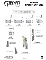
Digit 43 — Recessed Flange
0=None
A = Recessed Flange
Digit 44 — Wall Boxes
0=None
A = Anodized Wall Box
0=None H=3.5
A= 0.5 J=4.0
B = 0.75 K = 4.5
C=1.0 L=5.0
D= 1.5 M=6.0
E=2.0 N=7.0
F=2.5 P=8.0
G= 3.0
0=None H=3.5
A= 0.5 J=4.0
B = 0.75 K = 4.5
C=1.0 L=5.0
D= 1.5 M=6.0
E=2.0 N=7.0
F=2.5 P=8.0
G= 3.0
UNT-SVX07_-EN.book Page 8 Friday, April 27, 2012 9:40 AM

UNT-SVX07D-EN 9
General Information
UniTrane fan-coil and Force-Flo units are intended for
single zone applications. These units have load
capabilities of 200 to 1200 cfm. See Figure 1 for unit
components. Fan-coil units are available as two-pipe, with
or without electric heat (one hydronic circuit) or four-pipe
(two hydronic circuits). Force-Flo units feature two-pipe
hydronic, electric heat only, or steam only. Also, these
units feature a variety of factory mounted piping packages.
Units with the three-speed fan switch only, are available
with the switch mounted on the unit, or shipped
separately, to be mounted in the occupied space. The unit
mounted three-speed switch option can be ordered with a
low voltage (24 vols AC) transformer and three fan speed
relays. The three-speed switch option, which ships
separately, comes with a low voltage (24 volt AC)
transformer.
The Tracer ZN010, ZN510, ZN520, and UC400 controllers
are included inside the units control box assembly. These
controllers utilize analog signals from a unit-mounted
control device or from a control device mounted in the
occupied space.
The controls interface option, includes a 24 volt AC
transformer, and an interface terminal board. Controls
provided by an external source can be tied into the
interface terminal board utilizing the integrated terminal
block with 3mm screw connections.
Figure 1. UniTrane fan-coil unit components (vertical cabinet model is shown)
Factory-assembled, -installed,
and -tested piping package
with IAQ drain pan to collect
condensate.
Two-, three-, or
four-row coils.
Quiet operation.
Smaller unit footprint.
Factory-installed and
-tested controls.
Removable, noncorrosive,
positively-sloped drain pan
that’s easy to clean.
Easy-to-remove fan assembly.
16-gage steel construction.
Cleanable closed-cell
insulator (non-fiberglass).
Easy filter access
without front panel
removal.
Damper allows up to 100% fresh air.
Build in field service tool
with real language LED
Energy efficient
electronically
commutated motor (ECM)
UNT-SVX07_-EN.book Page 9 Friday, April 27, 2012 9:40 AM

10 UNT-SVX07D-EN
Pre-Installation
Receiving and Handling
Upon delivery, inspect all components for possible
shipping damage. See “Receiving Checklist” (below) for
detailed instructions. Trane recommends leaving units
and accessories in their shipping packages/skids for
protection and ease of handling until installation.
Shipping Package
UniTrane fan-coil and Force-Flo cabinet heaters ship in
individual cartons for handling and storage ease. Each
carton has tagging information such as the model number,
sales order number, serial number, unit size, piping
connections, and unit style to help properly locate the unit
in the floor plan. If specified, the unit will ship with tagging
designated by the customer.
Receiving Checklist
Complete the following checklist immediately after
receiving unit shipment to detect possible shipping
damage.
Jobsite Storage
This unit is intended for indoor use only. Store the unit
indoors to protect the unit from damage due to the
elements. If indoor storage is not possible, make the
following provisions for outdoor storage:
1. Place the unit(s) on a dry surface or raised off the
ground to assure adequate air circulation beneath unit
and to assure that no portion of the unit contacts
standing water at any time.
2. Cover the entire unit with a canvas tarp only. Do not
use clear, black or plastic tarps as they may cause
excessive moisture condensation and equipment
damage.
Installation Preparation
Before installing the unit, consider the following unit
location recommendations to ensure proper unit
operation.
1. Clearances: Allow adequate service and code
clearances as recommended in “Service Access” (the
next section). Position the unit and skid assembly in its
final location.
2. Structural support: Ensure
the structural support is
strong enough to adequately support the unit. The
installer is responsible for supply support rods for
installation of ceiling units.
3. Level: Verify the floor or foun
dation is level. Shim or
repair as necessary. To ensure proper unit operation,
install the unit level (zero tolerance) in both horizontal
axes. Failure to level the unit properly can result in
condensate management problems, such as standing
water inside the unit.
4. Condensate line & piping: Consider coil piping and
condensate drain
requirements. Verify condensate line
WARNING
Hazardous Voltage w/Capacitors!
Disconnect all electric power, including remote
disconnects and discharge all motor start/run
capacitors before servicing. Follow proper lockout/
tagout procedures to ensure the power cannot be
inadvertently energized. For variable frequency drives
or other energy storing components provided by Trane
or others, refer to the appropriate manufacturer’s
literature for allowable waiting periods for discharge of
capacitors. Verify with an appropriate voltmeter that all
capacitors have discharged. Failure to disconnect
power and discharge capacitors before servicing could
result in death or serious injury.
For additional information regarding the safe discharge of
capacitors, see PROD-SVB06A-EN
Inspect individual cartons before accepting. Check for
rattles, bent carton corners, or other visible indications
of shipping damage.
If a unit appears damaged, inspect it immediately
before accepting the shipment. Manually rotate the fan
wheel to ensure it turns freely. Make specific notations
concerning the damage on the freight bill. Do not
refuse delivery.
Inspect the unit for concealed damage before it is
stored and as soon as possible after delivery. Report
concealed damage to the freight line within the allotted
time after delivery. Check with the carrier for their
allotted time to submit a claim.
Do not move damaged material from the receiving
location. It is the receiver’s responsibility to provide
reasonable evidence that concealed damage did not
occur after delivery.
Do not continue unpacking the shipment if it appears
damaged. Retain all internal packing, cartons, and
crate. Take photos of damaged material.
Notify the carrier’s terminal of the damage
immediately by phone and mail. Request an immediate
joint inspection of the damage by the carrier and
consignee.
Notify your Trane representative of the damage and
arrange for repair. Have the carrier inspect the damage
before making any repairs to the unit.
Compare the electrical data on the unit nameplate with
the ordering and shipping information to verify the
correct unit is received.
UNT-SVX07_-EN.book Page 10 Friday, April 27, 2012 9:40 AM

Pre-Installation
UNT-SVX07D-EN 11
is continuously pitched 1 inch per 10 feet of condensate
line run to adequately drain condensate.
5. Wall & ceiling openings: Vertical recessed/concealed
u
nits require wall/ceiling openings. Refer to submittal
for specific dimensions before attempting to install.
Horizontal recessed/concealed units must meet the
requirements of the National Fire Protection
Association (NFPA) Standard 90A or 90B concerning
the use of concealed ceiling spaces as return air
plenums. Refer to the submittal for specific
dimensions of ceiling openings.
6. Exterior: Touch up painted panels if necessary. If
pa
nels need paint, sanding is not necessary. However,
clean the surface of any oil, grease, or dirt residue so
the paint will adhere. Purchase factory approved touch
up epoxy paint from your local Trane Service Parts
Center and apply.
Service Access
Service access is available from the front on vertical units
and from the bottom on horizontal units. Cabinet and
recessed units have removable front or bottom panels to
allow access into the unit. See Figure 2, p. 11 for
recommended service and operating clearances.
Units have either right or left hand piping. Reference
piping locations by facing the front of the unit (airflow
discharges from the front). The control panel is always on
the end opposite the piping.
The fan board assembly and main drain pan are easily
removable for cleaning. See “Maintenance,” p. 106 for
more details on servicing.
Pre-Installation Checklist
Complete the following checklist before beginning unit
installation.
Figure 2. Recommended service clearances
model B, vertical cabinet
model L, low vertical cabinet
12"
both sides
24"
3"
36"
model A, vertical concealed
model K, low vertical concealed
model H, vertical recessed
8.5"
both sides
12"
both sides
8.5"
both sides
28"
28"
model D, horizontal cabinet
model C, horizontal concealed
model E, horizontal recessed
24"
front discharge
Verify the unit size and tagging with the unit nameplate.
Make certain the floor or foundation is level, solid, and
sufficient to support the unit and accessory weights.
See “Dimensions and Weights,” p. 12. Level or repair
the floor before positioning the unit if necessary.
Allow minimum recommended clearances for routine
maintenance and service. Refer to unit submittals for
dimensions.
Allow one and one half fan diameters above the unit
before the discharge ductwork makes any turns.
UNT-SVX07_-EN.book Page 11 Friday, April 27, 2012 9:40 AM

12 UNT-SVX07D-EN
Dimensions and Weights
Table 1. Fan-coil component data
Unit Size 02 03 04 06 08 10 12
Coil Data
Face Area — ft
2
0.8 0.8 1.1 1.6 2.1 3.2 3.2
LxDxH — in.
2-Row 15 x 1.7 x 8 15 x 1.7 x 8 20 x 1.7 x 8 29.5 x 1.7 x 8 38 x 1.7 x 8 57 x 1.7 x 8 57 x 1.7 x 8
3-Row 15 x 2.6 x 8 15 x 2.6 x 8 20 x 2.6 x 8 29.5 x 2.6 x 8 38 x 2.6 x 8 57 x 2.6 x 8 57 x 2.6 x 8
4-Row 15 x 3.5 x 8 15 x 3.5 x 8 20 x 3.5 x 8 29.5 x 3.5 x 8 38 x 3.5 x 8 57 x 3.5 x 8 57 x 3.5 x 8
Volume — gal
1-Row (Heat) 0.06 0.06 0.08 0.11 0.14 0.21 0.21
2-Row 0.12 0.12 0.15 0.22 0.28 0.42 0.42
3-Row 0.18 0.18 0.23 0.33 0.42 0.62 0.62
4-Row 0.24 0.24 0.30 0.44 0.56 0.83 0.83
Fins/ft
2-Row 144 144 144 144 144 144 144
3-Row 144 144 144 144 144 144 144
4-Row 144 144 144 144 144 144 144
Reheat Coil Data (1-Row), Standard or High-Capacity
(a)
(a) Standard and high-capacity reheat coils share the same component data except that standard capacity reheat coils have 48 fins/ft (1.6 fins/cm) while
high-capacity reheat coils have 144 fins/ft (4.7 fins/cm).
Hot Water or Steam
Face Area — ft
2
0.6 0.6 0.8 1.2 1.6 2.4 2.4
L x D x H — in. 15 x 1.5 x 6 15 x 1.5 x 6 20 x 1.5 x 6 29.5 x 1.5 x 6 38 x 1.5 x 6 57 x 1.5 x 6 57 x 1.5 x 6
Volume — gal 0.12 0.12 0.15 0.22 0.28 0.42 0.42
Standard Capacity
(a)
Fins/ft 48 48 48 48 48 48 48
High-Capacity
(a)
Fins/ft 144 144 144 144 144 144 144
Fan/Motor Data
Fan Quantity 1112233
Size — Dia” x Width” 6.31 x 4 6.31 x 6.5 6.31 x 7.5 6.31 x 6.5 6.31 x 7.5 (1) 6.31 x 7.5 6.31 x 7.5
Size — Dia” x Width” (2) 6.31 x 6.5
Motor Quantity 1111122
Filter Data
1” TA and Pl. Media
Quantity 1111111
Size — in. 8-7/8 x 19-1/8 8-7/8 x 19-1/8 8-7/8 x 24-1/8 8-7/8 x 33-5/8 8-7/8 x 42-1/8 8-7/8 x 61-1/8 8-7/8 x 61-1/8
1” Fresh Air Filter (only on cabinet styles D, E, and H with bottom return and fresh air opening)
Quantity 1111111
Size — in 5-1/2 x 19-1/8 5-1/2 x 19-1/8 5-1/2 x 24-1/8 5-1/2 x 33-5/8 5-/2 x 42-1/8 5-1/2 x 61-1/8 5-1/2 x 61-1/8
UNT-SVX07_-EN.book Page 12 Friday, April 27, 2012 9:40 AM

Dimensions and Weights
UNT-SVX07D-EN 13
Table 2. Low vertical fan-coil component data
Unit Size 03 04 06
Coil Data
Face Area — ft
2
1.1 1.6 2.1
L x D x H — in.
2-Row 20 x 1.7 x 8 29.5 x 1.7 x 8 38 x 1.7 x 8
3-Row 20 x 2.6 x 8 29.5 x 2.6 x 8 38 x 2.6 x 8
Volume — gal
1-Row (Heat) 0.08 0.11 0.14
2-Row 0.15 0.22 0.28
3-Row 0.23 0.33 0.42
Fins/ft
2-Row 144 144 144
3-Row 144 144 144
Fan/Motor Data
Fan Quantity 1 1 1
Size — Dia”x Width” 5 x 23 5 x 32 5 x 41
Motor Quantity 1 1 1
Filter Data
1” (2.5 cm) TA
Quantity 1 1 1
Size — in. 8-7/8 x 24-1/8 8-7/8 x 33-5/8 8-7/8 x 42-1/8
UNT-SVX07_-EN.book Page 13 Friday, April 27, 2012 9:40 AM

Dimensions and Weights
14 UNT-SVX07D-EN
Available Models
Model A:
Vertical Concealed
Model B:
Vertical Short
Model C:
Horizontal Concealed
Model D:
Horizontal Cabinet
Model E:
Horizontal Recessed
Model F:
Wall Hung Cabinet
(Force-Flo units only)
Model L:
Low Vertical Concealed
Model K:
Low Vertical Cabinet
Model H:
Vertical Recessed
Model J:
Slope-Top Cabinet
Model M:
Inverted Vertical Cabinet
(Force-Flo units only)
Model N:
Inverted Vertical Recessed
(Force-Flo units only)
Model P:
Compact Concealed
UNT-SVX07_-EN.book Page 14 Friday, April 27, 2012 9:40 AM

Dimensions and Weights
UNT-SVX07D-EN 15
Factory-Installed Piping Packages
Note: This figure shows piping package components and
basic arrangement. It is not an accurate pictorial of
what factory-installed piping packages look like.
Auto Circuit Setter (C)
UNT-SVX07_-EN.book Page 15 Friday, April 27, 2012 9:40 AM

Dimensions and Weights
16 UNT-SVX07D-EN
Vertical Concealed, Model A
Vertical Concealed Unit
Unit Size 200-300 400 600 800 1000-1200
No. of Fans1122 3
No. of Motors1111 2
A 2’-8 11/16” 3’-1 11/16” 3’-11 3/16” 4’-7 11/16” 6’-2 11/16”
B 1’-9 5/16” 2’-2 5/16” 2’-11 13/16” 3’-8 5/16” 5’-3 5/16”
C 1’-10 13/16” 2’-3 13/16” 3’-1 5/16” 3’-9 13/16” 5’-4 13/16”
D 1’-5 5/16” 1’-10 5/16” 2’-7 13/16” 3’-4 5/16” 4’-11 5/16”
E 1’-7 5/16” 2’-0 5/16” 2’-9 13/16” 3’-6 5/16” 5’-1 5/16”
Notes:
1. Coil connections are always on the drain pan side and opposite the control box.
2. Coil connections are 5/8” O.D. sweat. See p. 29 and p. 30 for locations.
3. All duct collar dimensions are to the outside of the collar.
4. See p. 33 for dimensions for outside air openings.
UNT-SVX07_-EN.book Page 16 Friday, April 27, 2012 9:40 AM

Dimensions and Weights
UNT-SVX07D-EN 17
Vertical Cabinet, Model B
Vertical Cabinet Unit
Unit Size 200-300 400 600 800 1000-1200
No. of Fans1122 3
No. of Motors1111 2
A 2’-9 5/16” 3’-2 5/16” 3’-11 13/16” 4’-8 5/16” 6’-3 5/16”
B 1’-9 5/16” 2’-2 5/16” 2’-11 13/16” 3’-8 5/16” 5’-3 5/16”
C 7 5/8” 7 1/8” 8 7/8” 7 1/8” 7 5/8”
D 1’-16” 2’-0” 2’-6” 3’-6” 5’-0”
E 1’-7 5/16” 2’-0 5/16” 2’-9 13/16” 3’-6 5/16” 5’-1 5/16”
F 3’-5 5/16” 3’-10 5/16” 4’-7 13/16” 5’-4 5/16” 6’-11 5/16”
Notes:
1. Coil connections are always on the drain pan side and opposite the control box
and unit control.
2. Coil connections are 5/8” O.D. sweat. See p. 29 and p. 30 for locations.
3. See p. 33 for dimensions for outside air openings.
UNT-SVX07_-EN.book Page 17 Friday, April 27, 2012 9:40 AM

Dimensions and Weights
18 UNT-SVX07D-EN
Horizontal Concealed, Model C
Horizontal Concealed Unit Dimensions (in.) and Weights (lb)
Unit Size 200-300 400 600 800 1000-1200
No. of Fans1122 3
No. of Motors1111 2
A 2’-8 11/16” 3’-1 11/16” 3’-11 3/16” 4’-7 11/16” 6’-2 11/16”
B 1’-9 5/16” 2’-2 5/16” 2’-11 13/16” 3’-8 5/16” 5’-3 5/16”
C 1’-10 13/16” 2’-3 13/16” 3’-1 5/16” 3’-9 13/16” 5’-4 13/16”
D 1’-7 3/8” 2’-0 3/8” 2’-9 7/8” 3’-6 3/8” 5’-1 3/8”
E 1’-6 1/8” 1’-11 1/8” 2’-8 5/8” 3’-5 1/8” 5’-0 1/8”
F 1’-7 5/16” 2’-0 5/16” 2’-9 13/16” 3’-6 5/16” 5’-1 5/16”
Notes:
1. Coil connections are always on the drain pan side and opposite the control
box.
2. Coil connections are 5/8” O.D. sweat. See p. 29 and p. 30 for locations.
3. All duct collar dimensions are to the outside of the collar.
4. See p. 32 for dimensions for outside air openings.
UNT-SVX07_-EN.book Page 18 Friday, April 27, 2012 9:40 AM

Dimensions and Weights
UNT-SVX07D-EN 19
Horizontal Cabinet, Model D
Horizontal Cabinet Unit
Unit Size 200-300 400 600 800 1000-1200
No. of Fans1122 3
No. of Motors1111 2
A 2’-9 5/16” 3’-2 5/16” 3’-11 3/16” 4’-8 5/16” 6’-3 5/16”
B 1’-9 5/16” 2’-2 5/16” 2’-11 13/16” 3’-8 5/16” 5’-3 5/16”
C 7 5/8” 7 1/8” 8 7/8” 7 1/8” 7 5/8”
D 1’-6” 2’-0” 2’-6” 3’-6” 5’-0”
E 1’-5 1/4” 1’-10 1/4” 2’-7 3/4” 3’-4 1/4” 3’-4 1/4”
F 3’-5 1/4” 3’-10 5/16” 4’-7 3/16” 5’-4 5/16” 6’-11 5/16”
G 8-5/8” 8-1/8” 9-7/8” 8-1/8” 8-5/8”
H 1’-4” 1’-10” 2’-4” 3’-4” 4’-10”
J 1’-7 3/4” 1’-11 3/4” 2’-7 3/4” 3’-3 3/4” 4’-11 3/4”
Notes:
1. Coil connections are always on the drain pan side and opposite the control
box.
2. Coil connections are 5/8” O.D. sweat. See p. 29 and p. 30 for locations.
3. All duct collar dimensions are to the outside of the collar.
4. See p. 32 for dimensions for outside air openings.
UNT-SVX07_-EN.book Page 19 Friday, April 27, 2012 9:40 AM

Dimensions and Weights
20 UNT-SVX07D-EN
Horizontal Recessed, Model E
Horizontal Recessed Unit
Unit Size 200-300 400 600 800 1000-1200
No. of Fans1122 3
No. of Motors1111 2
A 2’-11 13/16” 3’-4 13/16” 4’-2 5/16” 4’-10 13/16” 6’-5 13/16”
B 1’-9 5/16” 2’-2 5/16” 2’-11 13/16” 3’-8 5/16” 5’-3 5/16”
C 1’-10 13/16” 2’-3 13/16” 3’-1 5/16” 3’-9 13/16” 5’-4 13/16”
D 1’-7 3/8” 2’-0 3/8” 2’-9 7/8” 3’-6 3/8” 5’-1 3/8”
E 1’-6 1/8” 1’-11 1/8” 2’-8 5/8” 3’-5 1/8” 5’-0 1/8”
F 2’-8 7/16” 3’-1 7/16” 3’-10 15/16” 4’-7 7/16” 6’-2 7/16”
G 2’-10 5/16” 3’-3 5/16” 4’-0 13/16” 4’-9 5/16” 6’-4 5/16”
H 1’-7 3/4” 1’-11 3/4” 2’-7 3/4” 3’-3 3/4” 4’-11 3/4”
Notes:
1. Coil connections are always on the drain pan side.
2. Coil connections are 5/8” O.D. sweat. See p. 29 and p. 30 for locations.
3. All duct collar dimensions are to the outside of the collar.
4. See p. 32 for dimensions for outside air openings.
UNT-SVX07_-EN.book Page 20 Friday, April 27, 2012 9:40 AM
/