

2 ie-wfs-Wx8xxPlus-01
© Copyright: COMET SYSTEM, s.r.o.
This manual is forbidden to copy and make changes of any nature without
the express consent of COMET SYSTEM, s.r.o. All rights reserved.
COMET SYSTEM, s.r.o. constantly developing and improving its products.
Therefore, it reserves the right to make technical changes to the device /
product without prior notice.
Contact the manufacturer of this device:
COMET SYSTEM, s.r.o.
Bezrucova 2901
756 61 Roznov pod Radhostem
Czech Republic
www.cometsystem.com

ie-wfs-Wx8xxPlus-01 3
Content
CONTENT .................................................................................................. 3
INTRODUCTION ........................................................................................ 4
SAFETY PRECAUTIONS AND PROHIBITED HANDLING........................ 5
INSTALLATION ......................................................................................... 6
Device Mounting ........................................................................... 6
Switching the device on ................................................................ 8
Device display ............................................................................... 8
Device usage and settings .......................................................... 10
Alarm functions ........................................................................... 11
MANUFACTURED MODELS ................................................................... 14
APPLICATION NOTES ............................................................................ 17
OPERATING AND MAINTENANCE RECOMMENDATIONS ................... 19
TECHNICAL PARAMETERS ................................................................... 21
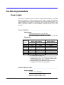
Power supply .............................................................................. 21
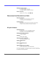
Measurement and transmission of data ...................................... 22
RF part of device ......................................................................... 22
Electromagnetic compatibility ...................................................... 23
Operating and storage conditions ............................................... 23
Mechanical properties ................................................................. 23
Transmitter Input Parameters ...................................................... 24
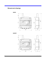
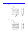
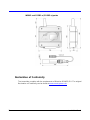
Dimensional drawings ................................................................. 28
Declaration of Conformity ............................................................ 30
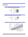
APPENDICES .......................................................................................... 31

4 ie-wfs-Wx8xxPlus-01
Introduction
The Sigfox network is used to transmit very short data messages and is
optimized for low power consumption. It operates in the unlicensed radio
band, which brings cheaper traffic, but also legislative restrictions -
messages can not be sent faster than with a 10 minute interval.
Ideal applications for transmitters working in the Sigfox network are those
where it is sufficient sending measured values with longer intervals (eg 1 h
or longer). Conversely, inappropriate applications are those where fast
system response (less than 10 minutes) is required.
The WX8xx series transmitters for the SIGFOX network are designed to
measure::
temperature
relative air humidity
relative air humidity
CO
2
concentracion in air
The transmitter performs a measurement every 1 minute. The measured
values are displayed on the LCD and are sent over an adjustable time
interval (10 min to 24 hour) via radio transmission in the Sigfox network to
the cloud data store. Through a common web browser, the cloud allows
you to view both actual and historical measured values. Transmitter setup
is done either by computer (locally, by communication cable) or remotely
via the cloud web interface.
For each measured variable, it is possible to set two alarm limits. The alarm
is signalled by the symbols on the LCD display and sending an
extraordinary radio message to the Sigfox network, where it is forwarded to
the end user by e-mail or SMS message. Extraordinary messages can also
be sent by the transmitter if the binary input state is changed (if equipped).
The device is powered by an internal Li battery whose lifetime is dependent
on the transmission range and operating temperature and ranges from 4
months to 7 years. The battery status information is on the display and in
each sent message.
The Wx8xx series transmitters are designed with increased resistance to
external influences (especially water protection), see technical data.
Operation without an internal battery (with external power only) is not
possible.

ie-wfs-Wx8xxPlus-01 5
Safety Precautions and Prohibited Handling
Read the following safety precautions carefully before using the appliance,
and keep it in mind during use!
The device includes a radio transmitter operating in the non-license
frequency band with the power specified in the Technical Parameters.
This band and performance are used in the countries of the European
Union. If you are in another location, make sure you can use the device
before turning it on for the first time.
Do not use the device in places where the use of mobile phones, such
as near sensitive medical devices, is restricted on the aircraft or in
places where blasting is taking place.
Observe the authorized storage and operating conditions listed in the
Technical Specifications. Take care not to subject the unit to
temperatures above 60 °C. Do not expose it to direct sunlight, including
solar radiation.
It is forbidden to use the transmitter in a hazardous environment,
especially in areas with the risk of explosion of flammable gases,
vapours and dust.
It is forbidden to operate the unit without a cover. After replacing the
battery or changing the instrument settings using the SP003 cable,
check the seal integrity and screw the device with the original screws.
Always follow the instructions in this manual carefully.
Do not expose the device to aggressive environments, chemicals or
mechanical shock. Use a soft cloth to clean. Do not use solvents or
other aggressive agents.
Do not attempt to service yourself. Any repairs may only be performed
by trained service personnel. If the device has unusual behaviour,
unscrew the device cap and remove the battery. Contact the distributor
from whom you purchased the device.
The device uses wireless communications and SIGFOX networks. For
this reason, the connection cannot always be guaranteed and under all
circumstances. Never rely exclusively on wireless devices for critical
communication purposes (rescue systems, security systems). Keep in
mind that redundancy is required for systems with high operational
reliability. More detailed information can be found e.g. in IEC 61508.
The device contains a special type of battery with other parameters than
conventional AA batteries. Use the type recommended by the
manufacturer in the Technical Parameters (Tadiran SL-2770/S, 3.6 V,
C size).
Replace the battery only with a person who knows the principles of safe
handling of lithium primary batteries. Apply the used batteries to
hazardous waste. In any case, do not throw them into a fire, expose
them to high temperatures, low air pressure and do not mechanically
damage them.
Only use the manufacturer's recommended accessories.

6 ie-wfs-Wx8xxPlus-01
Installation
Instalaci Installation, commissioning and maintenance must only be carried
out by a qualified person in accordance with applicable regulations and
standards.
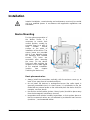
Device Mounting
For the optimum operation of
the Wx8xx Series, it is
necessary to ensure their
vertical position, usually by
screwing them on a wall or
other suitable vertical
surface at the place of
installation of the device. The
sensor boxes are provided
with 4.3 mm diameter holes
for fastening with suitable
screws. The holes are
accessible after removing
the cover. Fix the device
firmly only after verifying the
reception of the radio signal
at the required installation
location (see chapter
Switching the device on).
Basic placement rules:
always install the transmitters vertically, with the antenna cover up, at
least 10 cm away from all conductive objects
do not install the devices in underground areas (the radio signal is
generally unavailable here). In these cases, it is preferable to use the
model with an external probe on the cable and place the device itself, for
example, one floor above.
the devices and all cables (probes, binary inputs) should be place away
from electromagnetic interference sources
temperature and relative humidity transmitters, or their probes place so
that the measured values are not affected by accidental heat sources
(sunshine ...) and unwanted airflow
Antenna

ie-wfs-Wx8xxPlus-01 7
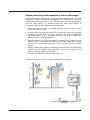
Optimal positioning of the transmitter in terms of radio range:
All materials absorb radio waves if they must pass through them. The most
significant in terms of radio wave propagation are metal objects, concrete,
reinforced concrete and walls. If you install the device at a greater distance
from the base station or in locations where the radio signal difficult to
penetrates, observe the following recommendations:
place the device as high as possible with the antenna better in open
space than near the wall
in rooms place the device at least 150 cm above the floor and if possible
not directly on the wall. For safety reasons, you do not exceed the
installation height of 2 m above the floor (the fall of the insufficiently
attached device can be dangerous).
place the device at a sufficient distance (at least 20 cm) away from all
obstacles that could cause attenuation of the radio waves and at least
20 cm from the neighbouring device in the case that you use multiple
devices
lead the cables of the external measuring probes and the external power
first down to the distance of at least 40 cm from the instrument. If the
cable is too long, install it by the figure.
do not use probes with a cable shorter than 1 m
Examples of optimal and less suitable positioning of the device:

8 ie-wfs-Wx8xxPlus-01
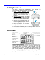
Switching the device on
The device is supplied with installed battery, but in off state. The
CONFIGURATION button is used to turn on the device:
models without waterproof cover
(W0841E, W6810, W8810) have a
CONFIGURTION button accessible via a
paper clip through the hole on the top of
the device
waterproof models (W0841 and W8861)
have a CONFIGURATION button under
the cover. Unscrew the four screws at the
corners of the box and remove the cover.
press the CONFIGURATION button (see
figures on the right) and release it as soon
as the LCD lights up (through the 1 s)
perform the installation and if necessary
set up the device too (see chapter Device
usage and settings)
finally, carefully screw on the cover. For waterproof models, making sure
that the gasket in the housing groove is correctly positioned.
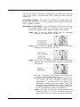
Device display
Radio Connection Indicator – Indicates the result of checking the bi-
directional radio connection with the cloud, which takes place once a day.
This connection allows the transmitter to be set remotely. If the radio
connection check is successful, the indicator will remain lit until the next
scan. When the transmitter is switched on, the indicator lights up after 24 h
(a good radio signal is required). The Radio connection indicator may light
up sooner if the user deliberately selects the transmitter setting mode by
pressing the CONFIGURATION button and it is correctly performed.

ie-wfs-Wx8xxPlus-01 9
If the remote setting in the device is disabled, the bi-directional connection
check to the cloud is not performed and the radio connection indicator
remains off.
Low Battery Symbol – Illuminates if the battery is already weak and
flashes when the battery is in critical condition (see the How to replace the
battery chapter for details)
Information on the display – they are displayed cyclically in three steps
(the images below contain only examples of the display, the
content of the display always depends on the specific model):
1. step (lasts 4 sec) the display shows data on measured
quantities on channels No.1 and No.2
2. step (lasts 4 sec) the display shows data on measured
quantities on channels No.3 and No.4
3. step (lasts 2 sec.) The display shows the service information
about the time of sending regular messages and external
power supply
P (Power) – information about presence of external power
supply is refreshed with interval of 1 min.
8x – shows how many times the regular message will be
sent before the new transmitter setup (if this
requirement is currently set in the cloud). The
information is reduced with each regular report sent.
Reading the new settings from the cloud occurs when
the display shows "1x 0 min". If the remote setting is in
the device disabled, this value is not displayed.
30 min – the time in minutes until a regular message with
measured values is sent (the information decreases
every minute from the currently set sending interval to
0).

10 ie-wfs-Wx8xxPlus-01
Device usage and settings
Factory setting
message sending interval of 10 minutes
alarms deactivated
remote setting enabled
for devices with pressure measurement set altitude 0 m (the device
displays absolute atmospheric pressure)
Working with the cloud _____________________________
Viewing measured values
Cloud is an internet storage of data. You need a PC with internet
connection and a web browser to work with. Navigate to the cloud address
you use and sign in to your account - if you use COMET Cloud by a
transmitter manufacturer, enter www.cometsystem.cloud and follow the
instructions in the COMET Cloud registration document that you received
with your device.
Each transmitter is identified by its unique address (device ID) in the Sigfox
network. The transmitter has an ID printed on the nameplate along with its
serial number. In the list of your device in the cloud, select the device with
the desired ID and and start viewing the measured values.
Checking the signal quality during device installation
The device in factory default setting will send the measured values every
10 minutes. Check in the cloud for messages to be received. Place the
device temporarily to the location where it will perform the measurements
and check the quality of the radio signal - in COMET Cloud click on the
correct device in the My Devices list and then select Installation. If you have
a problem with the signal, see the Problems with recieving radio messages
chapter.
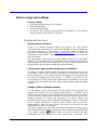
Change of device settings remotely
The transmitter can be set remotely from the cloud if the cloud you use
supports this feature. Run the remote setting feature - in COMET Cloud
click on the correct device in the My Devices list and then select Configure.
Set the desired sending interval (taking into account the fact that for short
sending intervals the battery life decreases), the limits, delays and
hysteresis of the alarms for the individual quantities (if used), or correction
of the altitude atmospheric pressure (only models with air pressure
measurement). Save the new setting. The device will accept this new
setting within 24 hours at the latest.
If you are running a new transmitter and want to speed up the setting, press
the CONFIGURATION button (the device must be switched on beforehand)
- the setting symbol (gears) lights up and the device will start
transmitting the new setting from the cloud within 10 minutes. The

ie-wfs-Wx8xxPlus-01 11
transmission itself will take up to 40 minutes depending on the range of the
new settings. The function can only be used once every 24 hours.
The location of the CONFIGURATION button varies depending on the
transmitter model. For details, see Switching the device on chapter.
Working with the COMET Vision SW ___________________
Change of device settings by connecting to a PC
The transmitter can be set directly from the PC using the SW COMET
Vision and Communication Cable SP003 (Optional accessory). Software
COMET Vision is downloadable on the web www.cometsystem.com, as
well as a manual for its installation and use.
Unscrew the device cover and connect it to the SP003 cable with the USB
port on the computer. Start the Comet Vision program and make a new
device setting. After you have saved the new settings, unplug the cable and
screw the device cover carefully. For waterproof devices, pay attention to
the correct seal position.
Warning - do not leave the communication cable SP003 connected to the
transmitter if the cable is not connected to the PC USB port at the same
time or if the PC is switched off! The battery consumption in these cases
increases and the battery is drained unnecessarily.
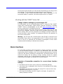
Alarm functions
The transmitter sends the measured values in regular messages, according
to the set sending interval. In addition, the transmitter can also send
extraordinary alarm messages when a new alarm is generated on a tracked
channel or the alarm in progress is extinguished. This feature allows you to
extend the battery life by setting a longer sending interval for regular
messages, and the user is informed about changes in the alarm status by
extraordinary messages according to the current situation.
Overview of transmitter properties for correct alarm function
settings
two alarms can be set for each channel (or measured quantity)
each alarm has an adjustable limit, direction of exceeding the limit, delay
and hysteresis
alarm delay can be set to 0-1-5-30 min except CO
2
channel, which has
adjustable delay only to 0 or 30 min
the longer the sending interval for regular messages, the greater the
battery capacity is saved.

12 ie-wfs-Wx8xxPlus-01
after a new alarm is triggered (or an alarm is ended), an extraordinary
alarm message is sent within 10 minutes at the latest. Temporary
interruption of the current alarm (max. 10 min) is not indicated. See the
examples in pics bellow.
the content of both regular and extraordinary alarm messages is
identical, both contain the measured values of all channels and current
alarm states on all channels
no even a short-term alarm (i.e. with a duration of 1 to 10 min) will not be
lost – the information will be sent no later than 10 min even if the alarm
is currently inactive. Device in alarm message sends the maximum value
measured during the alarm duration (or the minimum value, depending
on the current alarm threshold setting). See the examples in pics bellow.
due to the regulation of the unlicensed radio band, the device can not
send messages faster than every 10 minutes. If the device has fastest
sending interval (ie 10 minutes), no extraordinary alarm messages can
be sent
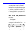
Examples of sent alarm messages triggered by changes in
the measured value (eg temperature)
Device configuration:
- sending interval: 30 min
- alarm for channel teparature: ON
- alarm will be activated if: value is greater than limit
- limit of alarm: any value
- delay of alarm: none
- hysteresis: 0 °C
After a new alarm is triggered, an extraordinary alarm message is sent
within 10 minutes at the latest. Temporary interruption of the current
alarm (max. 10 min) is not indicated. After ended of alarm, an
extraordinary alarm message is sent within 10 minutes at the latest.
(A) regular message sent in sending interval
(B) extraordinary message - start of alarm
(C) extraordinary message - end alarm

ie-wfs-Wx8xxPlus-01 13
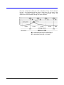
No even a short-term alarm (i.e. with a duration of 1 to 10 min) will not
be lost – the information will be sent no later than 10 min even if the
alarm is currently inactive. Device in alarm message sends the
maximum value measured during the alarm duration.
(A) regular message sent in sending interval
(B) extraordinary message - start of alarm
(C) extraordinary message - end alarm

14 ie-wfs-Wx8xxPlus-01
Manufactured models
COMET's Wx8xx transmitters differ in the type of measured quantities (temperature,
relative humidity, atmospheric pressure, CO
2
concentracion) and the location of the
sensors (compact design with internal sensors or external probes on the cable).
The enclosure covers electronic circuits, internal sensors, and a one or two batteries.
Depending on the type, the devices are fitted with connectors. The antenna is protected
by a cap.
Features overview of individual models:
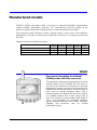
W0841
W0841E
W6810
W8810
W8861
possibility of external power supply
NO
YES
YES
YES
NO
slot for 2nd battery
NO
NO
NO
YES
YES
protection against dust and water
YES
NO
NO
NO
YES
W0841
Four inputs transmitter for external
Pt1000 probes with Elka connector
The transmitter measures the temperature from four
external probes of the Pt1000/E line (the probe is
not part of the instrument). Response to the jump
temperature change is usually much faster than the
models from the internal sensor. The transmitter is
often used to monitor locations where only a
measuring probe is installed and the device itself is
in a suitable location from a radio range point of
view. The maximum recommended probe length is
15 m. The transmitter has increased protection
against external influences (dust, water, humidity).
Supplied with connector caps for unused
temperature inputs.

ie-wfs-Wx8xxPlus-01 15
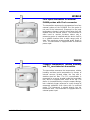
W0841E
Four inputs transmitter for external
Pt1000 probes with Cinch connector
The transmitter measures the temperature from four
external probes of the Pt1000/E line (the probe is
not part of the instrument). Response to the jump
temperature change is usually much faster than the
models from the internal sensor. The transmitter is
often used to monitor locations where only a
measuring probe is installed and the device itself is
in a suitable location from a radio range point of
view. The maximum recommended probe length is
15 m. The transmitter is equipped with an external
power input.
W6810
Compact temperature, relative humidity
and CO
2
concentracion transmitter
The transmitter measures the temperature, relative
humidity and dew point temperature by means of
internal sensors located under the cap with a
stainless-steel air filter. The CO
2
concentration is
measured by a sensor located inside the transmitter
box, which is equipped with vents at the top. The
device is characterized by a simple compact design,
but a relatively longer response to a step change of
measured quantities than those with an external
probe. The instrument is placed directly into the
measured area. The transmitter is equipped with an
external power input.

16 ie-wfs-Wx8xxPlus-01
W8810
Compact temperature and CO
2
concentracion transmitter
The transmitter measures the temperature and the
CO
2
concentration by a sensors located inside the
transmitter box, which is equipped with vents at the
top. The device is characterized by a simple
compact design, but a relatively longer response to
a step change of measured quantities than those
with an external probe. The instrument is placed
directly into the measured area. The transmitter is
equipped with an external power input and an slot
for 2nd battery, allowing for extended battery
operation.
W8861
Transmitter with input for external probe
measuring CO
2
concentration, with
internal temperature and atmospheric
pressure sensors
The transmitter measures temperature and
atmospheric pressure from built-in internal sensors
and CO
2
concentration from an external probe of
the CO2Rx/E series (not included). The transmitter
allows to measure higher CO
2
concentrations
(depending on the used probe) and with faster
response compared to devices with internal CO
2
sensor. Conversely, the response of the sensor to a
step change in temperature is relatively slow. The
CO2Rx/E probes provide calibrated readings and
are therefore interchangeable without interfering
with instrument settings. The maximum
recommended probe length is 4 m. The transmitter
has increased protection against external influences
(dust, water, humidity) and is equipped with an slot
for 2nd battery, allowing for extended battery
operation.

ie-wfs-Wx8xxPlus-01 17
Application notes
Operation of transmitter in various applications ___________
Prior to commissioning, it is first necessary to assess whether its use is
appropriate for the purpose, to determine its optimum setting and, if it is
part of a larger measuring system, to prepare a metrological and functional
control.
Inappropriate and risky applications: The transmitter is not intended for
applications where the failure of its operation could directly endanger the
lives and health of persons and animals or the function of other devices that
support life functions. For applications where failure or malfunction could
result in serious property damage, it is recommended that the system be
supplemented by a suitable independent signalling device that evaluates
this status and, in the event of a malfunction, prevents the damage (see
chapter Safety precautions and forbidden handling).
Device location: Follow the guidelines and procedures in this manual. If
possible, select the location for the device where it is minimally affected by
external environmental influences. If you perform measurements in fridges,
metal boxes, chambers, etc., place the device outside the exposed area
and insert external probe(-s) only.
Location of temperature sensors: Place them in places where there is
sufficient airflow and where you anticipate the most critical location
(according to application requirements). The probe must be sufficiently
inserted or otherwise sufficiently connected to the measured area to
prevent any influence of the measured values by the undesirable heat
supply on the wires. If you monitor the temperature in the air-conditioned
store, do not place the sensor in the air conditioner direct flow. E.g. in large
chamber refrigerators, the distribution of the temperature field can be very
inhomogeneous, deviations may reach up to 10 ° C. You will also find the
same deviations in the deep-freeze box (e.g. for blood freezing, etc.).
The location of the humidity sensors depends again on the application
requirements. It is very problematic to measure moisture in refrigerators
without moisture stabilization. Switching on / off cooling may cause
significant changes in humidity to a range of tens of percent, even if the
humidity mean value is correct. Humidity condensation on the walls of the
chambers is common.
Measurement of calculated humidity variables _____________
The instrument from the calculated humidity variables only provides the
dew point temperature. Further calculated humidity quantities can be
obtained at the level of further data processing in SW.

18 ie-wfs-Wx8xxPlus-01
Measurement of atmospheric pressure __________________
Models with atmospheric pressure measurement allow display on sea level
pressure readings. In order for the conversion to be correct, you must,
during device configure, enter the altitude at which the device will be
located. Altitude can be entered either directly, in the form of altitude data,
or indirectly, as an offset of absolute pressure. Offset of pressure is the
subtraction of pressure required (ie converted to sea level) minus absolute
pressure.
When converting pressure to sea level, the device takes into account the
temperature of the air column at the point of air pressure measurement.
Therefore, it is necessary to place the device with the altitude
correction in the outdoor. If this device is placed in a heated room, the
error in the recalculated pressure measurement will increase with the
temperature difference between the device and the outdoor air increases.
Problems with measurement accuracy __________________
Incorrect measured values of temperature and relative humidity are most
often caused by inadequate probe position or measurement methodology.
Some notes on this issue are listed in the chapter Operation of transmitter
in various applications.
Another group of problems are random peaks in the measured values.
Their most common cause is the source of electromagnetic interference
near the instrument or cables. In addition, it is also necessary to focus on
whether cable insulation is damaged in any place and that there are no
accidental connections of conductors with other metal parts.
Problems with recieving radio messages ________________
The causes of the problems can be many. If the receive of radio messages
does not work at all, you can try the following steps:
check whether the display is on and that the battery is weak
verify that the set transmission interval matches your expectations (on
the bottom line of the display, with of the 10 seconds interval always
for 2 seconds shows the number of minutes left until the message is
sent)
verify the coverage of the SIGFOX network for the transmitter
(https://www.sigfox.com/en/coverage or more detailed
http://coverage.simplecell.eu/)
transmitting from the interior of some buildings can be difficult, from
basements, as a rule, impossible. For testing purposes, therefore,
position the device as high as possible above the floor, put it on the
window, or even on the outside window sill (secure the device against
falling). If possible, test the location of the transmitter in other parts of
the building with respect to the world's sides.

ie-wfs-Wx8xxPlus-01 19
Operating and maintenance recommendations
Recommendations for metrological control _______________
Metrological verification is performed according to the requirements of your
own application in user-defined terms. In some cases, the calibration must
be performed by an independent state-accredited laboratory.
Recommendations for regular checks ___________________
The manufacturer recommends that the system in which the device is
incorporated be checked at regular intervals. The range and scope of the
tour depends on the application and the user's internal regulations. It is
recommended to perform these checks:
metrological verification
regular checks at intervals as specified by the user
evaluation of all the problems that have occurred since the last
inspection
visual inspection of the device, check the condition of connectors and
cables, and cover integrity
How to replace the battery ____________________________
The battery may only be replaced by a person who knows the principles of
safe handling of lithium primary batteries. Do not throw them into a fire, do
not expose them to high temperatures, and do not mechanically damage
them. Dispose the used batteries to hazardous waste.
If the low battery symbol starts to appear in the COMET cloud
received messages during operation, it is advisable to replace the
transmitter battery in the next 2-3 weeks. The empty battery symbol also
appears on the device display. A low battery indication may also occur if
the device is operated at extremely low temperatures even when the
battery is still usable (usually outdoors when in out-of-night messages).
During the day (after temperature rise), the indication disappears. In this
case, it is not necessary to change the battery.
A critically weak battery that can fail at any time is indicated by a blank
battery symbol in the COMET cloud and flashing the empty battery
symbol on the device display. Replace the battery as soon as possible.
Note: When operating the transmitter at very low temperatures, the flashing
of the blank battery symbol may not be on the sensor display visible.

20 ie-wfs-Wx8xxPlus-01
To replace the battery, unscrew the device cover, remove the old battery
and insert the new battery with the correct polarity. Refer to the battery
symbol + (plus pole) printed on the electronics board at the battery location:
For models with two battery slots: 1 or 2 batteries can be fitted. If you
decide to use two batteries, always use pieces of the same type and
manufacturer, from one supply, ie. of the same age. Always use new,
unused batteries. It is forbidden to mix batteries of different
manufacturers or to mix new batteries with used ones. If you use only
one battery, you can fit it into any slot.
Check the seal integrity in the housing (if equipped) and reinstall the cover.
Batteries can be purchased under their designation (SL2770/S) or, if
purchased from the manufacturer (COMET SYSTEM, s.r.o.), under order
code A4206.
Service Recommendations ____________________________
Technical support and service are provided by the distributor of this device.
Contact is provided in the warranty sheet supplied with the device.
WARNING - Improper handling or use of the device results in a loss of
warranty!
End of operation ___________________________________
Disconnect the measuring probes from the device. Return the device to the
manufacturer or dispose it as an electronic waste.
Page is loading ...
Page is loading ...
Page is loading ...
Page is loading ...
Page is loading ...
Page is loading ...
Page is loading ...
Page is loading ...
Page is loading ...
Page is loading ...
Page is loading ...
-
 1
1
-
 2
2
-
 3
3
-
 4
4
-
 5
5
-
 6
6
-
 7
7
-
 8
8
-
 9
9
-
 10
10
-
 11
11
-
 12
12
-
 13
13
-
 14
14
-
 15
15
-
 16
16
-
 17
17
-
 18
18
-
 19
19
-
 20
20
-
 21
21
-
 22
22
-
 23
23
-
 24
24
-
 25
25
-
 26
26
-
 27
27
-
 28
28
-
 29
29
-
 30
30
-
 31
31


Comet W0841 User manual
- Category
- Measuring, testing & control
- Type
- User manual
Ask a question and I''ll find the answer in the document
Finding information in a document is now easier with AI
Related papers
Other documents
-
RetroSound Hidden HPA1 Owner's manual
-
 Aranet ARANET4 Series User manual
-
 Sigfox Sigfox Access Station Micro SMBS-T4 Quick start guide
-
 Sigfox Sens’it 3.1 User manual
-
GMCiuk 800ppm User manual
-
Testo 480 User manual
-
PROTRONIX NL-ECO-CO2-230 User manual
-
 PROTRONIX NL-ECO-CO2-D User manual
-
 MerryIoT CO2 Operating instructions
-
Johnson Controls CD-W00-N0-2 Installation Instructions Manual


