Page is loading ...

Service Instructions
VA001-196-31 Rev. 2
October 2017
CBB Spring-Return Series Pneumatic Actuators
Disassembly and Reassembly


Service Instructions
VA001-196-31 Rev. 2
Table of Contents
October 2017
iTable of Contents
Table of Contents
Section 1: Introduction
1.1 General Service Information .......................................................................... 1
1.2 Denitions .................................................................................................... 2
1.3 General Safety Information ........................................................................... 2
1.4 Bettis Reference Materials ............................................................................. 3
1.5 Service Support Items ................................................................................... 3
1.6 Lubrication Requirements ............................................................................. 3
1.7 General Tool Information .............................................................................. 3
1.8 Actuator Weight ........................................................................................... 4
1.9 Actuator Storage ........................................................................................... 4
1.10 Actuator Installation ..................................................................................... 4
1.11 Actuator Startup ........................................................................................... 5
1.12 Actuator Operation ....................................................................................... 6
Section 2: Actuator Disassembly
2.1 General Disassembly ..................................................................................... 7
2.2 Spring Cylinder Disassembly .......................................................................... 8
2.3 Housing Disassembly .................................................................................... 9
Section 3: Actuator Reassembly
3.1 General Reassembly .................................................................................... 11
3.2 Housing Reassembly ................................................................................... 11
3.3 Spring Cylinder Reassembly ......................................................................... 14
Section 4: Actuator Testing
4.1 Actuator Testing ......................................................................................... 17
4.2 Return to Service ......................................................................................... 18
4.3 Pressure Requirement and Limitations for CBB-SR Actuators ....................... 18
Section 5: Troubleshooting
5.1 Fault Insertion ............................................................................................. 19
5.2 Operational Test .......................................................................................... 20
Section 6: Removal and Decommissioning
6.1 Removal and Decommissioning .................................................................. 21
Section 7: Document Revision ���������������������������������������������22
Appendix A: List of Tables ���������������������������������������������������23
Appendix B: List of Drawings ����������������������������������������������24

October 2017
Service Instructions
VA001-196-31 Rev. 2
1
Section 1: Introduction
Introduction
Section 1: Introduction
1�1 General Service Information
1�1�1 This service procedure is offered as a guide to enable general maintenance to be
performed on Bettis
TM
CBB-SR spring-return series actuators. The following is a list
of general CBB-SR models numbers.
Table 1� CBB-SR Model Numbers
MODEL (1) MODEL (1) MODEL (1)
CBB315-SR CBB315-SR-M3 CBB315-SR-M3HW
CBB415-SR CBB-415-SR-M3 CBB415-SR-M3HW
CBB420-SR CBB420-SR-M3 CBB420-SR-M3HW
CBB520-SR CBB520-SR-M3 CBB520-SR-M3HW
CBB525-SR CBB525-SR-M3 CBB525-SR-M3HW
CBB725-SR CBB725-SR-M3 CBB725-SR-M3HW
(1)Alsoincludesactuatormodelswith–10and–11asasufx
NOTE:
Whentheactuatormodelnumberhas“-S”asasufx,thentheactuatorisspecialandmay
have some differences that may not be included in this procedure.
1�1�2 Normalrecommendedserviceintervalforthisactuatorseriesisveyears.
NOTE:
Storage time is counted as part of the service interval.
1�1�3 This procedure is applicable with the understanding that all electrical power and
pneumatic pressure have been removed from the actuator.
1�1�4 Remove all piping and mounted accessories that will interfere with the module(s)
that are to be worked on.
1�1�5 This procedure should only be implemented by a technically competent technician
who should take care to observe good workmanship practices.
1�1�6 Numbers in parentheses ( ) indicate the bubble number (reference number) used
on the Bettis Assembly Drawing and Actuator Parts List.
1�1�7 Whenremovingsealsfromsealgrooves,useacommercialsealremovingtoolora
small screwdriver with sharp corners rounded off.
1�1�8 Use a non-hardening thread sealant on all pipe threads.
CAUTION: FOLLOW MANUFACTURER'S INSTRUCTIONS
Apply the thread sealant per the manufacturer’s instructions.
1�1�9 Bettis recommends that disassembly of the actuator should be done in a clean
area on a workbench.

October 2017
Service Instructions
VA001-196-31 Rev. 2
2
Section 1: Introduction
Introduction
1�2 Definitions
WARNING:
Ifnotobserved,userincursahighriskofseveredamagetoactuatorand/orfatalinjurytopersonnel.
CAUTION:
Ifnotobserved,usermayincurdamagetoactuatorand/orinjurytopersonnel.
NOTE:
Advisory and information comments provided to assist maintenance personnel to carry out
maintenance procedures.
NOTE:
Thisproductisonlyintendedforuseinlarge-scalexedinstallationsexcludedfromthe
scopeofDirective2011/65/EUontherestrictionoftheuseofcertainhazardoussubstances
in electrical and electronic equipment (RoHS 2).
M3:
Jackscreworjackscrewassembly
ES:
ExtendedStop(s)
1�3 General Safety Information
1�3�1 ProductssuppliedbyBettis,inits“asshipped”condition,areintrinsicallysafeifthe
instructions contained within this Service Instruction are strictly adhered to and
executedbywell-trained,equipped,preparedandcompetentpersonnel.
WARNING: FOLLOW WARNING AND CAUTION SIGNS
FortheprotectionofpersonnelworkingonBettisactuators,thisprocedureshouldbe
reviewed and implemented for safe disassembly and reassembly. Close attention should be
notedtotheWARNINGS,CAUTIONSandNOTEScontainedinthisprocedure.
WARNING: FOLLOW COMPANY SAFETY PROCEDURES
This procedure should not supersede or replace any customer’s plant safety or work
procedures.Ifaconictarisesbetweenthisprocedureandthecustomer’sproceduresthe
differencesshouldberesolvedinwritingbetweenanauthorizedcustomer'srepresentative
andanauthorizedBettisrepresentative.

October 2017
Service Instructions
VA001-196-31 Rev. 2
3
Section 1: Introduction
Introduction
1�4 Bettis Reference Materials
1�4�1 CBBXXX-SRXAssemblyDrawing,usepartnumber152230.
1�4�2 CBBXXX-SRX-M3HWAssemblyDrawing,usepartnumber152608.
1�5 Service Support Items
1�5�1 Bettis Service Kit
1�5�2 Commercial leak testing solution
1�5�3 Non-hardening thread sealant
1�6 Lubrication Requirements
1�6�1 The actuator should be relubricated at the beginning of each service interval using
the following recommended lubricants.
NOTE:
Lubricants other than those listed in steps 1.6.2 should not be used without prior written
approvalofBettisProductEngineering.Thelubricantitemnumberonsomeassembly
drawings is item (5) while the Bettis service kits lubricant item number is item number (500).
1�6�2 Alltemperatureservices(-50°Fto+350°F)/(-45.5°Cto176.6°C)useBettisESL-5
lubricant.ESL-5lubricantiscontainedintheBettisModuleServiceKitintubesand
thetubesaremarkedESL-4,5and10lubricant.
1�7 General Tool Information
1�7�1 AllthreadsonCBBseriesactuatorsareinchuniedandNPT.
1�7�2 Alltools/hexagonsareAmericanStandardinch.Twoadjustablewrenches,Allen
wrenchset,smallstandardscrewdriverwithsharpedgesroundedoff,
medium-sizestandardscrewdriver,diagonalcuttingpliers,externalsnapring
pliers,atle,driveratchet/deepwellsocketsetandtorquewrench
(upto2,000inchpounds/226N-m).

October 2017
Service Instructions
VA001-196-31 Rev. 2
4
Section 1: Introduction
Introduction
1�8 Actuator Weight
Table 2� Actuator Weight
Actuator
Model
Approximate
Weight (3)
Actuator
Model
Approximate
Weight (3)
CBB LB KG CBB LB KG
315-SR40 (1) 22 10.0 520-SR40 (1) 45 20.4
315-SR60 (1) 23 10.4 520-SR60 (1) 48 21.8
315-SR80 (1) 26 11.8 520-SR80 (1) 49 22.2
315-SR100 (1) 25 11.4 520-SR100 (1) 53 24.0
415-SR40 (1) 27 12.2 525-SR40 (2) 62 28.1
415-SR60 (1) 29 13.2 525-SR60 (2) 65 29.5
415-SR80 (1) 30 13.6 525-SR80 (2) 65 29.5
415-SR100 (1) 31 14.1 525-SR100 (2) 67 30.4
420-SR40 (1) 37 16.8 725-SR40 (2) 97 44.0
420-SR60 (1) 39 17.7 725-SR60 (2) 98 44.5
420-SR80 (1) 40 18.1 725-SR80 (2) 104 47.2
420-SR100 (1) 41 18.6 725-SR100 (2) 107 48.5
(1)Whenmodelhas-M3HWadd2.0pounds/0.9kilograms.
(2)Whenmodelhas-M3HWadd4.0pounds/1.8kilograms.
(3) Weight is for bare actuator without accessories or valve adaptation.
1�9 Actuator Storage
For applications where the actuator is not put into immediate service it is recommended
thattheactuatorbecycledwithregulatedclean/drypneumaticpressureatleastonceper
month.Indoorstorage,ifavailable,isrecommendedforallactuators.Careshouldbetaken
to plug all open ports on actuator and controls to keep out foreign particles and moisture.
Also,actuatorsshouldnotbestoredinanatmosphereharmfultoresilientseals.For
extendedstorage,contactthefactory.
1�10 Actuator Installation
1�10�1 Sincetherearemanyvalveandactuatorcombinations,itisnotpracticaltoinclude
detailed instructions for each type. Mountings are designed to be as simple as
possible to keep guess work out of installation.
1�10�2 Actuatorsareshippedfromthefactorywiththetravelstopsadjustedfor
approximatelyninety-degreerotation.Generallyitisnecessarytomakeslight
travelstopadjustmentsoncetheactuatorisinstalledonthevalve.Refertothe
valvemanufacturer'srecommendationsforspecicrequirements.Whenthevalve
hasinternalstops,theactuatorshouldbeadjustedatthesamepoints.
NOTE:
The actual "stopping" should be done by the actuator. If the valve does not have internal
stops,adjusttheactuatortothefullopenposition.Usingthisasareferencepoint,rotatethe
valveuntilit'sclosedandadjusttothevalvemanufacturer'sspecicationsfortotalrotation.

October 2017
Service Instructions
VA001-196-31 Rev. 2
5
Section 1: Introduction
Introduction
1�10�3 Goodinstrumentpracticesarealsorecommended.Clean/dryregulated
pneumatic pressure is essential for long service life and satisfactory operation.
It should be noted that new pneumatic lines often have scale and other debris in
them and these lines should be purged of all foreign material.
NOTE:
Scaleanddebriscandamagecontrolvalves,solenoids,seals,etc.
1�11 Actuator Startup
1�11�1 Prestart-up checks
a. Unithasbeenmountedonvalveproperly.Gearangemountingbolts,
stem key and setscrew(s) are installed and secured
b. No tubing damaged or accessories dislodged during shipping or
installation
c. Indicatedpositionconrmsvalveposition
d. All switching valves in normal operating position as per
Schematic/Instructions
1�11�2 Check Connections:
a. Pneumatic/hydrauliccomponentsconnectedasperschematicenclosed
or in service manual supplied
b. Pneumaticsupplyconnectedtoidentiedports
c. Electricalconnectionsterminalsaresecure
d. Wiring as per enclosed diagram or service manual supplied
1�11�3 Whenactuatorisrstputintoserviceitshouldbecycledwithregulated
pneumaticpressure.Thisisnecessarybecausethesealshavebeenstationary,
causingthemtotakea"set".Therefore,theactuatorshouldbeoperatedthrough
severalcycles,exercisingtheseals,resultinginaservice-readycondition.
1�11�4 The actuator speed of operation is determined by a number of factors including:
a. Power supply line length
b. Powersupplylinesize
c. Power supply line pressure
d. Controlvalveandttingoricesize
e. Torque requirements of the valve
f. Sizeoftheactuator
g. Setting of speed controls

October 2017
Service Instructions
VA001-196-31 Rev. 2
6
Section 1: Introduction
Introduction
1�11�5 Duetotheinteractionofthesevariablesitisdifculttospecifya"normal"
operating time. Faster operating times may be obtained by using one or more of
the following:
a. Larger supply lines
b. Larger control valve
c. Higher supply pressure*
d. Quickexhaustvalves
*Nottoexceedmaximumoperatingpressureofactuatororcontrolcomponents
1�11�6 Sloweroperatingtimesmaybeobtainedusingowcontrolvalvestometerthe
exhaust.Excessiveexhaustowmeteringmaycauseerraticoperation.Normally,
incoming supply should not be metered.
1�12 Actuator Operation
1�12�1 ControlledOperation:Controlledoperationisaccomplishedbypressurizingand/
ordepressurizingtheappropriatecylinderinlet(s)ofadouble-acting.
Do not exceed the pressures indicated on actuator nameplate�
1�12�2 ManualOperation:Allpressuremustbeventedorequalizedonbothsidesofthe
pneumatic piston prior to manual operation.

October 2017
Service Instructions
VA001-196-31 Rev. 2
7
Section 2: Actuator Disassembly
Actuator Disassembly
Section 2: Actuator Disassembly
2�1 General Disassembly
WARNING: DANGEROUS GAS AND/OR LIQUIDS
Itispossiblethattheactuatormaycontainadangerousgasand/orliquids.
Ensurethatallpropermeasureshavebeentakentopreventexposureorreleaseofthese
types of contaminants before commencing any work.
CAUTION: DO NOT EXCEED OPERATING PRESSURE
Pressureappliedtotheactuatorisnottoexceedthemaximumoperatingpressurerating
listed on the actuator name tag.
NOTE:
Before starting the general disassembly of the actuator it is a good practice to operate
actuator with the pressure used by the customer to operate the actuator during normal
operation.Notateandrecordanyabnormalsymptomssuchasjerkyorerraticoperation.
2�1�1 Removealloperatingpressurefromactuator,allowingthespringtostroke.The
spring will rotate the yoke to its fail position.
2�1�2 RecordthesettingsofstopscreworM3jackscrews(1-70)and(4-30)beforestop
screws are loosened or removed.
2�1�3 Recordthesettingsofstopscrew/ES/M3jackscrews(1-70)andstopscrew/ES
(4-30)before they are loosened or removed.
NOTE:
InplaceofstopscrewstheactuatormaybeequippedwithoneortwoES
(ES=ExtendedStops)oroneM3/M3HW(1-70)locatedonoutboardendofhousing(1-10).

October 2017
Service Instructions
VA001-196-31 Rev. 2
8
Section 2: Actuator Disassembly
Actuator Disassembly
2�2 Spring Cylinder Disassembly
NOTE:
Review Section 2 steps 2.1.1 through 2.1.2 before proceeding with cylinder disassembly.
CAUTION: SPRINGS ARE PRELOADED
The spring in CBB-Series spring-return actuators is preloaded.
WARNING: FOLLOW CORRECT DISASSEMBLY STEPS
Actuator must be disassembled in the following manner:
2�2�1 Removehexnut(1-80)asfollows:ForCBB315through725standardhousingstop
screworextendedstop(ES)usestep2.2.1.1.ForCBB315-SR-M3/M3HWthrough
CBB725-SR-M3/M3HWusestep2.2.1.2.
2�2�1�1 ForCBB315through725housingstopscreworextendedstopscrew(ES):
2�2�1�1�1 Loosenandremovehexnut(1-80)andwasher(2-35)fromstop
screw (1-70) located in housing (1-10).
2�2�1�1�2 Remove stop screw (1-70) located in housing (1-10).
2�2�1�2 ForCBB315/420/520/525/725-SR-M3orM3HW:
2�2�1�2�1 Remove retainer ring (12-30) and groove pin (12-20) from
optionalhexdrivehuborfromhandwheel(12-10).
2�2�1�2�2 Removeoptionalhexdrivehuborhandwheel(12-10)fromM3
jackscrew(1-70).
2�2�1�2�3 Loosenandremovehexnut(1-80)fromM3jackscrew(1-70).
NOTE:
ForCBB420,520,525,725-SR-M3orM3HWmodels:theM3jackscrew(1-70)cannotbe
removednow.TheM3jackscrewusedinthesemodelscanberemovedlaterinthis
procedure per step 2.3.7.
2�2�2 Loosenandremovehexnut(4-40)andwasher(4-90)fromendcapstopscrew
(4-30)orfromendcapextendedstop(4-30).
NOTE:
Extendedstoporendcapstopscrew(4-30)doesnotrequireremovalfromendcap(4-20)
unlessanewextendedstoporstopscrewisbeingreplaced.
2�2�3 Remove breather (30) from end cap (4-20).
2�2�4 FormodelswithBREATHER-10COLDTEMP,dothefollowing:
2�2�4�1 Removebreather(30-10),elbow(30-30)andhexnipple(30-20)from
end end cap (4-20).

October 2017
Service Instructions
VA001-196-31 Rev. 2
9
Section 2: Actuator Disassembly
Actuator Disassembly
2�2�5 Remove acorn nut (8-20) and gasket seal (5-50) from end cap (4-20).
2�2�6 Usearatchetandsocketontheweldednut,locatedonthehousingendofcenterbar
assembly (8-10). R-otate center bar assembly (8-10) counter-clockwise (CCW). This
will cause end cap (4-20) to gradually unscrew from center bar assembly (8-10).
NOTE:
The end cap (4-20) can be held in position by holding the end cap (4-20) with an
adjustablewrench.
2�2�7 Continue to rotate center bar assembly (8-10) counter-clockwise (CCW) until the
spring preload is eliminated. As preload is reduced it may be necessary to keep end
cap (4-20) from turning.
2�2�8 Afterthespringpreloadiseliminated,unscrewandremoveendcap(4-20)from
center bar assembly (8-10).
2�2�9 Remove spring (4-70) from within spring cylinder (4-10).
2�2�10 Hold torque shaft (1-30) and pull spring cylinder (4-10) away from housing (1-10);
slide spring cylinder over piston (4-50) and remove.
2�2�11 ForCBBXXX-SR-M3/M3HWmodels,dothefollowing:
2�2�11�1 Remove spacer (1-110) from center bar assembly (8-10).
2�2�12 ForCBBXXX-SRmodels,dothefollowing:
2�2�12�1 Remove spacer (4-25) from center bar assembly (8-10).
2�2�13 Pull piston (4-50) out of housing (1-10) and carefully slide piston off of center bar
assembly (8-10).
NOTE:
Piston (4-50) is an assembly made up of one roll pin and one yoke pin; do not attempt to
disassemble the piston assembly.
2�2�14 OnmodelsCBB415-SR,CBB520-SR,andCBB725-SR,removecylinderadapter(4-15).
2�3 Housing Disassembly
2�3�1 Remove center bar assembly (8-10) from housing (1-10).
2�3�2 Remove both retaining rings (1-60) from torque shaft (1-30). Remove washers
(1-65) from housing.
2�3�3 The following steps may be required before disassembly can continue.
2�3�3�1 If torque shaft (1-30) has any raised burrs or sharp edges they should
be removed.
NOTE:
Whenremovingburrsandsharpedges,removeaslittlemetalaspossible.
2�3�3�2 Ifthereisexcessivepaintbuild-upontorqueshaft(1-30)itshould
be removed.

October 2017
Service Instructions
VA001-196-31 Rev. 2
10
Section 2: Actuator Disassembly
Actuator Disassembly
2�3�4 Remove the torque shaft (1-30) by pushing it out one side of housing (1-10).
2�3�5 Remove yoke key (1-40) and yoke key spring (1-50) from torque shaft (1-30).
2�3�6 Remove yoke (1-20) from housing (1-10).
2�3�7 For actuator models CBB315-SR with a M3 or M3HW mounted in the outboard end
ofhousing(1-10),removeM3jackscrew(1-70)fromhousing(1-10).
NOTE:
TheM3jackscrew(1-70)willberemovedfromtheinsideofthehousing(1-10).
2�3�8 ForactuatormodelsCBB420,520,525and725withaM3orM3HWmountedin
the outboard end of housing (1-10) complete steps 2.3.8.1 and 2.3.8.2.
2�3�8�1 Remove retainer ring (2-40) from M3 adapter (1-90).
2�3�8�2 Remove M3 adapter (1-90) from housing (1-10).
NOTE:
TheM3adapterwillberemovedfromtheinsideofthehousing(1-10)withtheM3jackscrew.

October 2017
Service Instructions
VA001-196-31 Rev. 2
11
Section 3: Actuator Reassembly
Actuator Reassembly
Section 3: Actuator Reassembly
3�1 General Reassembly
CAUTION: CHECK SHELF LIFE OF SEALS
Onlynewsealsthatarestillwithinthesealsexpectantshelflifeshouldbeinstalledintothe
actuator being refurbished.
3�1�1 Remove and discard all old seals and gaskets.
3�1�2 All parts should be cleaned to remove all dirt and other foreign material prior
to inspection.
3�1�3 Allpartsshouldbethoroughlyinspectedforexcessivewear,stresscracking,
gallingandpitting.Attentionshouldbedirectedtothreads,sealingsurfaces
andareasthatwillbesubjectedtoslidingorrotatingmotion.Sealingsurfacesof
thecylinder,torqueshaftandcenterbarmustbefreeofdeepscratches,pitting,
corrosionandblisteringorakingcoating.OntheCBBmodels,therearetwo
O-ringsonthetorqueshaftandtwoextraO-ringsbeneaththewashersonthe
housing. These items MUST be replaced upon reassembly.
NOTE:
Coat the torque-shaft O-ring (2-25) with grease upon installation.
Thefollowingstepsusedtoreassemblethefollowingmodels:CBB315,420,520,525and
725. Use assembly drawing part numbers 152230 and 152608 for this section.
CAUTION: REPLACE WITH NEW PARTS
Actuatorpartsthatreectanyoftheabove-listedcharacteristicsmayneedreplacement
with new parts.
3�1�4 INSTALLATION LUBRICATION INSTRUCTIONS: Use the correct lubrication as
denedinSection1step1.6.
3�1�4�1 Beforeinstallation,coatallmovingpartswithlubricant.
3�1�4�2 Coatallsealswithlubricant,beforeinstallingintosealgrooves.
3�2 Housing Reassembly
NOTE:
Insection3.2wherethestepindicatesto"lubricate,coatorapplylubricant",uselubricant
asidentiedinSection1step1.6forlubricatingthepartbeinginstalled.
Review Section 3 steps 3.1.1 through 3.1.4 before proceeding with housing reassembly.
HousingM3jackscrew(1-70)installation:Usestep3.2.1forCBB315/415-SR-M3,andstep
3.2.2forCBB420/520/525/725-SR-M3includesM3HWmodels.

October 2017
Service Instructions
VA001-196-31 Rev. 2
12
Section 3: Actuator Reassembly
Actuator Reassembly
3�2�1 M3JACKSCREWINSTALLATIONFORCBB315/415-SR-M3
3�2�1�1 ApplyalightcoatingoflubricanttothethreadsofM3jackscrew(1-70).
NOTE:
M3jackscrew(1-70)willbeinstalledfrominsideofthehousing(1-10).
3�2�1�2 InsertandrotateM3jackscrew(1-70)intohousing(1-10).
NOTE:
RotatetheM3jackscrewintothehousinguntiltheinboardendoftheM3jackscrewisup
against the inside of housing (1-10).
3�2�1�3 InstallO-ringseal(2-30)ontoM3jackscrew(1-70)untilitisushwiththe
housing.
3�2�1�4 Installhexnut(1-80)ontoM3jackscrew(1-70)untilitishand-tight.
3�2�2 M3JACKSCREWINSTALLATIONFORCBB420/520/525/725-SR-M3.
3�2�2�1 Apply a coating of lubricant to outer diameter and inner diameter threads
of M3 adapter (1-90).
3�2�2�2 Coat O-ring seal (2-45) with lubricant and install into outer diameter seal
groove located in the M3 adapter (1-90).
3�2�2�3 ApplyalightcoatingoflubricanttothethreadsofM3jackscrew(1-70).
3�2�2�4 InstallandrotatetheM3jackscrew(1-70)intoM3adapter(1-90).
NOTE:
RotatetheM3jackscrewintotheadapteruntiltheinboardendofthejackscrewisup
against the adapter.
3�2�2�5 Install M3 adapter (1-90) into housing (1-10).
NOTE:
The M3 adapter will be installed from inside of the housing (1-10).
3�2�2�6 Install retainer ring (2-40) onto groove in M3 adapter (1-90).
3�2�2�7 InstallO-ringseal(2-30)ontoM3jackscrew(1-70).
NOTE:
MovetheO-ringseal(2-30)downtheM3jackscrewuntilitisnexttotheM3adapter.
3�2�2�8 Installhexnut(1-80)ontoM3jackscrew(1-70).

October 2017
Service Instructions
VA001-196-31 Rev. 2
13
Section 3: Actuator Reassembly
Actuator Reassembly
NOTE:
RotatethehexnutdowntheM3jackscrewuntilitisnexttotheM3adapter.
3�2�3 Apply a coating of lubricant to the torque shaft holes located on each side of
housing (1-10).
3�2�4 Coat torque shaft wiper seals (2-20) with lubricant and install in one of the grooves
located in the torque shaft bore of the housing (1-10).
NOTE:
The cup of torque shaft wiper seal will be installed facing down into the housing.
3�2�5 Coat yoke (1-20) with lubricant and install into housing (1-10). Apply a generous
amount of lubricant to the slots in the arms of yoke (1-20).
3�2�6 Inserttheyokekeyspring(1-50),withtheendspointingdown,intotheslotinthe
torque shaft (1-30) and place the yoke key (1-40) on top of the spring with the
tapered side outward.
WARNING: CHECK YOKE KEY INSTALLATION
Iftheyokekey(1-40)isinstalledincorrectlythehousingmaybedamagedwhenthenext
disassembly occurs. Refer to assembly drawing for correct yoke key spring and yoke
key orientation.
3�2�7 Hold the yoke key (1-40) down with your thumb; insert the torque shaft (1-30) by
gently rotating it into the housing (1-10) and yoke (1-20) on the opposite side of
the installed torque shaft wiper seal (2-20).
NOTE:
Torque Shaft should be installed with the key rotated 180 degrees opposite yoke key slot.
Whenthetorqueshaft(1-30)isushwiththehousing(1-10)pushthetorqueshaft(1-30)
throughuntiltheemptysealgrooveisexposed.Installtheothertorqueshaftwiperseal
(2-20) into the groove. The cup of the torque shaft wiper seal again needs to be installed
facing inward into the housing. Two new retaining rings (1-60) are contained in the Bettis
CBB Service Kits.
3�2�8 Installoneofthenewretainingrings(1-60)ontotheexposedendofthetorque
shaft,makingcertainitisproperlyseatedinthegrooveofthetorqueshaft(1-30).
Gently push and rotate the torque shaft (1-30) until the retaining ring (1-60) is
pressed against the housing (1-10). Install the other retaining ring (1-60) to the
other side of the torque shaft (1-30).
CAUTION: CHECK YOKE KEY ALIGNMENT
Rotate the torque shaft until the yoke key snaps into the yoke keyway.

October 2017
Service Instructions
VA001-196-31 Rev. 2
14
Section 3: Actuator Reassembly
Actuator Reassembly
3�2�9 Rotate the torque shaft (1-30) so that the arms of yoke (1-20) point outward.
3�2�10 Coat O-ring seal (5-20) with lubricant and install into inner diameter seal groove
located in the center bar hole of housing (1-10).
3�2�11 Coat entire length of center bar (8-10) with lubricant including the threads.
3�2�12 Insert center bar assembly (8-10) into the center hole of housing (1-10). Slide
centerbarassemblythroughhousinguntilcenterbarassemblynutisushagainst
the housing (1-10).
WARNING: DO NOT SCRATCH CENTER BAR ASSEMBLY
Care should be taken during installation of center bar assembly so as to not scratch it.
3�2�13 Recoat center bar assembly (8-10) with lubricant.
3�2�14 CoatoneO-ringseal(5-10)withlubricantandinstallontoouterdiameterange
located on housing adapter end of housing (1-10).
3�2�15 Foractuatorsequippedwithcylinderadapter(4-15),modelsCBB415-SR,CBB520-
SRandCBB725-SR,dosteps3.2.15.1and3.2.15.2.
3�2�15�1 Installcylinderadapter(4-15)ontohousingange,withthesteppedouter
diameter,ofcylinderadapter(4-15),facingawayfromhousing(1-10).
3�2�15�2 Install one O-ring seal (5-15) onto stepped diameter of cylinder adapter (4-15).
3�3 Spring Cylinder Reassembly
3�3�1 Coatpiston(4-50)outerdiametersealgroove,innerdiametersealgroove,headof
pistonandexposedendsofyokepinwithlubricant.
3�3�2 Coat O-ring seal (5-20) with lubricant and install in the internal seal groove in the
head of piston (4-50).
3�3�3 Coat seal (5-40) with lubricant and install into outer diameter seal groove of piston
(4-50).Thepistonsealwilltverylooselyintheouterdiametersealgroove.
3�3�4 Install bushing (4-80) between the two arms of yoke (1-20).
3�3�5 Withthepistonheadfacingawayfromhousing(1-10)andwithyokepinup,install
piston (4-50) onto center bar assembly (8-10).
3�3�6 Carefully slide piston (4-50) along center bar (8-10) until yoke pin engages the
yoke slots.
NOTE:
Whileholdingthecenterbarassemblyushagainstthehousing,pushpiston(4-50)into
housing (1-10) as far as the piston will go.
3�3�7 Apply a coating of lubricant to entire bore of spring cylinder (4-10).
3�3�8 Spring cylinder installation:
3�3�8�1 ForCBB415-SR,CBB520-SRandCBB725-SRmodelsinstallthelubricated
spring cylinder (4-10) over the piston and up against the O-ring seal on
thesteppeddiameterangeofcylinderadapter(4-15).

October 2017
Service Instructions
VA001-196-31 Rev. 2
15
Section 3: Actuator Reassembly
Actuator Reassembly
3�3�8�2 ForCBB315-SR,CBB420-SRandCBB525-SRmodelsinstallthelubricated
spring cylinder (4-10) over the piston and up against the O-ring seal on
theangeofhousing(1-10).
3�3�9 ForCBBXXX-SR-M3/M3HWmodels,dothefollowing:
3�3�9�1 Install spacer (1-110) onto center bar assembly (8-10).
3�3�10 ForCBBXXX-SRmodels,dothethefollowing:
3�3�10�1 Install spacer (4-25) onto center bar assembly (8-10).
3�3�11 Apply a coat of lubricant to the spring (4-70). Install the spring into the spring
cylinder by carefully sliding the spring into the open spring cylinder end until the
spring contacts the head of piston (4-50).
3�3�12 Endcapsealinstallation.
3�3�12�1 ForCBB415-SR,CBB520-SRandCBB725-SRmodelsinstallO-ringseal
(5-15) onto end cap (4-20).
3�3�12�2 ForCBB315-SR,CBB420-SRandCBB525-SRmodelsinstallO-ringseal
(5-10) onto end cap (4-20).
3�3�13 Ifremoved,installstopscrew/ES(4-30)intoendcap(4-20)andsetstopscrewto
theapproximatedsettingrecordedinSection2step2.1.2.
NOTE:
Whileholdingthecenterbarassemblyushagainstthehousing,pushpiston(4-50)into
the housing (1-10) as far as the piston will go.
3�3�14 Install end cap (4-20) onto center bar assembly (8-10) by rotating the end cap in a
clockwise direction.
3�3�15 Position the end cap (4-20) so that the breather port is at the bottom and the stop
screw/ES(4-30)isatthetop.
WARNING: DO NOT ALLOW END CAP TO ROTATE
Do not allow end cap (4-20) to rotate during center bar assembly tightening. The end cap
must maintain the position as described in step 3.3.14.
3�3�16 Keependcap(4-20)fromturningbyholdingendcapwithanadjustablewrench.
3�3�17 Usingaratchetandsocketonthecenterbarassemblynut,rotatecenterbar
assembly clockwise (CW). This will cause end cap (4-20) to gradually screw further
onto center bar assembly (8-10).
3�3�18 Continue to rotate center bar assembly (8-10) clockwise until spring (4-70) is
fullycompressed,springcylinderisseatedagainsttheangeofhousing(1-10)or
adapter(4-15),andendcap(4-20)isproperlyseatedinspringcylinder(4-10).

October 2017
Service Instructions
VA001-196-31 Rev. 2
16
Section 3: Actuator Reassembly
Actuator Reassembly
3�3�19 Tightencenterbarassembly(8-10)tothepropertorqueasspeciedinthe
following chart.
Table 3� Tightening Torque Center Bar
CBB Actuator
Model
Maximum Torque
Lbf-in� N-m
315-SR and 415-SR 55 75
420-SR and 520-SR 100 136
525-SR and 725-SR 130 176
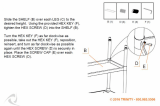
3�3�20 Placesealgasket(5-50)ontheexposedendofthecenterbarassembly(8-10).
3�3�21 Placeacornnut(8-20)ontheexposedoutboardendofcenterbarassembly(8-10)
and tighten securely.
3�3�22 Installthestopscrew/ES/M3jackscrew(1-70)forCBB315/415-SR-M3and
non-M3 model actuators as follows:
3�3�22�1 Installstopscrew/ES/M3jackscrew(1-70)intohousing(1-10)and
screw in until stop screw contacts the piston.
3�3�22�2 InstallO-ringseal(2-30)ontostopscrew/ES/M3jackscrew(1-70)until
itisushwiththehousing.
3�3�22�3 ForCBBXXX-SR-M3/M3HWmodels,installhexnut(1-80)ontostopscrew
(1-70) until it is hand-tight.
3�3�22�4 ForCBBXXX-SRmodles,installhexnut(4-40)andwasher(1-90)onto
stop screw (1-70) until hand-tight.
3�3�22�5 Installhexnut(1-80)ontostopscrew(1-70)untilitishand-tight.
3�3�23 InstallO-ringseal(5-30)ontothestopscrew/ES(4-30)untilitisushwiththeendcap.
3�3�24 Installnewwasher(4-90)ontothestopscrew/ES(4-30)untilitisclosetotheendcap.
3�3�25 Installhexnut(4-40)ontostopscrew/ES(4-30)untilitishandtight.
3�3�26 Adjuststopscrew/ES/M3jackscrew(1-70)andstopscrew/ES(4-30)backto
setting recorded in Section 2 step 2.1.2 under General Disassembly. Tighten both
stopscrewhexnuts(4-40)and(1-80)securely,whileholdingstopscrew(1-70)
and (4-30).
3�3�27 M3hexdrivehuborhandwheelinstallationasfollows:
3�3�27�1 Installhexdrivehub(12-10)orhandwheel(12-10)ontoM3jackscrew
(1-70) and align the “hole” of the drive hub with the “hole” located in the
M3jackscrew.
3�3�27�2 Installretainerring(12-30)andgroovepin(12-20)intothehexdrivehub
(12-10) or handwheel (12-10).

October 2017
Service Instructions
VA001-196-31 Rev. 2
17
Section 4: Actuator Testing
Actuator Testing
Section 4: Actuator Testing
4�1 Actuator Testing
4�1�1 Leak Test - General -Asmallamountofleakagemaybetolerated.Generally,a
small bubble which breaks about three seconds after starting to form is
considered acceptable.
4�1�2 Allareas,whereleakagetoatmospheremayoccur,aretobecheckedusinga
commercial leak testing solution.
WARNING: FOLLOW SERIAL TAG INFORMATION
Pressureisnottoexceedthemaximumoperatingpressureratinglistedontheserial
number tag (20).
4�1�3 All leak testing will use the customer normal operating pressure or the actuator
name tag normal operating pressure (NOP).
NOTE:
Whentestingtheactuator,useaproperadjustedregulatortoapplypressuretotheactuator.
4�1�4 Beforetestingforleaks,applyandreleasethepressurelistedinstep4.1.3tothe
housingsideofthepiston.Repeatthiscycleapproximatelyvetimes.
This will allow the new seals to seek their service condition.
4�1�5 Apply the pressure listed in step 4.1.3 to the housing side of the piston and allow
theactuatortostabilize.
4�1�6 Apply a leak-testing solution to the following areas:
4�1�6�1 SpringcylindertohousingjointonCBB315-SR,CBB420-SR,andCBB525-
SRorspringcylindertocylinderadaptertohousingjointsonCBB415-SR,
CBB520-SR,andCBB725-SRactuators
4�1�6�2 On the out board end of housing (1-10) at the center bar assembly nut.
Check the center bar to housing O-ring seal (5-20).
4�1�6�3 Housing stop screw O-ring seal (2-30).
4�1�6�4 Torque shaft (1-30) to housing (1-10) interface. Check rod wiper seals (2-20).
4�1�6�5 Endcap(4-20)porthole.Checkthepistontocylinderseal(5-40)and
piston to center bar seal (5-20).
4�1�6�6 Remove pressure from pressure inlet port in the housing (1-10).
4�1�7 Ifanactuatorwasdisassembledandrepairedasaresultofthisprocedure,
the above leakage test must be performed again.
4�1�8 Operational (Functional) Test: This test is used to verify proper function of the actuator.
NOTE:
This test is to be done off of the valve or when valve stem is not coupled to the actuator
torque shaft.
/