1
vacon • 4 Vacon 20 X - Simple operator panel
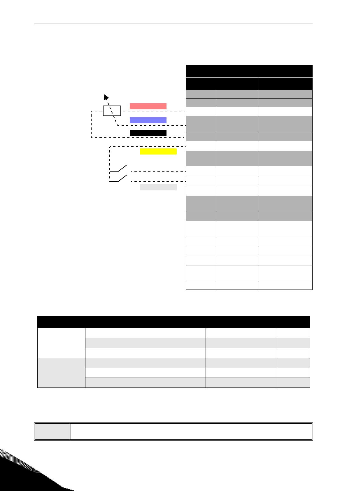
Table 2. Control I/O terminal signal connections to the simple operator panel.
Standard I/O terminals
Terminal Signal
A RS485_A Serial bus, negative
B RS485_B Serial bus, positive
1 +10 Vref Reference output
2
AI1+
Analogue input,
voltage or current
3
GND I/O signal ground
6
24Vout 24V aux. voltage
7
DIN COM
Digital inputs com-
mon
8
DI1 Digital input 1
9
DI2 Digital input 2
10
DI3 Digital input 3
4
AI2+
Analogue input,
voltage or current
5
GND I/O signal ground
13
DO1-
Digital output 1 com-
mon
14
DI4 Digital input 4
15
DI5 Digital input 5
16
DI6 Digital input 6
18
AO1+
Analogue signal
(+output)
20 DO1+ Digital output 1
Function Description Wire colors Terminal
Potentiomenter
10V reference output RED wire 1
AI1+ BLUE wire 2
AI1- BLACK wire 3
Switch selector
24V auxiliary voltage YELLOW wire 6
digital input DI1 WHITE wire 8
digital input DI2 GREY wire 9
Table 3. Simple operator panel connection description.
11
• Mount the plastic cover onto the drive with its screws and the HMI cap: the
installation process has been completed.
YELLOW WIRE
WHITE WIRE
GREY WIRE
RED WIRE
BLUE WIRE
BLACK WIRE


