
AW0719
AW0819
E
DB68-00322A (1)
S
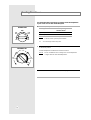
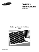
OWNER’S
INSTRUCTIONS
WINDOW-TYPE
ROOM AIR CONDITIONER
( Cool )

E-2
The following safety precautions must be taken when installing
and using your air conditioner.
Safety Precautions
1 The air conditioner must be plugged into its own specific power source, which must be
installed in compliance with national wiring, earthing and safety regulations.
Depending on national regulations and your specific installation, you may need to install:
◆ A circuit breaker
For further information on electrical requirements, contact a professional electrician.
This device must be installed according to the national electrical rules.
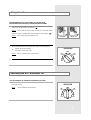
2 Make sure that the unit is correctly ventilated at all times;
do NOT place clothing or other materials over it.
4 Do NOT insert anything between the air outlet blades, as the inner fan may be damaged
and you may be hurt. Keep children away from the unit.
5 ALWAYS ensure that the power cable is in good condition.
Make sure that it is not walked on or damaged by items placed on or against it.
If the power cord is damaged in any way, it must be replaced by an approved
power cord available from the manufacturer or its service agent.
6 Do NOT attempt to repair the unit yourself. If it is damaged in any way, contact:
◆ An approved service center
◆ The outlet at which the air conditioner was purchased
7 Do NOT place any obstacles in front of the unit.
3 NEVER spill liquid of any kind into the unit.
Should this happen, unplug the unit and contact your installation specialist.

E-3
Contents
◆ PREPARING
YOUR AIR CONDITIONER
■ Safety Precautions ......................................................................................... 2
■ Air Conditioning Unit - Main Parts and Control Panel .................................... 4
■ Getting Started ............................................................................................... 5
◆ OPERATING YOUR AIR CONDITIONER
■ Cooling Your Room ........................................................................................ 6
■ Airing Your Room ........................................................................................... 7
■ Switching the Air Conditioner Off .................................................................... 7
■ Adjusting the Air Flow Direction Horizontally .................................................. 8
■ Adjusting the Air Flow Direction Vertically ...................................................... 8
◆ R
ECOMMENDATIONS FOR USE
■ Operating Recommendation ........................................................................... 9
■ Temperature and Humidity Ranges ................................................................ 9
■ Cleaning Your Air Conditioner ........................................................................ 10
■ Solving Common Problems ............................................................................ 11
■ Technical Specifications ................................................................................. 11
◆ I
NSTALLATION
....................................................................................................... 12

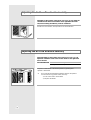
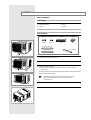
Air Conditioning Unit - Main Parts and Control Panel
E-4
OFF
LOW
COOL
LOW
FAN
HI
FAN
OPERATION
HI
COOL
THERMOSTAT
4
2
8
COOLEST
12
10
6
Outer air flow blades
(up/down orientation)
Air inlet (Inside)
Air filter
(The air filter is
located in inside.)
Ventilation lever
Air outlet
Air inlet (Outside)
Power plug
(
The type of the power plug
may differ according to the
type of local power supply.)
Temperature
control dial
Operating mode
selection dial
Inner air flow blades
(right/left orientation)
HOW TO OPEN THE OPERATING UNIT.
◆
Press the area marked “ ”on the door.
❄ The design and shape are subject to
change according to the model.

Getting Started
E-5
You have just purchased a window-type room air conditioner and it has been installed
by your installation specialist.
Your Owner’s Instructions contain much valuable information on using your air conditioner.
Please take the time to read them as they will help you take full advantage of the unit’s features.
The booklet is organized as follows.
◆ The illustration on page 4 shows the air conditioning unit;
it indicates the location and purpose of the main parts and controls on the unit.
◆ In the main part of the document, you will find a series of step-by-step
procedures for each function available.
The illustrations in the step-by-step procedures use four different symbols:
PRESS PUSH IMPORTANT NOTE
☛
➢

Select the operating mode and fan speed.
To cool your room with a... Set the operating mode
selection dial to...
High fan speed HI COOL
Low fan speed LOW COOL
Result: ◆
The air conditioner starts up in Cool mode.
◆
The fan starts up at the speed selected.
You can change modes at any time.
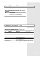
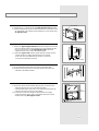
Cooling Your Room
E-6
You must select the Cool mode if you wish to lower the temperature
in your room. You can also set the fan speed.
1
2
To control the direction of the air flow, refer to page 8.3
To adjust the temperature, turn the temperature control dial
to the desirde position.
Possible temperatures: Between 64°F and 84°F inclusive.
Result: The air conditioner starts cooling if the room temperature
is higher than the selected temperature.
OFF
LOW
COOL
LOW
FAN
HI
FAN
HI
COOL
OPERATION
➢
4
2
8
12
10
6
COOLEST
THERMOSTAT
81˚F ~ 73˚F
73˚F
~ 64˚F
81˚F
~ 84˚F

OFF
LOW
COOL
LOW
FAN
HI
FAN
HI
COOL
OPERATION
OFF
LOW
COOL
LOW
FAN
HI
FAN
OPERATION
HI
COOL
Airing Your Room
Switching the Air Conditioner Off
E-7
To switch the unit off, simply set the operating mode selection dial
to the OFF position.
Result
: The air conditioner stops operating.
If the atmosphere in your room is stale, you can air it using
the Fan feature and if necessary, evacuate the stale air outside.
You can switch the air conditioner off whenever you want.
1
1
Set the operating mode selection dial to the HI FAN or LOW FAN position.
HI FAN : The fan turns rapidly.
LOW FAN : The fan turns slowly.
Result:
The air conditioner starts up in Fan mode.
2
To control the direction of the air flow, refer to page 8.
3
If you wish to evacuate stale air outside, push the ventilation lever on the front
of the unit to the right and the open position ( ).
Result:
The air inside the room circulates and stale air is evacuated outside.
Otherwise, push the ventilation lever to the left and the closed position ( ).
Result:
The air simply circulates inside the room.
➢

Adjusting the Air Flow Direction Horizontally
Adjusting the Air Flow Direction Vertically
E-8
Depending on the position of the unit in your room, you can adjust the
orientation of the inner air flow blades on the right-hand side of the
unit, thus increasing the efficiency of the air conditioner.
Hold the inner air flow blades, and adjust them to the desired direction.
Again depending on the position of the unit in your room, you can
adjust the orientation of the outer air flow blades on the right-hand
side of the unit.
RECOMMENDATION
When...
Cooling
Adjust the blades to face...
Upwards.
Adjust the air flow blades to the desired position, by pushing them
upwards or downwards.
If you orient the air flow blades downwards and the unit operates
in Cool mode for long periods of time, dew may:
◆
Form on the surface of the blades
◆
Drip from the blades
➢

If the air conditioner is used at... Then...
Higher temperature The automatic protection feature may be triggered
and the air conditioner stopped.
Lower temperature A water leakage or some other malfunction may happen
if the heat exchanger freezes.
Higher humidity levels Water may condense on and drip from the surface of the unit
if it is used for long periods.
The following table indicates the temperature and humidity ranges
within which the air conditioner can be used.
Mode Outdoor
Temperature
Indoor
Temperature
Indoor Humidity
Cooling 69.8°F to 109.4°F approx. 69.8°F to 89.6°F approx. 80% or less
Here is a recommendation that you should follow when using your
air conditioner.
Topic Recommendation
If a power failure occurs when the air conditioner is operating,
the unit is switched off. When the power returns,
the air conditioner starts up again automatically.
Power failure
Operating Recommendation
Temperature and Humidity Ranges
E-9

Cleaning Your Air Conditioner
E-10
If you... Then...
Will not be using the ◆ Set the fan going for a few hours
air conditioner for a to dry the inside of the air conditioner
long period of time thoroughly.
◆ Switch the air conditioner off and
unplug it from the wall socket.
◆ Clean the filter and outer surfaces.
Have not used the air Set the fan going for a few hours to
conditioner for a long dry the inside of the air conditioner
period of time thoroughly.
To get the best possible use out of your air conditioner,
you must clean it regularly to remove the dust on the air filter.
Before cleaning your air conditioner, ensure that it is
switched off and unplugged from the wall socket.
Hold the handle of the air filter, pull it slightly forward, and then pull it
out to the right side.
1
Remove all dust on the air filter with a vacuum cleaner or brush.
2
When you have finished, insert the air filter into the original position.
3
Clean the outer surfaces with a damp cloth and mild detergent
(do NOT use benzene, solvents or other chemicals).
Wipe them dry with a clean, soft cloth.
4
☛
➢

Solving Common Problems
E-11
EXPLANATION / SOLUTION
◆
Check that the circuit breaker used for the air conditioner
has not been triggered.
◆
Check that the power cable is plugged into a wall socket and the
socket is switched on, if necessary.
◆
Check that the correct operating mode has been selected
(cooling or airing).
◆
Check that the correct operating mode has been selected.
◆
The room temperature may be too low.
◆
Dust may be blocking the air filter;
refer to page 10 for cleaning instructions.
◆
Check that there is no obstacle blocking the air flow into or out of the unit.
PROBLEM
The air conditioner does not
operate at all
The air conditioner does not
cool
◆
Air the room.
Odours are permeated in the
room during air conditioning
Before contacting the after-sales service, perform the following simple checks.
They may save you the time and expense of an unnecessary call.
Technical Specifications
Model
Power Supply
AW0719
AW0819
115V~, 60Hz
Design and specifications are subject to change without notice.

Installation
Before installation, be sure to check the installation area
for the air conditioner, and installation method of the drain hose.
Checkpoints prior to installation
Check the cabinet and front grille of the unit for any harmful defects
such as scratches.
1
Be sure to check the power supply.
- Refer to the specifications on the label attached to the unit.
2
2
Installation Conditions
Electrical Requirements
For personal safety:
◆
This appliance must be properly grounded. See installation instructions.
◆
Do not, under any circumstances, cut or remove the third grounding
prong from the power cord.
◆
We recommend that you do not use an extension cord or an adapter
plug with this appliance.
◆
Do not change the plug on the power cord of this appliance.
◆
Follow national electrical codes or local codes and ordinances.
◆
If the electric supply provided does not meet the above specifications,
call a licensed electrician.
◆
Aluminum house wiring may pose special problems - consult a qualified
electrician.
◆
This unit requires a separate circuit serving only this appliance.
Window Requirements
◆
Standard double - hung window with actual opening width of 251/2" to 37".
The installation will need to be modified for windows other than
the standard double-hung type.
◆
Clear vertical opening of 143/4" minimum from bottom of sash to sill.
◆
Install the air conditioner in a window where there will be enough
clearance around the cabinet to allow ample circulation of air through
the unit.
115V
15 AMP circuit
"parallel" type
230V/208V
20 AMP circuit
"perpendicular" type
230V/208V
15 AMP circuit
"tandem" type
230V/208V
30 AMP circuit
"tandem" type
1
All supporting parts should be secured to firm wood,
masonry or metal.
➢
14
3/4" min.
25
1/2" to 37"
E-12

E-13
Installation of the Drain Tube
Fix the drain tube as shown in the figure.
Installation of the Drain Pan
The procedure for installing the drain pan should be determined by the
condition of the installing area.
◆
In the case of an area where the drain pan can not be directly
installed on the rear side of the unit after installing the air conditioner.
Example:
High storage
◆
In the case of an area where the drain pan can be directly installed
on the rear side of the unit after installing the air conditioner.
Remove two screws on the lower, right and left sides of the unit.
4
Hold the handle of the air filter, pull it slightly forward, and then pull it
out to the right side.
1
Remove the screw.
2
Remove the chassis from the cabinet.5
Remove the rubber cap inserted into the basepan.6
Fix the drain pan as shown in the figure, and then connect the drain hose.
(You can use any commercially-available drain hose.)
7
Install the cabinet at the specified area after installing the drain pan,
and then re-assemble it in the original condition.
8
Follow steps 6 and 7 only1
Disassemble the front grille.
3-1 Hold the lower part of the front grille, and then move it slightly to
the left side.
3-2 Pull the lower part of the front grille slightly forward.(below three inches)
3-3 Lift the front grille upward.
3
Applying excessive force to disassemble the front grille
may cause damage to the tab ; be sure not to use
excessive force.
Rubber cap
Screws(2EA)
Gasket
Rear
Drain Tube
☛
Screw
Front grille
Rear
Screw
Drain Pan
Rubber cap
Drain Hose
Bottom-Side View with
Drain Pan and Hose in Place

Installation
Window installation
Tools needed
◆
Philips head screw driver
◆
Adjustable wrench
◆
Scissors
◆
Ruler or tape measure
◆
Pencil
◆
Leveler
1
Parts furnished
Hold the handle of the air filter, pull it slightly forward,
and then pull it out to the right side.
2
Remove the screw.
4
Remove two screws on the lower, right and left sides of the unit.
5
Remove the chassis from the cabinet.
3
Disassemble the front grille.
3-1 Hold the lower part of the front grille, and then move it slightly to
the left side.
3-2 Pull the lower part of the front grille slightly forward. (below three inches)
3-3 Lift the front grille upward.
Type A Type B Type C Type D
Qty-7
Adhesive seal strip
Window gasket
Top channel
Qty-17 Qty-2 Qty-2
Applying excessive force to disassemble the front grille
may cause damage to the tab ; be sure not to use
excessive force.
☛
E-14
Screw
Front grille

E-15
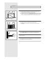
Attach the seal strip to the window.
8-1 Cut the adhesive-backed foam seal strip to the window width.
8-2 Remove the backing from the seal strip and attach the strip to the
underside of the bottom window.
8
Attach the window filler panels to the cabinet.
6-1 Install the top "L" shaped cannel with three Type B screws provided.
6-2 Slide the window filler panels and their frames into the channels on the
top and bottom of the cabinet and assemble them to the cabinet using
six Type B screws.
6
Install the cabinet in the window.
9-1 Place the cabinet into the window with the frame on the top of the
cabinet positioned just in front of the bottom window.
Pull the window down until it rests on the cabinet just behind the top
channel of the frame on the top of the cabinet.
9-2 Locate three screw holes along the cabinet bottom front edge.
Center the cabinet, side to side, in the window and mount it to the
window stool using three Type A screws.
9
Attach the support brackets to the cabinet.
7-1 Select the Type D support bracket position that will place the bracket
near the outermost point on the window sill. In most cabinets this will
be the first set of holes. Using eight Type B screws, attach the
support brackets to each side of the cabinet bottom.
7-2 Thread the Type C bolts into the support brackets, making sure the
cabinet maintains a slightly downward slant to the outside.
A 1/4" slant, from the cabinet front to the rear, is necessary.
Use the level to determine the slant.
7
Top Channel
Type C Bolts
Type B
Screws
Top
Channel

Installation
Extend the window filler panels.
10-1 When the window is pulled down, the window should rest on the
cabinet just behind the window filler panel frames.
10-2 Slide the filler panels outward until they touch the sides of the window.
Secure the panels by putting four Type A screws through the mounting
holes in the panels and driving them into the window stool and sash.
10
Slide the air conditioner into the cabinet.
11-1 Carefully slide the air conditioner back into the cabinet.
11-2 Reinstall the air conditioner-to-cabinet retaining screws removed
in page 14.
11
Reinstall the grille.
Refer to page 14.
13
Install the window gasket.
Cut the window gasket to the window width and stuff it between the
window and the glass to prevent air and insects from getting into the room.
12
Check for air leaks.
Some installations may require additional sealing around the window and
air conditioner. Check for air leaks and seal.
14
Screw
Screw
E-16

E-17
Labor
1 Year (In home)
Parts
1 Year
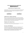
YOUR SAMSUNG ROOM AIR CONDITIONER
WARRANTY
Limited Warranty to Original Purchaser
Samsung will repair or replace, at our option, this product if found defective within the warranty
period beginning from the original date of purchase. This Samsung Product is warranted by
SAMSUNG ELECTRONICS America Inc. against manufacturing defects in materials or
workmanship for the period specified.
Limited 5-Years Compressor Warranty
Within one year of purchase Samsung Electronics America Inc. will provide a replacement
compressor if it is found to be defective in material or workmanship. During the existing four
years (second through fifth year) Samsung Electronics America Inc. will provide a replacement
only, without charge, if it is found to be defective in material or workmanship. Labor to install
the compressor during these existing four years is not included in the warranty. All warranty
repairs must be performed by a Samsung Authorized Service Station.
Obligation of the Original Owner
The original dated purchase receipt must be retained as proof of purchase and presented to
the Authorized Serivec Station before warranty services are rendered.
Exclusions of the Warranty
This warranty does not cover damage due to accident, fire, flood and/or other Acts of God:
misuse, incorrect line voltage, improper installation, improper or unauthorized repairs,
commercial use, or damages which occur in shipping. Exterior and interior finish and plastic
parts, are not covered under this warranty, Customer adjustments which are explained in the
instruction manual are not covered under the terms of this warranty. This warranty will
automatically be voided for any unit found with a missing or altered serial number.
This warranty is valid only on products purchased and used in America.

ELECTRONICS
Printed in Korea
SAMSUNG ELECTRONICS AMERICA INC.
105 Challenger Road Ridgefield Park, NJ 07660.
-
 1
1
-
 2
2
-
 3
3
-
 4
4
-
 5
5
-
 6
6
-
 7
7
-
 8
8
-
 9
9
-
 10
10
-
 11
11
-
 12
12
-
 13
13
-
 14
14
-
 15
15
-
 16
16
-
 17
17
-
 18
18


Ask a question and I''ll find the answer in the document
Finding information in a document is now easier with AI
Related papers
-
Samsung AW0595M User manual
-
-
-
-
-
-
-
-
-
 ABU HOSAN AHR24MEB User manual

