
Operating Manual
Twin-PVR Satellite
Receiver
UFS 821sw/821si
with hard disk

2
Preface
Dear customer,
this Operating Manual is intended to help you make the
fullest use of the extensive range of functions offered by
your new satellite receiver.
We have tried to make the operating instructions as easy
as possible to understand, and to keep them as concise as
possible. To help you understand particular specialist terms
that cannot be translated, we have added a short glossary
at the end of the manual.
The power switch is an environmentally friendly feature. If
you will not be using your receiver for a longer period, you
should therefore use the power switch to disconnect it from
the power supply to save energy. For shorter breaks, you
can switch the receiver to standby on the remote control,
which uses only a minimal amount of energy.
We wish you good reception and much pleasure using your
new PVR satellite receiver.
Your
KATHREIN Team
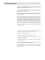
Important Information
The channels available on the satellites and transponders are
subject to continual change. In such cases, it is necessary
to reset the channels as the factory preset programming
corresponds to the situation on the date of manufacture.
The information for this reset can be found on the Internet
or in relevant magazines.
Your receiver is factory fitted with the latest software version.
We, however, always work on adapting the software to the
wishes of our customers and to developments in technology.
The “Software and Programme List Update” section contains
additional information.
Please keep the original packaging in case you need to
return the product at any time.
The hard disks are fragile due to their construction and
are only adequately protected in the receiver by the
original packaging.
If receiver is not shipped correctly the warranty on the
hard disk will be voided.
Make a note of the receiver’s basic settings, so as to be
able to restore them if necessary!
DiSEqC™ is a trademark of Eutelsat.

3
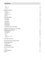
Contents
Preface 2
Contents 3
Safety Instructions - Important Notes 6
Receiver Features 7
Controls, Displays and Connections 8
Connection and Setup 9
Remote Control 12
First Installation 14
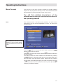
Operating Instructions 21
Menu Concept 21
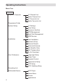
Menu Tree 22
Alphanumeric Inputs 23
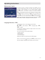
Language Selection - OSD 23
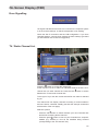
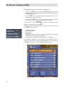
On-Screen Display (OSD) 24
Channel Notifications 24
Programme Information 24
Error Signalling 25
TV / Radio Channel List 25
Common Interface 27
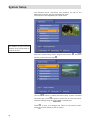
System Setup 30
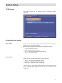
TV Settings 31
AV (Audio/Video) Settings 31
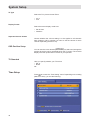
OSD Position Setup 32
TV Standard 32
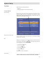
Time Setup 32
Common Interface 34
STB (Receiver) Management 35
System Information 35
Factory Default 35
Change Receiver Name 36
Hard Disk Management 36
Format Recording List 37
Format MP3 Archive 37
Format Photo Archive 37
USB Devices 37
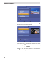
User Preference 38
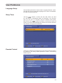
Language Setup 39
Sleep Timer 39
Parental Control 39
Receiver Lock 40
Age Rating Control 40
STB (Receiver) Management Lock 40
Change PIN 40
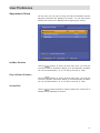
Appearance Setup 41
PVR setup 42
Automatic Time-Shift 42
Time-Shift Buffer Size 42

4
Contents
Hard Disk Management 42
Prompt on Recording 43
Default Record Duration 43
EPG Grabbing Setup 43
Videotext (Teletext) 44
Organise Channels 45
TV Channel List 46
Lock Channels 46
Rename Channels 46
Rearrange Channels 47
Skip Channels 47
Delete Channels 47
Radio Channel List 48
TV Favourite Lists 49
Create Favourite List 49
Rename Favourite List 49
Delete Favourite List 49
Add/Remove Channels (Favourite List) 49
Radio Favourite Lists 50
Twin Functions 51
Picture-in-Picture (PIP) 51
Time-Shift (time-delayed playback) 52
One-Touch Recording 52
Time-Shift 53
Time-Shift (time-delayed playback) 53
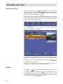
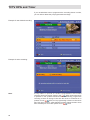
TVTV EPG and Timer 54
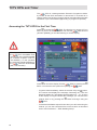
Accessing the TVTV EPG for the First Time 54
Accessing the TVTV EPG 55
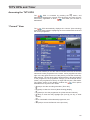
“Current” View 55
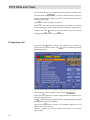
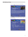
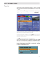
Programme List 56
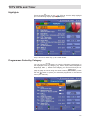
Highlights 57
Programmes Sorted by Category 57
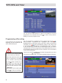
Search Function 58
Details 58
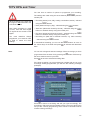
Programming a Recording 60
Timer List 63
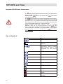
Important Additional Information 64
Key to Symbols 64
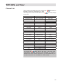
Channel List 65
Audio Settings 66
Recording 67
Recording Direct to Hard Disk (Store Time-Shift Recording) 67
Recording Direct to Hard Disk Immediately/Later 69
Recording List 70
Playing Back a Recording 70
Decoding a Recording 71
Edit Recordings 72
Delete 73
Rename 73
Copy 74
Cut 75

5
Merge 77
Deletion Block 78
Lock 78
Bookmarks 79
Multimedia/Games 80
MP3 Player 81
Organising MP3 Files 82
Photo Album 83
Organising Photo Files 85
Games 86
Applications 86
Installation Menu 87
First Installation 88
Antenna Setup 88
Tuner 1 Setup 89
Tuner 2 Setup 90
Channel Search 90
Motorised Antenna 92
Edit Satellite Data 96
Edit Transponders 97
On Air Download 97
Connecting up the Video/PVR 98
Software and Programme List Update 99
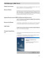
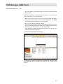
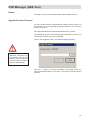
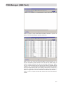
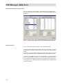
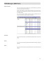
PVR Manager (USB Tool) 103
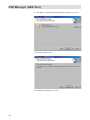
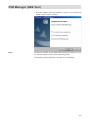
Standard Installation 103
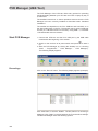
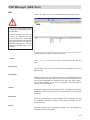
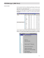
Start PVR Manager 106
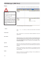
Recordings 106
MP3 109
Photos 110
Games 111
Upgrade Receiver Firmware 111
Channel List 112
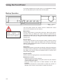
Using the Front Panel 118
Receiver to Receiver Data Transfer 119
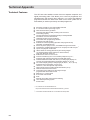
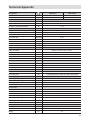
Technical Appendix 120
Technical Features 120
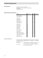
Accessories 122
Scart Socket Assignment 122
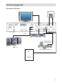
Connection Example 123
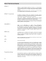
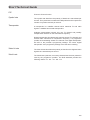
Short Technical Guide 124
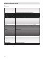
Glossary 126
Troubleshooting 127
Service 128
Contents

6
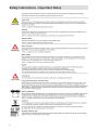
Safety Instructions - Important Notes

7
Receiver Features
The UFS 821 has two separate tuners for simultaneous reception of
two channels, and a hard disk for recording and playback.
Depending on constellation, you can
• view one programme and record another to hard disk,
• play back one recording from the hard disk and record one
programme to hard disk, or
• record two programmes to hard disk and play back one recording
from the hard disk, or
• record two programmes to hard disk and view a programme from one
of the programme packages being received.
To take advantage of all these opportunities, complex operating
procedures are necessary. You should therefore read this operating
manual thoroughly.
Our new UFS 821 multifunction satellite receiver has two independent
reception and signal processing circuitries as well as a computer hard
disk with a recording capacity of 160 GB.
This 160 GB hard disk enables over 100 hours of TV and radio
programmes to be recorded and replayed either simultaneously or
time-shifted without quality loss.
The tvtv EPG, which is professionally edited, provides free information
on some 60 channels without the need to change programme, even up
to a week in advance.
However, the really special attraction of this multi-talented unit lies in
the wealth of features offered by the receiver, such as the picture-in-
picture (PIP) function, transfer of the MPEG data stream to PC, and
import, playback and storage of MP3 files. The JPEG viewer allows
you to save your photographs on the hard disk and create a slide show.
The alphanumeric display shows channel names and radio data. The
multifunction control on the front of the unit matches the modern design
of the receiver and enables the receiver to be operated manually.
The receiver operating system is based on LINUX and offers additional
convenient functions.

8
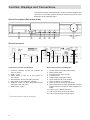
Controls, Displays and Connections
This section provides a brief description of all the controls, displays and
connections. The button symbols shown here will also be found in the
description of the operating steps.
View of front panel (flap folded down)
View of rear panel
Front Panel Controls and Displays
1. Common Interface for two CA modules for
Pay-TV cards*
)
2. USB 1.1 port
3. Menu button to call up or exit menus or
sub-menus
4. Record button to start recording manually
5. Play button to start playback manually
6. Stop/Exit button to stop playback/recording
manually or exit the menu
7. Multifunction control
Rear Panel Controls and Displays
1. On/Off switch (with mains disconnect)
2. Mains power cable
3. RS 232 port (for Service only)
4. S-Video output
5. Video output (composite colour)
6. Audio outputs (L/R) cinch sockets
7. Scart socket for TV connection
8. Scart socket for VCR/AUX connection
9. Optical data stream output (SPDIF/Sony Philips
Digital Interface Format) for Dolby Digital AC 3
audio
10. USB 2.0 port (USB-B connector)
11. LNB 2 input and loop-through output
12. LNB 1 input and loop-through output
*
)
CA modules and Pay TV cards are not included

9
Connection and Setup
The following section is intended specifically for specialist dealers. You
only need to read this section if you are carrying out the installation
yourself.
The “Connection Examples” section provides a sample configuration.
Do not connect the unit to the mains until all installation work has been
properly carried out.
Refer to the information in the “Safety Instructions” section.
Connecting the Unit
Sat IF Connections
Connect the Sat IF inputs on the receiver to the satellite reception
system.
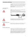
Use coaxial cable with a standard F connector.
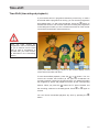
If the F connectors are not yet fitted on the cable, strip the insulation
from the cables as shown in the following illustration and carefully twist
the F connectors onto the ends of the cables until they are securely
fitted.
When fitting the connector, make sure that no wires from the braiding
are touching the inner conductor, so no short circuit can occur.
The quality of the reception signal depends on the connection.
Reception Requirements
Make sure that your own satellite antenna system is equipped at least
with a universal LNB for digital reception in the high-band range.
Reception System Presets
The presets for the control signals have been made for standard
reception systems, i.e. 14/18 V for polarity reversal and 22 kHz switching
signal for low/high band changeover on multi-feed reception systems.
If tone-burst switch matrices are used in the reception system, the default
selection in the installation menu, Antenna Setup, Tuner 1 and Tuner 2,
under “DiSEqC™ Switch”, must be changed. Refer to the “Installation
Menu” section on this, under “Antenna Setup”, “Tuner 1” and “Tuner 2”.
Be sure to follow the operating instructions for the matrix used.

10
Connection and Setup
Operation on one Antenna Connection
To enable you to utilise all the reception and recording properties of your
UFS 821 twin-PVR satellite receiver, such as
1. recording one programme and at the same time viewing any other
programme or zapping through the channels, and
2. recording two different programmes at the same time,
the two tuner inputs of the satellite receiver must each be supplied with
a dedicated satellite signal from the antenna system/Sat outlet.
The receiver tuner inputs are factory preset on the installation menu to
work with two separate Sat antenna connections.
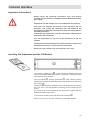
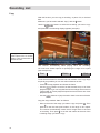
If you only have one antenna connection available, we recommend you
interconnect the output of tuner 1 and the input of tuner 2 by a coaxial
cable with F connectors.
For this, in “First Installation” for tuner input 2 select “Loop-through
mode” (see “First Installation” section).
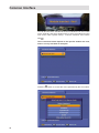
Press the
button to access the “Tuner Input” menu option, then
choose “Installation” and “First Installation”. Go through step-by-step
until you get to Tuner Setup. You can make the settings here.
Coaxial cable with F connectors

11
Note:
This will only work when receiving one satellite, not in multifeed
reception!
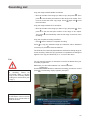
If only tuner 1 is connected (with no connection to tuner 2), the “Single
Mode” setting must be selected for the tuner input. You can then have
only the possibilities offered by a normal “single” receiver available to
you.
If this setting is not made, malfunctions will occur and the following
message will be displayed:
No signal!
Connection and Setup
TV and Video Recorder Connection
Connect the satellite receiver (TV Scart socket) and the TV set by a
Scart cable (see “Connection example”).
If your TV has a stereo feature, you can receive the sound in stereo via
the Scart connection.
Connect the satellite receiver (VCR/AUX Scart socket) and the video
recorder/PVR likewise by a Scart cable.
For system reasons, the same video signals are to be found on the
Scart outputs and on the video cinch output.
If you are recording using an external video recorder, remember not
to operate the receiver during recording, otherwise all the on-screen
displays will appear on your recording.
Audio Connection
If you want to play the sound on your hi-fi system, connect the audio
cinch sockets to the input sockets on the hi-fi system with an appropriate
cable (see “Connection Example”).
Optical Digital Output
The fibre-optic output is intended for the connection of a Dolby Digital
system (see “Connection Example”).
Inserting Batteries in the Remote Control
Remove the cover on the rear of the remote control.
Insert the two supplied batteries into the remote control. Ensure correct
polarity of the batteries; the + and – markings are indicated inside the
battery compartment.
Slide the cover back into the housing until it locks in place.
Used batteries are special waste!
Do not throw spent batteries into your domestic waste; take them to a
collection point for old batteries!
Electronic equipment is not domestic waste - in accordance with
directive 2002/96/EC OF THE EUROPEAN PARLIAMENT AND THE
COUNCIL dated 27
th
January 2003 on used electrical and electronic
equipment, it must be disposed of properly.
At the end of its service life, take this unit for disposal at a relevant
official collection point.
Though a restriction on this is that with tuner 2 you can only receive the
additional channels of the plane currently set by tuner 1 (e.g. Horizontal
High).

12
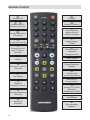
Remote Control
Sound on/off
...
Number input for
channels, timers etc.
Access main menu
Exit menus
Access Favourite list
Picture-in-picture
from 2
nd
tuner or
hard disk
Volume
Exit menu - back to
TV picture
Fast rewind
Playback
Hard disk contents
Pause (freeze-frame)
Time-shift
One-touch
recording
Standby
Videotext (Teletext)
Access channel
options Sound/
subtitles selection
Switch between
TV/radio
Access channel
notification
Programme info
AV mode
Channel selection
up/down
Confirm input
Access channel list
Cursor buttons
Access TVTV EPG
(Electronic
Programme Guide)
Fast forward
Stop recording/
playback

13
Remote control RC 660
The RC 660 remote control supports up to four devices (supplied as
standard with the RC 660) as well as the receivers of the UFD 5xx
(not UFD 552, 554, 558) and UFD 4xx families.
First switch all receivers off at the power switch.
To configure a receiver to an infrared code:
Switch on the relevant receiver.
On the remote control simultaneously press
Address 1 =
+
+
Then switch the receiver off again at the power switch and do the same
for the other units (
+
+
for second receiver;
+
+
for third receiver and
+
+
for fourth receiver).
Make sure only one receiver is on at a time!
To switch the remote control to an infrared code:
When you have configured all receivers to their infrared code, to switch
between units on the remote control do the following:
For the first receiver’s remote (address 1) press
+
; for the
second receiver
+
; for the third receiver
+
; and for the
fourth receiver
+
.
+
= Kathrein UFD 5xx code for remote control RC 400
The RC 600 and RC 650 remote controls cannot be replaced!
Remote Control

14
First Installation
Before using your unit for the first time, read the “Safety
Instructions” and “Connection and Setup” sections.
The “Connection Examples” section provides a sample
configuration.
Do not connect the unit to the mains until all installation work has
been properly carried out.
The guidance given in the “First Installation” section assumes
that the receiver has been properly connected, as per the “Safety
Instructions” and “Connection and Setup” sections.
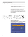
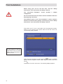
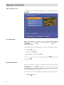
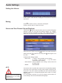
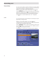
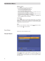
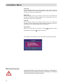
First switch your TV set on and select the AV programme position.
Switch on your receiver at the power switch on the rear of the unit.
The following display appears:
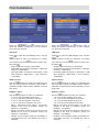
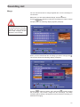
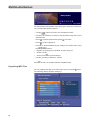
Select the menu language you want using the
buttons. Available
options: German, English, Turkish, Italian, Spanish, Polish, Dutch and
French.
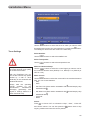
Press
to move to the next menu. The following display appears:
Also pay attention to the bars
at the bottom of the on-screen
display! They provide hints on
what to do next.

15
First Installation
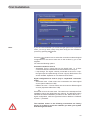
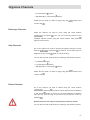
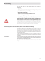
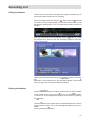
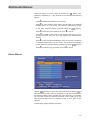
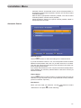
Note: If you are unsure whether you chose the right option from a previous
menu, you can go back a step at any time during the first installation
process by pressing the
button.
Press the
buttons here to select the connection mode and signal
configuration for the second tuner set on the receiver by you or the
engineer.
You have the following options:
Connection mode for tuner 2
- Separated: Tuner 2 (input) has its own signal input, i.e. a direct
connection between the antenna socket and the tuner 2 input
- Loop-through: The signal currently connected to the tuner 1 loop-
through output is looped-through to tuner 2 (input). Refer also to the
section headed “Operation on one Antenna Connection”
Signal configuration for tuner 2 (only in “Separated” connection
mode)
- Same with tuner 1: Both tuners are connected to the same signal
source (same cable from LNB)
- Different to tuner 1: The two tuners are connected to different signal
sources (separate cables from LNB)
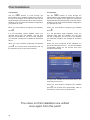
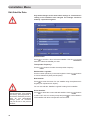
Press
to move to the next menu. The notes on the subsequent First
Installation menus are divided into two columns. The left-hand column
indicates the further installation procedure for the “Same with tuner 1”,
signal configuration, while the right-hand column details the “Different
to tuner 1” procedure.
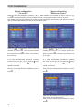
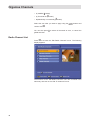
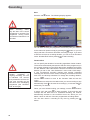
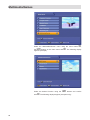
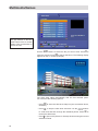
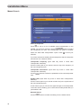
The satellites shown in the following screenshots are factory
preset. To be able to receive the satellites you want, your system
must be aligned to them!

16
Press the
and
buttons here to select the
satellites you want tuners 1 and 2 to receive signals
from. When you press
to confirm your selection,
the chosen satellite is moved into the tuner satellite
list on the right.
If you have unintentionally transferred a satellite
into the list on the right, you can press the
button
to switch lists and then press
to remove the
satellite concerned.
When you have selected all the satellites you want,
press
.
First Installation
Press the
and
buttons here to select the
satellites you want tuner 1 to receive signals from.
When you press
to confirm your selection, the
chosen satellite is moved into the tuner satellite list
on the right.
If you have unintentionally transferred a satellite
into the list on the right, you can press the
button
to switch lists and then press
to remove the
satellite concerned.
When you have selected all the satellites you want,
press
.
Select here the satellites you want tuner 2 to receive
signals from, as you did for tuner 1.
When you have selected all the satellites you want,
press
.
Signal configuration
“As tuner 1”
Signal configuration
“Different to tuner 1”
Press
to view the satellites by continent - that is, which satellites are accessible on which continent. The
continents are displayed above the list of satellite names. The selected continent is shown in yellow.
The satellites from the pre-programmed channel list are automatically pre-entered in the right-hand column,
and can be changed/deleted according to your reception system.

17
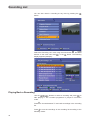
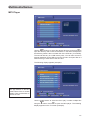
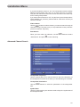
First Installation
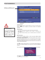
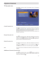
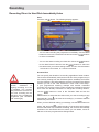
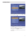
Press the
and
buttons here to
select the satellite configuration for each satellite
you previously selected.
LNB Type:
Press
to open the LNB Settings menu. Use the
buttons to make your selection. To confirm
your selection use the
buttons to select “OK”
and press
.
- Single (LNB Low frequency 9750 MHz)
- Dual (LNB Low frequency 9750 MHz + LNB High
frequency 10600 MHz)
- Universal (LNB Low frequency 9750 MHz + LNB
High frequency 10600 MHz + Limit frequency
11700 MHz)
22kHz Control:
Use the
buttons to make your selection (On/
Off). The 22kHz signal is needed to switch LNBs in
multifeed reception and to switch between Low and
High band.
DiSEqC™ Input:
Use the
buttons to make your selection.
- 1 of 4: for the first satellite of the tuner
- 2 of 4: for the second satellite of the tuner
- 3 of 4: for the third satellite of the tuner
- 4 of 4: for the fourth satellite of the tuner
- Mini A: Tone-burst control signal 1 for the first
satellite of the tuner (if reception system not
DiSEqC™ compatible)
- Mini B: Tone-burst control signal 2 for the second
satellite of the tuner (if reception system not
DiSEqC™ compatible)
- Disable: If your reception system is not DiSEqC™
compatible and only one satellite per tuner is
selected.

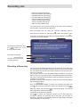
18
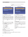
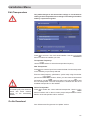
Transponder:
Use the
buttons to scroll through the
transponders of the satellite highlighted in yellow at
the top of the display. At the right you will see the
signal strength of the transponder on the two tuners,
enabling you to check that the satellite configuration
you just set up is OK.
When you have finished configuring this satellite,
press
.
If in the preceding “Select Satellite” menu you
selected more than one satellite, you will now
see the configuration for the next of the satellites
you selected. Configure the satellite as described
above.
When you have finished configuring the satellite
press
. The receiver then automatically calls up
the selection menu for the channel search.
First Installation
Transponder:
Use the
buttons to scroll through the
transponders of the satellite highlighted in yellow at
the top of the display. At the right you will see the
signal strength of the transponder on the two tuners,
enabling you to check that the satellite configuration
you just set up is OK.
When you have finished configuring the satellite
press
.
If in the preceding “Select Satellite” menu you
selected more than one satellite, you will now
see the configuration for the next of the satellites
you selected. Configure the satellite as described
above.
When you have configured all the satellites you
previously selected for tuner 1, you see the satellite
configuration display for the second tuner (see
example screenshot):
Configure the satellites for the second tuner in the
same way as for tuner 1.
When you have finished configuring the satellite
press
. The receiver then automatically calls up
the selection menu for the channel search.
The notes on first installation are unified
once again from this point!

19
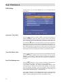
Use the
buttons to make the settings.
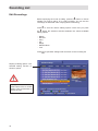
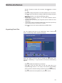
Channel Search
Use the
buttons to select whether you want to use the factory
default channel list or whether you want to search for more/new
channels.
FTA CA Select:
- All: FTA (free-to-air) and encoded channels are searched for
- FTA: Only free-to-air channels, such as ZDF in Germany, are
searched for
- CA: Only encoded channels, such as Austria’s ORF, are searched
for
Network Search
If you set the network search to “Off”, only the factory stored
transponders of the satellites you previously selected will be scanned
for new as yet unlisted channels.
If you set the network search to “On”, the transponder network enables
additional transponders that have not yet been stored to be located.
They are then stored and scanned for new channels in the same way
as the existing transponders.
Press
to start the channel search, or if you set the channel search to
“Off” you are guided straight to the next item in the first installation
process.
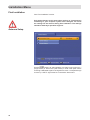
If the search is successful, you see the following message (example):
First Installation
Press
to confirm storing of the newly found channels and move on
to the next step in first installation.
Encoded channels
can only be decoded with
a CA module and matching
Smartcard. CA modules
and Smartcards are not
included in the product
package. Please contact
your Pay-TV provider.
Number of channels in the
pre-programmed channel list

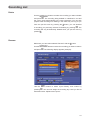
20
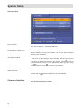
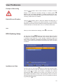
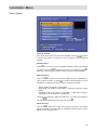
Use the
buttons here to select the time recording mode:
• Manual or
• Auto (receiver takes time from preset channel)
Use the
buttons to make the settings.
Set Local Time (time zone difference)
Press
to set the variance from UMTC (Universal
Mean Time Coordinate; formerly Greenwich Mean
Time) and Winter/Summer time. At the bottom of the
screen you see a listing of major cities to provide
an indication of which time zone you have just set.
Example: for Berlin (Germany) you need to enter
+1 hour. Use the
buttons to make the
setting.
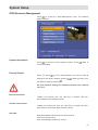
Day
Select the current day’s date here. Press
to
display a calendar. Select the day using the cursor
buttons (
). If the right month and year
are not displayed, you can select as follows:
• Previous month (
button)
• Next month (
button)
• Previous year (
button)
• Next year (
button)
Press
to confirm your selection.
Current Time
Use the number pad to key in the current time
here. The position at which the number needs to be
entered is automatically underlined.
First Installation
“Manual” time setting
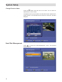
“Auto” time setting
Use the
buttons to make the settings.
Set Local Time (time zone difference)
Press
to set the variance from UMTC (Universal
Mean Time Coordinate; formerly Greenwich Mean
Time) and Winter/Summer time. At the bottom of the
screen you see a listing of major cities to provide
an indication of which time zone you have just set.
Example: for Berlin (Germany) you need to enter
+1 hour. Use the
buttons to make the
setting.
Time Setup Channel
If you have selected automatic time recording, set
the channel here from which you want the receiver
to get the time. Press
to call up a channel list
from which you can select the channel you want
using the
buttons. Press
to confirm your
selection.
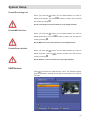
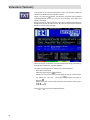
Setup Time Now
Press
to set the time immediately. It may take
a few seconds for the right time and date to be
displayed.
Use the
buttons to select “OK” and press
to complete first installation.
Then press
to view the TV picture.
Page is loading ...
Page is loading ...
Page is loading ...
Page is loading ...
Page is loading ...
Page is loading ...
Page is loading ...
Page is loading ...
Page is loading ...
Page is loading ...
Page is loading ...
Page is loading ...
Page is loading ...
Page is loading ...
Page is loading ...
Page is loading ...
Page is loading ...
Page is loading ...
Page is loading ...
Page is loading ...
Page is loading ...
Page is loading ...
Page is loading ...
Page is loading ...
Page is loading ...
Page is loading ...
Page is loading ...
Page is loading ...
Page is loading ...
Page is loading ...
Page is loading ...
Page is loading ...
Page is loading ...
Page is loading ...
Page is loading ...
Page is loading ...
Page is loading ...
Page is loading ...
Page is loading ...
Page is loading ...
Page is loading ...
Page is loading ...
Page is loading ...
Page is loading ...
Page is loading ...
Page is loading ...
Page is loading ...
Page is loading ...
Page is loading ...
Page is loading ...
Page is loading ...
Page is loading ...
Page is loading ...
Page is loading ...
Page is loading ...
Page is loading ...
Page is loading ...
Page is loading ...
Page is loading ...
Page is loading ...
Page is loading ...
Page is loading ...
Page is loading ...
Page is loading ...
Page is loading ...
Page is loading ...
Page is loading ...
Page is loading ...
Page is loading ...
Page is loading ...
Page is loading ...
Page is loading ...
Page is loading ...
Page is loading ...
Page is loading ...
Page is loading ...
Page is loading ...
Page is loading ...
Page is loading ...
Page is loading ...
Page is loading ...
Page is loading ...
Page is loading ...
Page is loading ...
Page is loading ...
Page is loading ...
Page is loading ...
Page is loading ...
Page is loading ...
Page is loading ...
Page is loading ...
Page is loading ...
Page is loading ...
Page is loading ...
Page is loading ...
Page is loading ...
Page is loading ...
Page is loading ...
Page is loading ...
Page is loading ...
Page is loading ...
Page is loading ...
Page is loading ...
Page is loading ...
Page is loading ...
Page is loading ...
Page is loading ...
Page is loading ...
-
 1
1
-
 2
2
-
 3
3
-
 4
4
-
 5
5
-
 6
6
-
 7
7
-
 8
8
-
 9
9
-
 10
10
-
 11
11
-
 12
12
-
 13
13
-
 14
14
-
 15
15
-
 16
16
-
 17
17
-
 18
18
-
 19
19
-
 20
20
-
 21
21
-
 22
22
-
 23
23
-
 24
24
-
 25
25
-
 26
26
-
 27
27
-
 28
28
-
 29
29
-
 30
30
-
 31
31
-
 32
32
-
 33
33
-
 34
34
-
 35
35
-
 36
36
-
 37
37
-
 38
38
-
 39
39
-
 40
40
-
 41
41
-
 42
42
-
 43
43
-
 44
44
-
 45
45
-
 46
46
-
 47
47
-
 48
48
-
 49
49
-
 50
50
-
 51
51
-
 52
52
-
 53
53
-
 54
54
-
 55
55
-
 56
56
-
 57
57
-
 58
58
-
 59
59
-
 60
60
-
 61
61
-
 62
62
-
 63
63
-
 64
64
-
 65
65
-
 66
66
-
 67
67
-
 68
68
-
 69
69
-
 70
70
-
 71
71
-
 72
72
-
 73
73
-
 74
74
-
 75
75
-
 76
76
-
 77
77
-
 78
78
-
 79
79
-
 80
80
-
 81
81
-
 82
82
-
 83
83
-
 84
84
-
 85
85
-
 86
86
-
 87
87
-
 88
88
-
 89
89
-
 90
90
-
 91
91
-
 92
92
-
 93
93
-
 94
94
-
 95
95
-
 96
96
-
 97
97
-
 98
98
-
 99
99
-
 100
100
-
 101
101
-
 102
102
-
 103
103
-
 104
104
-
 105
105
-
 106
106
-
 107
107
-
 108
108
-
 109
109
-
 110
110
-
 111
111
-
 112
112
-
 113
113
-
 114
114
-
 115
115
-
 116
116
-
 117
117
-
 118
118
-
 119
119
-
 120
120
-
 121
121
-
 122
122
-
 123
123
-
 124
124
-
 125
125
-
 126
126
-
 127
127
-
 128
128


Ask a question and I''ll find the answer in the document
Finding information in a document is now easier with AI
Related papers
-
Kathrein UFS 712sw User manual
-
-
Kathrein UFS 651si Operating instructions
-
-
Kathrein 20210158 Owner's manual
-
-
-
-
-
Other documents
-
 Ten-Haaft D5000 Operating Instructions Manual
-
 Meanta CR9000PVR User manual
-
Topfield TF 5400 PVR combo User manual
-
Triax S-HD 207 Operating instructions
-
-
-
 Traxis DBS 3500 Operating instructions
-
Strong SRT 7003 User manual
-
Humax hdci 2000 hdtv User manual
-
TechniSat HD-Vision DVB-S User manual


