Sony Sony VPLEW225 User manual

Category
Data projectors
Type
User manual
4-435-798-11 (1)
© 2012 Sony Corporation
Data
Projector
Operating Instructions
Before operating the unit, please read this manual and supplied Quick Reference Manual
thoroughly and retain it for future reference.
VPL-EW275/EW245/EW225
VPL-EX275/EX271/EX245/EX241/EX225/EX221
Not all models are available in all countries and area. Please check
with your local Sony Authorized Dealer.
2
Table of Contents
Table of Contents
Overview
Location and Function of Controls .... 4
Main Unit .....................................4
Connector Panel ...........................5
Remote Commander and Control
Panel Keys ................................. 6
Preparation
Connecting the Projector ................... 9
Connecting a Computer ................9
Connecting a Video
equipment ................................ 10
Connecting a microphone .......... 12
Connecting a USB memory
device ...................................... 12
Connecting a USB wireless LAN
module .................................... 13
Connecting an External Monitor and
Audio Equipment .................... 13
Projecting/Adjusting an
Image
Projecting an Image ......................... 14
Adjusting the Projected image ... 15
Turning Off the Power ................ 18
Adjustments and Settings
Using a Menu
Using a MENU ................................ 19
The Picture Menu .............................20
The Screen Menu .............................21
The Function Menu .......................... 25
The Operation Menu ........................ 26
The Connection/Power Menu ...........27
The Installation Menu ......................29
The Information Menu .....................30
Network
Using Network Features ...................31
Displaying the Control Window of
the Projector with a Web
Browser ...................................31
Confirming the Information
regarding the Projector ............32
Operating the Projector from a
Computer .................................32
Using the e-mail report
Function ...................................33
Presentation Function via
Network
Using Presentation Function via
Network .........................................35
Installing Projector Station for
Network Presentation ..............35
Starting Projector Station for
Network Presentation ..............35
Projecting an Image ....................36
Connection Settings ....................36
Using the Controller ...................37
Projecting an Image using
USB Connection
Projecting an Image using USB
Connection ....................................38
Starting USB Display .................38
Projecting an Image ....................38
3
Table of Contents
Using the Controller ...................38
USB Media Viewer
Using USB Media Viewer ................39
Thumbnail Mode ........................40
Option Menu ...............................40
Display Mode .............................41
Option Menu ...............................41
Slideshow Mode .........................41
Option Menu ...............................42
Others
Indicators ..........................................43
Messages List ...................................44
Troubleshooting ...............................45
Replacing the Lamp .........................47
Cleaning the Air Filter .....................49
Specifications ...................................50
Projection Distance ..........................58
Dimensions .......................................72
Index .................................................78
4
Location and Function of Controls
B Overview
Location and Function of Controls
a Focus ring (page 15)
b Zoom ring (page 15)
c Lens
d Remote control detector
e ON/STANDBY indicator
(page 43)
f LAMP/COVER indicator
(page 43)
g Front feet (adjustable) (page 16)
h Foot adjust button (page 16)
i Air filter cover/Ventilation holes
(intake) (page 49)
j Lamp cover (page 47)
k Ventilation holes (exhaust)
Do not place anything near the ventilation
holes as this may cause internal heat
buildup. Do not place your hand near the
ventilation holes and the circumference as
this may cause injury.
l Speaker (VPL-EW275/EW245/
EW225/EX275/EX245/EX225
only)
m Connector panel (page 5)
n Security bar
Connects to a commercially available
security chain or wire.
o Security lock
Connects to an optional security cable
manufactured by Kensington.
For details, visit Kensingtons web site.
http://www.kensington.com/
p Control panel keys (page 6)
Main Unit
5
4
3
2
1
6
8
7
9
qa
qs
7
8
0
Caution
qh
qf
qd
q
g
5
Location and Function of Controls
Overview
VPL-EW275/EW245/EW225/EX275/EX245/EX225
VPL-EX271/EX241/EX221
Input (pages 9, 10)
a INPUT A
Video: RGB/YPBPR input connector
(RGB/YP
BPR)
Audio: Audio input connector (AUDIO)
b INPUT B
Video: RGB input connector (RGB)
Audio: Audio input connector (AUDIO)
c INPUT C
Video: HDMI input connector (HDMI)
Audio: HDMI input connector (HDMI)
d S VIDEO (S VIDEO IN)
Video: S video input connector (S
VIDEO IN)
Audio: Audio input connector (L
(MONO) AUDIO/R)
e VIDEO (VIDEO IN)
Video: Video input connector (VIDEO)
Audio: Audio input connector (L
(MONO) AUDIO/R)
The audio inputs of S VIDEO and VIDEO
are shared.
The audio input connector and audio output
from the HDMI connector are available only
on VPL-EW275/EW245/EW225/EX275/
EX245/EX225.
Output (page 13)
f OUTPUT
Video: Monitor output connector
(MONITOR)
Audio: Audio output connector
(AUDIO)
Connector Panel
54
4
5
7
6
1
29
8q;3
qs
qa
54
7
6
1
29
8q;3qa
Notes
6
Location and Function of Controls
This connector outputs the projected image
or audio only when INPUT A or INPUT B is
used.
The audio output connector is available only
on VPL-EW275/EW245/EW225/EX275/
EX245/EX225.
Others
g RS-232C connector (RS-232C)
RS-232C compatible control connector.
Connects the computer’s RS-232C
connector and the RS-232C cross cables.
h LAN connector (page 31)
i AC IN () socket
Connects the supplied AC power cord.
j USB connector (Type A) ( )
(pages 12, 39)
k USB connector (Type B) ( )
(page 38)
l Microphone input ( )
Microphone input is available only on VPL-
EW275/EW245/EW225/EX275/EX245/
EX225.
Remote Commander
Control Panel Keys
a Turning on the power/Going to
standby mode
?/1 (On/Standby) key
b Selecting an input signal
(page 14)
INPUT key
c Operating a menu (page 19)
MENU key
RESET key
ENTER /V/v/B/b (arrow) keys
RETURN key
d Adjusting the image (page 15)
ASPECT key (page 21)
KEYSTONE key (page 17)
PATTERN key
This function is not available.
APA (Auto Pixel Alignment) key
*
(page 17)
*
Use this key when inputting a computer
signal via the RGB input connector
(INPUT A or INPUT B).
Notes
Note
Remote Commander and Control Panel Keys
2
3
4
5
6
1
4
7
INPUT
MENU
APA ECO MODE
RETURN
ASPECT
D ZOOM
KEYSTONE
ENTER
VOLUME
PATTERN
FREEZE
BLANK
MUTING
RESET
3
6
12
Note
7
Location and Function of Controls
Overview
e Using various functions during
projecting
D ZOOM (Digital Zoom) +/– key
*
Enlarges a portion of the image while
projecting.
1 Press the D ZOOM + key to display
the digital zoom icon on the projected
image.
2 Press the V/v/B/b keys to move the
digital zoom icon to the point on the
image you want to enlarge.
3 Press the D ZOOM + key or the D
ZOOM – key repeatedly to change the
enlargement ratio. The image can be
enlarged up to 4 times.
Press the RESET key to restore the
previous image.
BLANK key
Cuts off the projected image
temporarily. Press again to restore the
previous image. Picture muting helps
reduce power consumption.
MUTING key (VPL-EW275/EW245/
EW225/EX275/EX245/EX225 only)
Mutes the audio output temporarily.
Press again to restore the previous
volume.
VOLUME +/– key (VPL-EW275/
EW245/EW225/EX275/EX245/
EX225 only)
Adjusts the volume output.
FREEZE key
This function is not available.
* Use this key when inputting a computer
signal. But it may not be used depending
on the resolution of the input signal.
f Setting the energy–saving mode
easily
ECO MODE key
Energy-saving mode can be set easily.
Energy-saving mode consists of “Lamp
Mode,” “With No Input,” “With Static
Signal” and “Standby Mode.
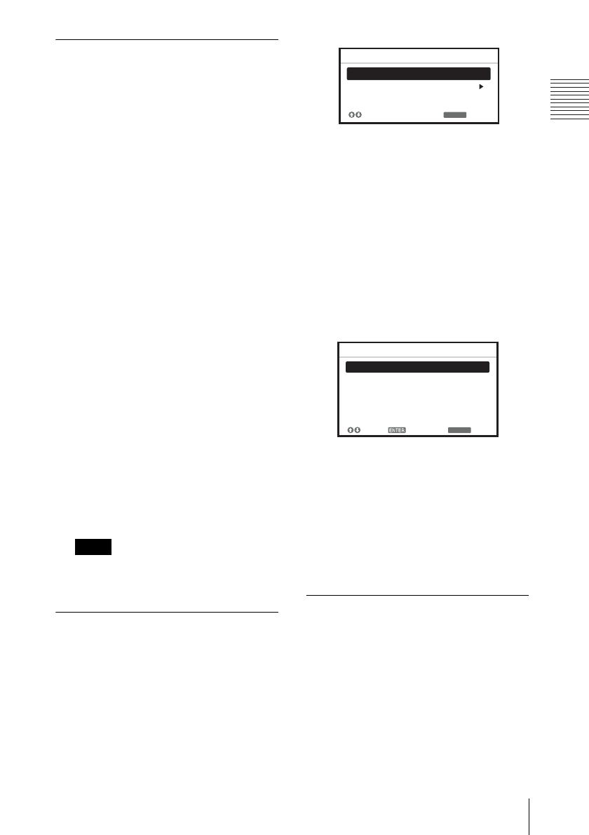
1 Press the ECO MODE key to display
the ECO Mode menu.
2 Press the V/v key or ECO MODE key
to select “ECO” or “User” mode.
ECO: Sets each mode to the optimum
energy-saving value.
Lamp Mode: Low
With No Input: Standby
With Static Signal: Lamp
Dimming
Standby Mode: Low
User: Sets each item of the ECO
Mode menu as you desire (go to
step 3).
3 Select “User” then press the b key.
The setting items appear.
4 Press the V/v key to select the item
then press the ENTER key.
5 Press the V/v key to select the setting
value.
6 Press the ENTER key.
The screen returns to the User screen.
For details on ECO Mode settings, see
“Lamp Mode,” “With No Input,” “With
Static Signal” and “Standby Mode” on
the Connection/Power menu (page 27).
Others
g Infrared transmitter
About remote commander operation
Direct the remote commander toward the
remote control detector.
The shorter the distance between the
remote commander and the projector is,
the wider the angle within which the
remote commander can control the
projector becomes.
Note
RETURN
ECO
User
ECO Mode
:Sel
:Back
RETURN
Lamp Mode High
Auto Power Saving
Standby Mode
Off
With No Input
Lamp Dimming
With Static Signal
Standard
User
:S el
:S et
:Back
8
Location and Function of Controls
Make sure that nothing obstructs the
infrared beam between the remote
commander and the remote control
detector on the projector.
9
Connecting the Projector
Preparation
B Preparation
Connecting the Projector
Make sure all the equipment is powered off when connecting the projector.
Use the proper cables for each connection.
Insert the cable plugs firmly; Loose connections may reduce performance of picture signals or
cause a malfunction. When pulling out a cable, be sure to grip it by the plug, not the cable itself.
For more information, refer also to the instruction manuals of the equipment you are connecting.
Use a no-resistance audio cable.
Connection with a computer is explained for each input signal.
INPUT A/INPUT B
The audio input connector is available only on VPL-EW275/EW245/EW225/EX275/EX245/
EX225.
It is recommended that you set the resolution of your computer to 1280 × 800 pixels (VPL-EW275/
EW245/EW225) or 1024 × 768 pixels (VPL-EX275/EX271/EX245/EX241/EX225/EX221) for
the external monitor.
INPUT C
Notes
Connecting a Computer
For connecting a computer with an RGB output connector.
RGB output
connector
Audio output
connector
Mini D-sub 15-pin cable (supplied)
Computer
Audio cable (Stereo mini plug)
(not supplied)
Notes
For connecting a computer with an HDMI output connector.
HDMI output
connector
HDMI cable
(not supplied)
Computer
10
Connecting the Projector
Audio output from the HDMI connector is available only on VPL-EW275/EW245/EW225/
EX275/EX245/EX225.
Use HDMI-compatible equipment and cable(s) that have an HDMI logo on them.
The HDMI connector of this projector is not compatible with DSD (Direct Stream Digital) Signal
or CEC (Consumer Electronics Control) Signal.
USB connector (Type B) ( )
For connecting to a computer with a USB connector (“Projecting an Image using USB
Connection” (page 38)).
Connections with a VHS video deck, DVD player, or BD player are explained for each input
signal.
S VIDEO IN
For connecting video equipment with an S-video output connector.
The audio input connector is available only on VPL-EW275/EW245/EW225/EX275/EX245/
EX225.
Notes
Connecting a Video equipment
USB A-B cable (not
supplied)
Computer
USB connector
(Type A)
Note
S video output
connector
Audio output
connector
S video cable (not supplied)
Computer
Audio cable (Phono plug × 2)
(not supplied)
11
Connecting the Projector
Preparation
VIDEO IN
For connecting video equipment with a video output connector.
The audio input connector is available only on VPL-EW275/EW245/EW225/EX275/EX245/
EX225.
INPUT A
For connecting video equipment with a YPBPR output connector.
The audio input connector is available only on VPL-EW275/EW245/EW225/EX275/EX245/
EX225.
Note
Note
Video cable (not supplied)
Audio cable (Phono plug × 2 – stereo mini plug) (not supplied)
Video output
connector
Audio output
connector
Video equipment
Component – Mini D-sub 15-pin cable (not supplied)
Audio cable (Phono plug × 2 – stereo mini plug) (not supplied)
Video equipment
YP
BPR output
connector
Audio output
connector
12
Connecting the Projector
INPUT C
Audio output from the HDMI connector is available only on VPL-EW275/EW245/EW225/
EX275/EX245/EX225.
Use HDMI-compatible equipment and cable(s) that have an HDMI logo on them.
The HDMI connector of this projector is not compatible with DSD (Direct Stream Digital) Signal
or CEC (Consumer Electronics Control) Signal.
Microphone ( )
For connecting a microphone.
The microphone input is available only on VPL-EW275/EW245/EW225/EX275/EX245/EX225.
Only dynamic microphones are supported.
USB connector (Type A) ( )
For connecting a USB memory device (“Using USB Media Viewer” (page 39)).
Notes
Connecting a microphone
Notes
Connecting a USB memory device
Video equipment
HDMI cable
(not supplied)
HDMI output
connector
For connecting video equipment with an HDMI output connector.
Microphone
(not supplied)
USB memory device
(not supplied)
13
Connecting the Projector
Preparation
USB connector (Type A) ( )
For connecting a USB wireless LAN module IFU-WLM3 (not supplied) (“Presentation
Function via Network” (page 35)).
Undesignated USB wireless LAN modules do not work.
When connecting/disconnecting the USB wireless LAN module, make sure that the projector is in
Standby mode (Standby Mode: “Low”), or the AC power cord is unplugged from the wall outlet.
OUTPUT
Projected images or input audio can be output to display equipment such as a monitor or audio
equipment such as speakers with a built-in amplifier.
The audio input connector is available only on VPL-EW275/EW245/EW225/EX275/EX245/
EX225.
Projected images and audio can be output.
Connecting a USB wireless LAN module
Notes
Connecting an External Monitor and Audio Equipment
Notes
USB wireless LAN module
IFU-WLM3 (not supplied)
Audio cable
(stereo mini plug)
(not supplied)
Audio input
connector
Mini D-sub 15-pin cable
(supplied)
RGB input
connector
Audio equipment
Display equipment
14
Projecting an Image
B Projecting/Adjusting an Image
Projecting an Image
The size of a projected image depends on the distance between the projector and screen. Install
the projector so that the projected image fits the screen size. For details on projection distances
and projected image sizes, see
“Projection Distance” (page 58).
1 Plug the AC power cord into the wall
outlet.
2 Connect all equipment to the projector
(page 9).
3 Press the ?/1 key to turn on the unit.
4 Turn on the connected equipment.
5 Select the input source.
Press the INPUT key on the projector to
display the menu for switching input
signal on the screen. Press the INPUT
key repeatedly, or press the
V/v key to
select an image to be projected.
6 When projecting a computer image,
switch your computer’s output to
external display.
The method to switch the output varies
depending on the type of computer.
(Example)
To project image files stored in a USB
memory device, see “USB Media
Viewer” (page 39). To project an image
using USB Connection, see “Projecting
an Image using USB Connection
(page 38). To use Presentation Function
via Network, see “Presentation Function
via Network” (page 35).
Computer
Video equipment
Projector
Wall outlet
1
2
5
4
3
6
+
15
Projecting an Image
Projecting/Adjusting an Image
7 Adjust the focus, size and position of
the projected image (page 15).
Adjusting the Projected image
Focus Size (Zoom) Position
Focus ring
Zoom ring
Foot
adjust
button
Front feet
(adjustable)
16
Projecting an Image
Adjusting the tilt of the projector with the front feet (adjustable)
By changing the tilt of the projector with the foot adjust buttons/front feet (adjustable), you can
adjust the position of the projected image.
How to adjust the angle
1 Press and hold the foot adjust buttons.
2 Lift up the front of the projector to
adjust the angle.
3 Release the foot adjust buttons.
4 Turn the front feet (adjustable) to set
the angle of the projector precisely.
Be careful not to let the projector down on your fingers.
Do not push hard on the top of the projector with the front feet (adjustable) extended.
Changing the aspect ratio of the projected image
Press the ASPECT key on the remote commander to change the aspect ratio of the projected
image. You can also change the setting in Aspect of the Screen menu (pages 21, 23).
Notes
17
Projecting an Image
Projecting/Adjusting an Image
Correcting trapezoidal distortion of the projected image (Keystone feature)
Normally the Keystone feature automatically adjusts the projected image. The Keystone
feature may not work automatically if the screen is tilted. In this case, set Keystone manually.
1 Press the KEYSTONE key on the remote
commander or select V Keystone in the
Installation menu.
2 Use the V/v/B/b keys to set the value. The
higher the value, narrower the top of the
projected image. The lower the value, the
narrower the bottom.
Since the Keystone adjustment is an electronic
correction, the image may be deteriorated.
Automatically adjusts Phase, Pitch and Shift of projected image while a
signal is input from a computer (APA (Auto Pixel Alignment))
Press the APA key on the remote commander. Press again to cancel adjusting during the setting.
You can also set APA in the Screen Menu (page 22). If Smart APA in the Function menu is set
to “On”, executes APA automatically when a signal is input (page 25).
Note
Increase the number
towards plus
Increase the number
towards minus
18
Projecting an Image
1 Press the ?/1 key on the unit or the remote commander.
The projector starts shutdown and turns off. If you press the ?/1 key within 10 seconds
again, shutdown is cancelled.
2 Unplug the AC power cord from the wall outlet.
To turn off without displaying confirmation message
Press and hold the ?/1 key on the unit for a few seconds (page 44).
ECO gauge
This gauge indicates the current effectiveness of the projectors ECO function. (For details on
the ECO function, see “ECO MODE key” (page 7) and “ECO” (page 27).)
The leaf icons are displayed when the projector is shut down. The number of displayed icons
varies according to how much energy is saved as a result of using the ECO function.
Turning Off the Power
ECO gauge
19
Using a MENU
Adjustments and Settings Using a Menu
B Adjustments and Settings Using a Menu
Using a MENU
The menu displays used for the explanation below may be different depending on the model you are
using.
1 Press the MENU key to display the
menu.
2 Select the setting menu.
Use the V/v key to select the setting
menu then press the b key or ENTER
key.
3 Select the setting item.
Use the V/v key to select the setting
menu then press the b key or ENTER
key.
To return to the selection screen of the
setting menu, press the B or RETURN
key.
4 Make the setting or adjustment for the
selected item.
The setting method varies, depending on
the setting item.
If the next menu window is displayed,
select the item according to the
operations in step 3 and then press the
ENTER key to register the setting.
To return to the selection screen of the
setting items, press the B or RETURN
key. You can press the RESET key to
reset an item to its factory setting value
to aid setting.
Using a pop-up menu
Press the V/v/B/b key to select an item.
A selected item takes effect
immediately, except “Language”, which
will take effect after you press the
ENTER key.
Using the setting menu
Press the V/v key to select the item.
Press the ENTER key to register the
setting and return to the previous screen.
Using the adjustment menu
To increase the value, press the V/b key
and to decrease the number, press the
v/B key. Press the ENTER key to
register the setting and return to the
previous screen.
5 Press the MENU key to clear the
menu.
The menu disappears automatically if no
operation is performed.
Note
Picture Mode Standard
Reset
Contrast
Brightness
Color
Hue
Color Temp.
Sharpness
Expert Setting
:S el :Set :Back
Picture
Low
Setting menu
80
50
50
50
5
Picture Mode Standard
Reset
Contrast
Brightness
Color
Hue
Color Temp.
Sharpness
Expert Setting
:S el :Set :Back
Picture
Low
Setting items
RETURN
Picture Mode
Dynamic
Standa rd
:Back
:S el
Cinema
Game
Blackboard
Presentation
Adjust
Back
Contrast
20
The Picture Menu
The Picture Menu
The Picture is used to adjust the picture for each input signal.
*1: When a computer signal is input, this option is available.
*2: The settings in the Picture return to their factory defaults, except for Picture Mode.
*3: When a video signal is input, this option is available.
*4: When the signal without color burst signal is input, this option is unavailable.
*5: When an analog TV signal is input, this option may not available, depending on the color system.
*6: When “Picture Mode” is set to the item other than “Presentation” or “Blackboard,” this option
is available.
*7: When “Picture Mode” is set to “Blackboard,” this option is unavailable.
Items Item descriptions
Picture Mode Dynamic: Emphasizes the contrast to produce a dynamic and vivid picture.
Standard: Provides an image which is natural and well balanced.
Presentation
*1
: Provides a bright image, suitable for presentations.
Blackboard: Provides an image suitable for displaying on a blackboard.
Game: Provides an image suitable for viewing games.
Cinema: Provides an image suitable for viewing movies.
Reset
*2
Resets the factory setting.
Contrast The higher the value, the greater the contrast. The lower the value, the lower
the contrast.
Brightness The higher the value, the brighter the picture. The lower the value, the darker
the picture.
Color
*3 *4
The higher the value, the greater the intensity. The lower the value, the lower
the intensity.
Hue
*3 *4 *5
The higher the value, the more greenish the picture becomes. The lower the
value, the more reddish the picture becomes.
Color Temp.
*6
High/Middle/Low: The higher the value, the more bluish the picture. The
lower the value, the more reddish the picture.
Sharpness The higher the value, the sharper the picture. The lower the value, the softer
the picture.
Expert Setting
Gamma
Mode
*1 *7
Graphics1: Gamma correction to make halftones brighter. This setting is
suitable when projecting highly colorful images, such as photos, in a bright
place.
Graphics2: Gamma correction to improve the reproduction of halftones.
Highly colorful images, such as photos, can be reproduced in natural tones.
Text: Improves black and white contrast. Suitable for images with lots of text
content.
Notes
  • Page 1 1
  • Page 2 2
  • Page 3 3
  • Page 4 4
  • Page 5 5
  • Page 6 6
  • Page 7 7
  • Page 8 8
  • Page 9 9
  • Page 10 10
  • Page 11 11
  • Page 12 12
  • Page 13 13
  • Page 14 14
  • Page 15 15
  • Page 16 16
  • Page 17 17
  • Page 18 18
  • Page 19 19
  • Page 20 20
  • Page 21 21
  • Page 22 22
  • Page 23 23
  • Page 24 24
  • Page 25 25
  • Page 26 26
  • Page 27 27
  • Page 28 28
  • Page 29 29
  • Page 30 30
  • Page 31 31
  • Page 32 32
  • Page 33 33
  • Page 34 34
  • Page 35 35
  • Page 36 36
  • Page 37 37
  • Page 38 38
  • Page 39 39
  • Page 40 40
  • Page 41 41
  • Page 42 42
  • Page 43 43
  • Page 44 44
  • Page 45 45
  • Page 46 46
  • Page 47 47
  • Page 48 48
  • Page 49 49
  • Page 50 50
  • Page 51 51
  • Page 52 52
  • Page 53 53
  • Page 54 54
  • Page 55 55
  • Page 56 56
  • Page 57 57
  • Page 58 58
  • Page 59 59
  • Page 60 60
  • Page 61 61
  • Page 62 62
  • Page 63 63
  • Page 64 64
  • Page 65 65
  • Page 66 66
  • Page 67 67
  • Page 68 68
  • Page 69 69
  • Page 70 70
  • Page 71 71
  • Page 72 72
  • Page 73 73
  • Page 74 74
  • Page 75 75
  • Page 76 76
  • Page 77 77
  • Page 78 78
  • Page 79 79
  • Page 80 80

Sony Sony VPLEW225 User manual

Category
Data projectors
Type
User manual

Ask a question and I''ll find the answer in the document

Finding information in a document is now easier with AI