Majestic Appliances 33LDVR User manual

Category
Fireplaces
Type
User manual
Installation Instructions and
Homeownerʼs Manual
10007317 11/05 Rev. 4
INSTALLER: DO NOT DISCARD THIS MANUAL - LEAVE FOR HOMEOWNER
Builder Rear Vent
Direct Vent
Models: 33LDVR, 36LDVR,
39LDVR, 43LDVR
DO NOT STORE OR USE
GASOLINE OR OTHER
FLAMMABLE VAPORS AND
LIQUIDS IN THE VICINITY OF
THIS OR ANY OTHER
APPLIANCE.
WHAT TO DO IF YOU SMELL GAS:
Do not try to light any appliance.
Do not touch any electric switch;
do not use any phone in your
building.
Immediately call your gas
supplier from your neighborʼs
phone. Follow the gas suppliers
instructions.
If you cannot reach your gas
supplier call the fire department.
WARNING!
IF THE INFORMATION IN THIS
MANUAL IS NOT FOLLOWED
EXACTLY, A FIRE OR EXPLO-
SION MAY RESULT CAUSING
PROPERTY DAMAGE, PER-
SONAL INJURY OR LOSS OF
LIFE.
PLEASE READ THIS MANUAL
BEFORE INSTALLING AND
USING APPLIANCE
INSTALLER/CONSUMER
SAFETY INFORMATION
FOR YOUR SAFETY
Installation and service must
be performed by a qualified
installer, service agency or
the gas supplier.
410 Admiral Blvd. • Mississauga, Ontario, Canada L5T 2N6 • 905-670-7777
www.majesticproducts.com • www.vermontcastings.com
CFM Specialty Home Products
7317
LDVR COVER
1/05

2
LDVR Series Direct Vent Gas Fireplace
10007317
PLEASE READ THE INSTALLATION & OPERATING INSTRUCTIONS
BEFORE USING APPLIANCE.
Thank you and congratulations on your purchase of a CFM Specialty Home Products fireplace.
IMPORTANT: Read all instructions and warnings carefully before starting installation.
Failure to follow these instructions fully may result in a possible fire hazard and will void the warranty.
Table of Contents
Installation & Operating Instructions
Important Curing/Burning Instructions .................................................................................3
Locating Your Fireplace ....................................................................................................... 3
Fireplace Dimensions ..........................................................................................................4
Clearance to Combustibles .................................................................................................5
Mantels ...............................................................................................................................5
Hearth ...............................................................................................................................5
Framing and Finishing .........................................................................................................6
Final Finishing .....................................................................................................................6
Gas Specifications ...............................................................................................................6
Gas Inlet and Manifold Pressures .......................................................................................6
High Elevations ...................................................................................................................6
Gas Line Installation ............................................................................................................7
Remote ON/OFF Switch ......................................................................................................7
Alternate Switch Location ....................................................................................................7
EB-1 Electrical Box ..............................................................................................................8
Electronic Gas Control Valve ...............................................................................................8
General Venting Information
General Venting ...................................................................................................................9
General Venting Information-Termination Location ........................................................... 10
General Information Assembling Vent Pipes ..................................................................... 11
How to Use the Vent Graph ...............................................................................................12
Rear Wall Venting Applications & Installation ....................................................................12
Vertical Sidewall Applications & Installation ......................................................................14
Below Grade Installation ...................................................................................................17
Vertical Through-the-Roof Applications & Installation .......................................................18
Venting Components .........................................................................................................21
Operating Instructions
Glass Information ..............................................................................................................22
Louvre Removal ................................................................................................................22
Window Frame Assembly Removal ...................................................................................22
Glass Cleaning .................................................................................................................. 22
Installation of Logs, Lava Rock & Ember Material .............................................................23
Flame & Temperature Adjustment ..................................................................................... 25
Flame Characteristics ........................................................................................................25
Lighting and Operating Instructions ...................................................................................26
Troubleshooting .................................................................................................................28
Fuel Conversion Instructions .............................................................................................30
Maintenance
Cleaning the Standing Pilot Control System .....................................................................31
Replacement Parts .....................................................................................................................32
Optional Accessories
Fan Kits .............................................................................................................................35
Ceramic Refractory Lining .................................................................................................36
Remote Controls ...............................................................................................................36
Trim Kits ............................................................................................................................37
Screen Door Kits ...............................................................................................................37
Filigree Louvre Kits ............................................................................................................37
Warranty .......................................................................................................................................39
Energuide .....................................................................................................................................40
3
LDVR Series Direct Vent Gas Fireplace
10007317
This gas appliance should be installed by a qualified
installer in accordance with local building codes and with
current CSA-B149.1 Installation codes for Gas Burning
Appliances and Equipment. For USA Installations follow
local codes and/or the current National Fuel Gas Code.
ANSI Z223.1/NFPA 54.
In the Commonwealth of Massachusetts, all gas fitting
and installation of this heater shall only be done by a
licensed gas fitter or licensed plumber.
FOR SAFE INSTALLATION AND OPERATION PLEASE
NOTE THE FOLLOWING:
1. This fireplace gives off high temperatures and should be
located out of high traffic areas and away from furniture
and draperies.
2. Children and adults should be alerted to the hazards of
high surface temperatures of this fireplace and should stay
away to avoid burns or ignition of clothing.
3. CAUTION: Due to high glass surface temperature chil-
dren should be carefully supervised when in the same
room as fireplace.
4. Under no circumstances should this fireplace be modified.
Parts removed for servicing should be replaced prior to
operating this fireplace again.
5. Installation and any repairs to this fireplace must be
performed by a qualified installer, service agency or gas
supplier. A professional service person should be contacted
to inspect this fireplace annually. Make it a practice to have
all of your gas fireplaces checked annually. More frequent
cleaning may be required due to excess lint and dust from
carpeting, bedding material, etc.
6. Control compartments, burners and air passages in this
fireplace should be kept clean and free of dust and lint.
Make sure the gas valve and pilot light are turned off before
you attempt to clean this fireplace.
7. The venting system (chimney) of this fireplace should be
checked at least once a year and if needed your venting
system should be cleaned.
8. Keep the area around your fireplace clear of combustible
materials, gasoline and other flammable vapor and liquids.
This fireplace should not be used as a drying rack for cloth
-
ing, nor should Christmas stockings or decorations be hung
on or around the fireplace.
9. Under no circumstances should any solid fuels (wood, coal,
paper or cardboard etc.) be used in this fireplace.
10. The flow of combustion and ventilation air must not be
obstructed in any way.
11. When fireplace is installed directly on carpeting, vinyl tile
or any combustible material other than wood, the fireplace
must be installed on a metal or wood panel extending the
full width and depth of the fireplace.
12. This fireplace requires adequate ventilation and combustion
air to operate properly.
13. This fireplace must not be connected to a chimney flue
serving a separate solid fuel burning fireplace.
14. When the fireplace is not in use it is recommended that the
gas valve be left in the OFF position.
15. These units have been approved for bedroom use.
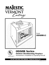
A) Flat on wall B) Cross corner C) **Island
D) *Room divider E) *Flat on wall corner F) Chase installation
Y) 6” minimum
NOTE: (fig. 1)
** Island (C) and Room Divider (D) installation is possible as
long as the horizontal portion of the vent system (X) does not
exceed 20ʼ (610cm). See details in Venting Section.
* When you install your fireplace in(D) Room divider or (E) Flat
on wall corner positions (Y), a minimum of 6” (153mm) clear-
ance must be maintained from the perpendicular wall and the
front side edge of the fireplace.
Refer to (Y) in Figure 1.
IMPORTANT:
PLEASE REVIEW THE FOLLOWING CAREFULLY
Remove any plastic from trim parts before turning the fireplace
ON.
It is normal for fireplaces fabricated of steel to give off some
expansion and/or contraction noises during the start up or cool
down cycle. Similar noises are found with your furnace heat
exchanger or car engine.
It is not unusual for your gas fireplace to give off some odor
the first time it is burned. This is due to the curing of the paint
and any undetected oil from the manufacturing process.
Please ensure that your room is well ventilated - open
all windows.
It is recommended that you burn your fireplace for at least
ten (10) hours the first time you use it. If the optional fan kit
has been installed, place the fan switch in the “OFF” position
during this time.
Locating Your Fireplace
Y
E
A
B
C
D
F
Y
B
X
LU584-R
Locating unit
2/23/01 sta
X
Installation & Operating Instructions
LU584-R
Fig. 1 Locate gas fireplace.
Proposition 65 Warning: Fuels used in gas, wood-
burning or oil fired appliances, and the products of
combustion of such fuels, contain chemicals known to
the State of California to cause cancer, birth defects
and other reproductive harm.
California Health & Safety Code Sec. 25249.6
WARNING: Check with your electronics manufacturer
before installing a television or other electronic de-
vice above this fireplace.
4
LDVR Series Direct Vent Gas Fireplace
10007317
Fireplace Dimensions
F
V - Rough Opening Width
Rough
Opening
Height
Rough
Opening
Depth
S
S
U
T
R
E
I
H
J
D
A
Q
B
K
L
G
M
O
Gas Line
Access
Gas Line
Access
Low
Voltage
Electrical
Access
Electrical
Access
C
Centerline of
7" Collar
M
N
P
Low
Voltage
Access
Fig. 2 Fireplace specifications and framing dimensions.
Ref. 33LDVR 36LDVR 39LDVR 43LDVR
A 33” (838 mm) 36” (914 mm) 39” (991 mm) 43” (1092 mm)
B 28⁷⁄₈ (733 mm) 34¹⁄₄ (870 mm) 34¹⁄₄ (870 mm) 37” (940 mm)
C 31¹⁄₄ (794 mm) 34¹⁄₄ (870 mm) 37¹⁄₄ (946 mm) 41¹⁄₄ (1048 mm)
D 18³⁄₈ (466 mm) 23” (584 mm) 23” (584 mm) 25³⁄₄ (654 mm)
E 24⁷⁄₈ (632 mm) 24” (610 mm) 27” (686 mm) 31” (788 mm)
F 11¹⁄₂ (292 mm) 16” (406 mm) 16” (406 mm) 16” (406 mm)
G 14¹⁄₄ (362 mm) 18³⁄₄ (476 mm) 18³⁄₄ (476 mm) 18³⁄₄ (476 mm)
H 19³⁄₄ (501 mm) 24¹⁄₄ (616 mm) 24¹⁄₄ (616 mm) 27” (686 mm)
I 23¹⁄₄ (590 mm) 27³⁄₄ (705 mm) 27³⁄₄ (705 mm) 30¹⁄₂ (775 mm)
J 4³⁄₄ (121 mm) 5⁵⁄₈ (143 mm) 5⁵⁄₈ (143 mm) 5⁵⁄₈ (143 mm)
K 6⁵⁄₁₆ (160 mm) 8” (203 mm) 8” (203 mm) 8” (203 mm)
L 8⁷⁄₈ (225 mm) 11⁷⁄₈ (302 mm) 11⁷⁄₈ (302 mm) 11⁷⁄₈ (302 mm)
M 2” (51 mm) 2” (51 mm) 2” (51 mm) 2” (51 mm)
N 3³⁄₈ (86 mm) 3¹⁄₄ (83 mm) 3¹⁄₄ (83 mm) 3¹⁄₄ (83 mm)
O 4³⁄₄ (121 mm) 6³⁄₄ (172 mm) 6³⁄₄ (172 mm) 6³⁄₄ (172 mm)
P 6⁵⁄₁₆ (160 mm) 9¹⁄₄ (235 mm) 9¹⁄₄ (235 mm) 9¹⁄₄ (235 mm)
Framing Dimensions
Q 29⁵⁄₈ (753 mm) 35” (889 mm) 35” (889 mm) 37³⁄₄ (959 mm)
R 12” (305 mm) 16¹⁄₂ (419 mm) 16¹⁄₂ (419 mm) 16¹⁄₂ (419 mm)
S 36” (914 mm) 41⁵⁄₈ (1057 mm) 44” (1118 mm) 44¹⁄₈ (1121 mm)
T 51” 1295 mm) 58⁷⁄₈ (1495 mm) 62¹⁄₄ (1581 mm) 62³⁄₈ (1584 mm)
U 25¹⁄₂ (648 mm) 29⁷⁄₈ (748 mm) 31¹⁄₈ (790 mm) 31¹⁄₄ (794 mm)
V 33¹⁄₂ (851 mm) 36¹⁄₂ (927 mm) 39¹⁄₂ (1003 mm) 43¹⁄₂ (1105 mm)
5
LDVR Series Direct Vent Gas Fireplace
10007317
Top of Unit to Ceiling ............................. 36” (914mm)
Appliance
Top ....................................................... 0” (0 mm)
Bottom .................................................. 0” (0 mm)
Side ...................................................... 0” (0 mm)
Back ..................................................... 0” (0 mm)
Venting
Concentric sections of DV Vent
Top, bottom & sides ........................... 1” (25 mm)
Rear Vent Applications:
Top ..................................................... 2” (50 mm)
Sides and Bottom ............................... 1” (25 mm)
A hearth is not mandatory but is recommended for
aesthetic purposes. We recommend a noncombustible
hearth which projects out 12” (305mm) or more from
the front of the fireplace.
Cold climate installation recommendation:
When installing this unit against a
non-insulated exterior wall or chase,
it is mandatory that the outer walls
be insulated to conform to applicable
insulation codes.
Hearth
Mantels
The height that a combustible mantel is fitted above the
fireplace is dependent on the depth of the mantel. This
also applies to the distance between the mantel leg (if
fitted) and the fireplace.
For the correct mounting height and widths refer to
Figs. 3a and 3b, and the following Mantel Charts.
The fitting of a bay window trim kit does not effect
the distances and reference points referred to in the
diagram and chart.
Noncombustible mantels and legs may be installed at
any height and width around the appliance.
When using paint or lacquer to finish the mantel, such
paint or lacquer must be heat resistant to prevent
discoloration.
Clearance to Combustibles
CFM170
J
F
G
H
I
Mantel
Leg
CFM164a
Mantel Leg Chart
06/22/01 sta
Black
Surround
Face
CFM170
DV Builder Front
View
O
N
M
L
K
Side of
Combustion Chamber
CFM164a
Mantel Mantel Leg FromSide
Ref. Leg Depth Ref. of Comb. Opening
F 10” (254mm) K 11¹⁄₂” (292 mm)
G 8” (203mm) L 9¹⁄₂” (241 mm)
H 6” (152mm) M 7¹⁄₂” (191 mm)
I 4” (101mm) N 5¹⁄₂” (140 mm)
J 2” (50mm) O 3¹⁄₂” (89 mm)
Fig. 3b Combustible mantel leg minimum installation.
CFM146
A B C
D
E
V
W
X
Y
Z
Fireplace
CFM146
DV Mantel Chart
7/5/01 sta
Top Louvre As-
sembly
Top of Combustion
Chamber
Mantel Chart
Mantel Shelf Mantel from Top
Ref. or Breast Plate Ref. of Combustion Chamber
Depth 36/39/43 LDVR 33LDVR
V 10” (254 mm) A 17” (432 mm) 16
¹⁄₂” (419 mm)
W 8” (203 mm) B 15” (381 mm) 14
¹⁄₂” (368 mm)
X 6” (152 mm) C 13” (330 mm) 12¹⁄₂” (318 mm)
Y 4” (101 mm) D 11” (279 mm) 10
¹⁄₂” (267 mm)
Z 2” (50 mm) E 9” (229 mm) 8¹⁄₂” (216 mm)
Fig. 3a Combustible mantel minimum installation.
This appliance may be installed in an aftermarket
permanently located, manufactured home or mobile
home, where not prohibited by local codes.
This appliance is only for use with the type of gas indicated
on the rating plate. This appliance is not convertible for
use with other gases, unless a certified kit is used.
The LDVR has been approved for mobile home
installations.
6
LDVR Series Direct Vent Gas Fireplace
10007317
Max. Min.
Input Input
Model Fuel Gas Control BTU/h BTU/h
33LDVRRN Nat Millivolt 16,000 11,200
33LDVRRP Prop Millivolt 16,000 12,000
33LDVREN Nat 24V Hi/Lo 16,000 11,200
33LDVREP Prop* 24V Hi/Lo 16,000 12,000
36LDVRRN Nat Millivolt 19,500 13,650
36LDVRRP Prop Millivolt 19,500 14,625
36LDVREN Nat 24V Hi/Lo 19,500 13,650
36LDVREP Prop* 24V Hi/Lo 19,500 14,625
39LDVRRN Nat Millivolt 23,000 16,100
39LDVRRP Prop* Millivolt 22,500 16,875
39LDVREN Nat 24V Hi/Lo 23,000 16,100
39LDVREP Prop* 24V Hi/Lo 22,500 16,875
43LDVRRN Nat Millivolt 26,000 18,200
43LDVRRP Prop* Millivolt 24,000 18,000
43LDVREN Nat 24V Hi/Lo 26,000 18,200
43LDVREP Prop* 24V Hi/Lo 24,000 18,000
Noncombustible materials such as brick or tile may be
extended over the edges of the face of the fireplace.
DO NOT cover any vent or grille panels.
If a Trim Kit is going to be installed on the fireplace, the
brick or tile will have to be installed flush with the edges
of the fireplace.
Final Finishing
Gas Specifications
33LDVR / 36LDVR / 39LDVR / 43LDVR
Certified To
ANSI Z21.88b-2003 / CSA 2.33b-2003
Vented Gas Fireplace Heaters
Framing and Finishing
Inlet Minimum 5.5” w.c. 11.0” w.c.
Inlet Maximum 14.0” w.c. 14.0” w.c.
Manifold Pressure 3.5” w.c. 10.0” w.c.
Gas Inlet and Manifold Pressures
Natural LP (Propane)
High Elevations
Input ratings are shown in BTU per hour and are
certified without deration for elevations up to
4,500 feet (1,370m) above sea level.
For elevations above 4,500 feet (1,370m) in USA,
installations must be in accordance with the cur-
rent ANSI Z223.1/NFPA 54 and/or local codes hav-
ing jurisdiction.
In Canada, please consult provincial and/or local
authorities having jurisdiction for installations at
elevations above 4,500 feet (1,370m).
Check fireplace to make sure it is levelled
and properly positioned.
To mount the appliance:
1. Choose the location.
2. This unit comes with four (4) flanges pre-mounted
on both sides of the fireplace to allow two different
drywall thicknesses to be used. Flange “A” is for
1/2” drywall while flange “B” is for 5/8” drywall.
3. Bend the desired flanges out 90° on both sides of
the fireplace. Slide the fireplace into the framed
opening until the flanges contact the front surfaces
of the framing. Level the unit and secure it firmly in
place.
Fig. 4 Nailing flanges.
Flange Drywall
Position Depth
A 1/2” / 13 mm
B 5/8” / 16 mm
Flange Location for
Desired Drywall Depth
FP1539
A
B
33LDVR units: GFRN2I0, GFRL2I0, GFRE2I0
36LDVR units: GFRN2J0, GFRL2J0, GFRE2J0
39LDVR units: GFRN2K0, GFRE2K0
43LDVR units: GFRN2N0, GFRE2N0
*Using conversion kit
7
LDVR Series Direct Vent Gas Fireplace
10007317
Installation
1. Thread the wiring through the holes on the end
panels of the fireplace. Take care not to cut the wire
or insulation on metal edges. Route the wire to a
conveniently located receptacle box.
2. Attach the wire to the ON/OFF switch and install the
switch into the receptacle box.
3. Connect the other ends of the wire to the gas control
valve. (Fig. 6)
The gas pipeline can be brought in through the rear
of the appliance as well as the bottom. Knockouts are
provided on the bottom behind the valve to allow for the
gas pipe installation and testing of any gas connection.
It is most convenient to bring the gas line in from the
rear right side of the valve as this allows fan installation
or removal without disconnecting the gas line.
The gas line connection can be made with properly
tinned 3/8” copper tubing, 3/8” rigid pipe or an ap-
proved flex connector. Since some municipalities have
additional local codes, it is always best to consult your
local authority and the National Fuel Gas Code, ANSI
Z223.1/NFPA 54 in the USA or the CSA-B149.1 instal-
lation code.
Do not wire the remote ON/OFF wall switch
for the gas fireplace to the 120 volt power
supply.
Alternate Switch Location
The remote switch can be installed on the front/side
of the access door. Simply mount the switch to the
bracket provided and screw the bracket to either side
of the frame, lining up the screws with the pre-punched
holes. (Fig. 7)
The gas control is equipped with a captured screw type
pressure test point, therefore it is not necessary to pro-
vide a 1/8” test point up stream of the control.
When using copper or flex connector use only approved
fittings. Always provide a union when using black iron
pipe so the gas line can be easily disconnected for
burner or fan servicing. See gas specification for pres-
sure details and ratings.
The fireplace valve must not be subjected to any test
pressures exceeding 1/2 psi. Isolate or disconnect this
and any other gas appliance control from the gas line
when pressure testing.
Gas Line Installation Remote ON/OFF Switch
When purging the gas lines, the front win-
dow frame assembly must be removed.
Always check for gas leaks with a mild
soap and water solution. Do not use an
open flame for leak testing.
FP297A
INSTA VENT FREE
UVHB26 GAS SUPPLY
7/1/98
FP297A
1/2” Gas Supply
1/2” NPT x 1/2” Flare Shut-
off Valve
3/8” Flex Line
(From Valve)
Fig. 5 Typical gas supply installation.
FP1024
alternate
remote switch
location
1/27/00 djt
FP1024
Fig. 7 Alternate switch location.
TP
TH
TP
TH
FP1224
Remote switch
11/02
Remote ON/OFF Switch
or Thermostat
or Remote Control
Gas
Control
Valve
FP1224
Fig. 6 Remote switch wiring diagram.
8
LDVR Series Direct Vent Gas Fireplace
10007317
The fireplace, when installed, must be
electrically connected and grounded in
accordance with local codes or, in the ab-
sence of local codes, with the current CSA
C22.1 Canadian Electrical Code.
For USA installations follow local codes
and the national electrical code ANSI/
NFPA No. 70.
It is strongly suggested that the wiring of
the EB-1 Electrical Junction Box be carried
out by a licensed electrician.
Ensure that the power to the supply line
has been disconnected before commenc-
ing this procedure.
The EB-1 Electrical junction box has been fitted stand
-
ard on this model to allow for the easy connection of an
optional fan kit.
To connect the EB-1 box to the house electrical supply
follow the steps below.
1. Unscrew the retaining screw from the EB-1 base
plate and remove the EB-1 assembly from the
appliance. (Fig. 8)
2. Remove the front cover of the EB-1 box.
3. Remove the plug socket assembly from the EB-1
box.
4. Feed the supply line in through the EB-1 opening in
the side of the appliance and then through the back
of the EB-1 assembly. (Fig. 8)
5. Connect the black wire of the power supply line to
the brass screw (polarized) of the socket assembly.
6. Connect the white wire of the power line to the
chrome screw of the socket assembly.
7. Connect the ground wire of the supply line to the
green screw of the socket assembly.
8. Refit the socket assembly back into the electrical
box and replace the cover plate. Secure the cable
with the clamp on the outside of the EB-1 base
plate and refit the EB-1 assembly to the unit with the
screw removed in step 1.
This appliance may be fitted with a Synetek ignition
module.
Installation of the remote on/off starter switch or
wall thermostat on electronic ignition units.
1. Thread the wiring through the holes on the side
panels of the appliance. Take care not to cut the wire
or insulation on metal edges. Route the wire to a
conveniently located receptacle box.
2. Attach the wire to the ON/OFF switch and install the
switch into the receptacle box.
3. Connect the white wire from the wall switch or wall
thermostat to the white wire terminal from the elec-
tronic module. Connect the black wire from the wall
switch or the red wire from the wall thermostat, to
the red wire terminal from the electronic module.
Electronic Gas Control Valve
EB-1 Electrical Box
FP580
INSTA VENT FREE
EB1 JUNCTION BOX
11/18/97
OUTSIDE

INSIDE
BACK OF UNIT
FP580
Electrical Box
Retaining Screw
Fig. 8 EB-1 receptacle.
9
LDVR Series Direct Vent Gas Fireplace
10007317
Your fireplace is approved to be vented either through
the side wall, or vertically through the roof.
Only CFM Corporation venting components specifi-
cally approved and labelled for this fireplace may be
used.
Vent terminations shall not be recessed into a wall or
siding.
Horizontal venting which incorporates the twist lock
pipe must be installed on a level plane without an
inclining or declining slope.
Horizontal venting which incorporates the use of flex
venting shall have an inclining slope from the unit of
1” (25 mm) per 24” (610 mm).
General Venting
There must not be any obstruction such as bushes,
garden sheds, fences, decks or utility buildings within
24” (610mm) from the front of the termination hood.
Do not locate termination hood where excessive snow
or ice build up may occur. Be sure to check vent termi-
nation area after snow falls, and clear to prevent ac-
cidental blockage of venting system. When using snow
blowers, make sure snow is not directed towards vent
termination area.
Location of Vent Termination
It is imperative the vent termination be located observ-
ing the minimum clearances as shown on the next
page.
*Check with local codes or in absence of same with
CSAB149.1 Installation Codes (1991) for Canada or fol-
low the current National Fuel Gas Code, ANSI Z223.1/
NFPA 54 for installations in the USA.
POWER CORD
CIRCUIT BOARD
ON/OFF SWITCH
OR
WALL THERMOSTAT
VALVE
RED
WHITE
BLUE
YELLOW
PURPLE
BLACK
WHITE
GREEN
PILOT SENSING
PILOT IGNITER
ORANGE
L1
L2
M
O
P
O
FP1571
SIT822
Synetek wiring
4/05
CLEAR
Fig. 9 SIT822 Valve with Synetek electronic control wiring diagram.
FP1571
10
LDVR Series Direct Vent Gas Fireplace
10007317
V
V
V
V
V
V
V
X
X
X
D
E
B
B
B
C
B
M
B
A
J
K
F
L
VENT TERMINATION AIR SUPPLY INLET
AREA WHERE TERMINAL IS NOT PERMITTED
H
I








V
B
CFM145a
DV Termin Location
5/01/01 Rev. 12/05/01
sta
INSIDE
CORNER DETAIL
V
A
G
V
N
N
V
V
G
G
A
CFM145a
General Venting Information - Termination Location
A = Clearance above grade, veranda, porch, 12” (30cm) 12” (30cm)
deck, or balcony
B = Clearance to window or door that may be 6” (15cm) for appliances 6” (15cm) for appliances
opened < 10,000Btuh (3kW), 12” (30cm) < 10,000 Btuh (3kW), 9”
for appliances > 10,000 Btuh (3kW) and (23cm) for appliances > 10,000
< 100,000 Btuh (30kW), 36” (91cm) Btuh (3kW) and < 50,000 Btuh
for appliances > 100,000 Btuh (30kW) (15kW), 12” (30cm) for
appliances > 50,000 Btuh (15kW)
C = Clearance to permanently closed window 12” (305mm) recommended to 12” (305mm) recommended to
prevent window condensation prevent window condensation
D = Vertical clearance to ventilated soffit located
above the terminal within a horizontal 18” (458mm) 18” (458mm)
distance of 2ʼ (610mm) from the center
line of the terminal
E = Clearance to unventilated soffit 12” (305mm) 12” (305mm)
F = Clearance to outside corner see next page see next page
G = Clearance to inside corner (see next page) see next page see next page
H = Clearance to each inside of center line (91cm) within a height of 15ʼ (5m) (91cm) within a height of 15ʼ
extended above meter/regulator assembly above the meter/regulator assembly (5m) above the meter/regulator
assy
I = Clearance to service regulator vent outlet 3ʼ (91cm) 3ʼ (91cm)
J = Clearance to nonmechanical air supply inlet 6” (15cm) for appliances < 10,000 6” (15cm) for appliances
to building or the combustion air inlet to any Btuh (3kW), 12” (30cm) for < 10,000 Btuh (3kW), 9”
other appliances appliances > 10,000 Btuh (3kW) and (23cm) for appliances > 10,000
< 100,000 Btuh (30kW), 36” (91cm) Btuh (3kW) and < 50,000 Btuh
for appliances > 100,000 Btuh (30kW) (15kW), 12” (30cm) for
appliances > 50,000 Btuh (15kW)
K = Clearance to a mechanical air supply inlet (1.83m) (91cm) above if within 10
feet (3m) horizontally
L = Clearance above paved sidewalk or paved (2.13m)† (2.13m)†
driveway located on public property
M = Clearance under veranda, porch, deck or 12” (30cm)‡ 12” (30cm)‡
balcony
N = Clearance above a roof shall extend a minimum of 24” (610mm) above the highest point when it passes through the roof
surface, and any other obstruction within a horizontal distance of 18” (450mm).
1 In accordance with the current CSA-B149 Installation Codes
2 In accordance with the current ANSI Z223.1/NFPA 54 National Fuel Gas Codes
A vent shall not terminate directly above a sidewalk or paved driveway which is located between two single family dwellings and
serves both dwellings
‡ only permitted if veranda, porch, deck or balcony is fully open on a minimum 2 sides beneath the floor:
NOTE: 1. Local codes or regulations may require different clearances.
2. The special venting system used on Direct Vent Stoves are certified as part of the appliance, with clearances tested and
approved by the listing agency.
Canadian Installations
1
US Installations
2
11
LDVR Series Direct Vent Gas Fireplace
10007317
Outside Corner
Inside Corner
Termination Clearances
Termination clearances for buildings with combustible and noncombustible exteriors.
A =
Combustible
6"(152mm)
Noncombustible
2"(50mm)
B =
Combustible
6"(152mm)
Noncombustible
2"(50mm)
A
Balcony -
with no side wall
G =
Combustible &
Noncombustible
12"(305mm)
G
Balcony -
with perpendicular side wall
H = 24"(610mm)
J = 20"(508mm)
H
J
B
Recessed Location
C = Maximum depth of 48"
(1219mm) for recessed
location.
D = Minimum width for back wall
of a recessed location.
Combustible 38"(965mm)
Noncombustible 24"(610mm)
E = Clearance from corner in
recessed location.
Combustible 6"(152mm)
Noncombustible 2"(50mm)
C
D
C
E
V
V
Combustible &
Noncombustible
V
V
V
General Information Assembling Vent Pipes
Canadian Installations:
Venting system must be installed in accordance with the
current CSA-B149.1 installation code.
USA Installations:
The venting system must conform with local codes and/
or the current National Fuel Gas code ANSI Z223.1/
NFPA 54.
Only venting components manufactured by CFM Corpo
-
ration can be used in Direct Vent systems.
Flex Vent Pipes
Before joining the flex vent pipe to the unit, apply a
bead of high temperature sealant* (provided) to the 4”
pipe exiting the fireplace. Secure flex vent piep in place
with a hose clamp (provided).
*Be sure the flex pipe overlaps at least 1” (25mm) onto
the collars of the fireplace and termination. If the ter
-
mination has an internal bead, be sure to overlap and
secure 1” (25mm) past the bead.
584-15
Fig. 10 Termination clearances.
* Be sure the vent is actually crushed before proceed-
ing. Apply a tug to be sure the vent will not slip off the
collars.
Repeat process with 7” flex vent pipe. The same proce-
dure must be performed on the vent side.
FP1471
flex vent
Apply High Temperature
Sealant
Hose Clamp
FP1471
Fig. 11 Apply high temperature sealant to 4” and 7” pipes.
12
LDVR Series Direct Vent Gas Fireplace
10007317
The vent chart should be read in conjunction with the
following vent installation instructions to determine the
relationship of the vertical and horizontal dimensions of
the vent system.
1. Determine the height of the center of the horizontal
vent pipe exiting through the outer wall. Using this
dimension on the Sidewall Vent Graph (Fig. 13)
locate the point intersecting with slanted graph line.
2. From the point of this intersection, draw a vertical
line to the bottom of the graph.
3. Select the indicated dimension, and position the
fireplace in accordance with same.
Example A:
If the vertical dimension from the floor of the
fireplace is 1 (3.4m) the horizontal run to the face
of the outer wall must not exceed 14ʼ (4.3m).
Example B:
If the vertical dimension from the floor of the unit is
(2.14m), the horizontal run to the face of the outer
wall must not exceed 8¹⁄₂ʼ (2.6m).
How to Use the Vent Graph
Rear Wall Venting Applications
When installed as a rear vent unit this appliance may
be vented directly to a termination located on the rear
wall behind the appliance.
Only CFM Corporation venting components are
approved to be used in these applications. (Refer to
“Venting Components” listed for different installation
requirements)
The maximum horizontal distance between the rear
of the appliance (or end of the transition elbow in a
corner application) and the outside face of the rear
wall is 20” (508mm). (Fig. 14)
Only one 45° elbow is allowed in these installations.
Minimum clearances between vent pipe and com-
bustible materials are as follows:
Top - 2” (50mm)
Sides - 1” (25mm)
Bottom - 1” (25mm)
Horizontal dimension from the outside face of the
wall to the center of the fireplace vent flange
Sidewall vent graph showing the relationship between vertical
and horizontal dimensions for a Direct Vent flue system.
Vertical dimension from the floor of the unit
to the center of the horizontal vent pipe
3
4
5
6
7
8
9
10
11
12
13
14
15
16
17
18
19
20
21
22
23
24
25
26
27
28
29
30
3 4 5 6 7 8 9 10 11 12 13 14 15 16 17 18 19 20
eg: A
eg: B
CFM102
DV Graphic
9/28/00 sta
Fig. 13 Sidewall venting graph. (Dimensions in feet)
TWL100
Twist Lock Pipe
3/12/99 djt
Male End Female End
Screw Holes
TWL100
Fig. 12 Twist-lock pipe joints.
Twist Lock Pipes
When using CFM Corporation twist-lock pipe it is not
necessary to use sealant on the joints. The only areas
of the venting system that need to be sealed with high
temperature silicone sealant are the collars on the
fireplace and termination, and the sliding joint of any
telescopic vent section used in the system.
To join the twist lock pipes together, simply align the
beads of the male end with the grooves of the female
end, then while bringing the pipe together, twist the pipe
until the flange on the female end contacts the external
flange on the male end. It is recommended that you
secure the joints with three (3) sheet metal screws,
however this is not mandatory with twist lock pipe.
To make it easier to assemble the joints we suggest
putting a lubricant (Vaseline or similar) on the male end
of the twist lock pipe prior to assembly.
13
LDVR Series Direct Vent Gas Fireplace
10007317
DVR584-600
Rear vent no elbows
2/99 djt
20"
(508mm)
Top View
Straight Venting
FP836
Rear Vent-Top View
11/21/98
20"
(508mm )
Max.
RE AR V EN T-TOP V IE W
20"
(508mm )
Max.
Top View
Rear Vent Corner Installation
Fig. 14 Rear vent applications, one 45° elbow.
45°
45°
Rear Wall Installation
Twist Lock Pipe
STEP 1
Locate vent opening on the wall. To locate hole center
consult with appropriate fireplace dimensions, Page 4.
Frame as shown below.
NOTE: When using flex vent, the opening will have to
be measured according to the 1/2” (13 mm) rise in 12”
(305 mm) vertical run.
Combustible Walls
(Fig. 15): Cut a 10³⁄₈”H x 9³⁄₈” W
(264 x 240mm) hole through the exterior wall and frame
as shown.
Noncombustible Walls
(Fig. 15): Hole opening must
be 7¹⁄₂” (190mm) in diameter.
STEP 2
Measure wall thickness and cut zero clearance sleeve
parts to proper length (MAXIMUM 12”/305mm). Assem
-
ble sleeve and attach to firestop with #8 sheet metal
screws (supplied). (Fig. 16)
VO584-100
Vent Opening
2/99 djt
Vent Opening for Combustible Wall
9³⁄₈
(240mm)
10³⁄₈
(264mm)
Fireplace Hearth
Framing
Detail
Opening for Noncombustible Wall
7¹⁄₂
(190mm)
VO584-100
Fig. 15 Locate vent opening on wall.
ZCS101
Zero Clearance Sleeve
3/11/99 djt
Max. Length
12” (305mm)
#8 Screws (2)
#8 Screws
(2)
Adjustable
Zero Clearance
Sleeve
#8
Screws
(2)
Adjustable Zero Clearance Sleeve
ZCS101
Fig. 16 Adjustable zero clearance sleeve.
Firestop
STEP 3
Measure from the fireplace collar or elbow face to face
of outside wall (add 2” for vent pipe overlap). Mark
pipes and cut to length. It is very important that the two
pipes are flush with the outside wall once the fireplace
is in its final location. (Fig. 17)
STEP 4
Slip 4” and 7” pipes onto respective flue collars. Make
sure to fix to the fireplace collar the 4” pipe with three
(3) screws before fixing the 7” pipe on the 7” collar.
Both pipes must be on a level plane. (Fig 18)
STEP 5
Guide the vent termination 4” collar into the 4” pipe then
the 7” collar into the 7” pipe. Do not force the venting
into position. If the pipes do not line up with the termi-
nation collars, disassemble pipes and reattach to the
fireplace collar. (Fig. 18)
STEP 6
Secure fireplace to floor through floor holes and adjust
-
able frame drywall strip (nailing flange) to frame. (Refer
to Framing & Finishing Section).
14
LDVR Series Direct Vent Gas Fireplace
10007317
CFM133
DVR Series Typical corner install
2/26/01 sta
Zero
Clearance
Sleev
e
Firestop
CFM133
Fig. 17 Firestop and zero clearance sleeve in place.
FP1005
Side View Vent Termination
1/25/00 djt
Finished Wall
Vent Termi-
nation
FP1005
Fig. 18 Side view of final unit location.
Vertical Sidewall Applications
Since it is very important that the vent-
ing system maintain its balance between
the combustion air intake and the flue
gas exhaust, certain limitations as to vent
configurations apply and must be strictly
adhered to.
The Vent Graph shows the relationship between vertical
and horizontal side wall venting and will help to deter-
mine the various dimensions allowable.
Minimum clearance between vent pipes
and combustible materials is 1”(25mm) on
top, bottom and sides unless otherwise
noted.
When vent termination exits through foundations less
than 20” below siding outcrop, the vent pipe must
flush up with the siding. It is always best to locate the
fireplace in such a way that minimizes the number of
offsets and horizontal vent length.
The horizontal vent run refers to the total length of vent
pipe from the flue collar of the fireplace to the face of
the outer wall.
Rear Wall Vent Installations -
Flex Vent Pipe
Follow Steps 1 and 2 on Page 13.
Step 3
Install the 4” (102mm) flex vent pipe to the appliance
collars described in “General Information Assembling
Vent Pipes”, Page 11. If the installation requires a 45°
angle, grasp the vent pipe close to the appliance collar
and bend to 45°. DO NOT exceed 45°. (Fig. 19)
Install the 7” vent pipe in the same manner as Step 2.
NOTE: There must be a 1” (25mm) rise in a 24”
(610mm) length of flex vent.
Step 4
Assemble the flex vent to the collars on the termination
as you did on the appliance.
FP1473
corner flex install
4/04 djt
Termination
Flex Section
Appliance Collars
FP1473
Fig. 19 Grasp the vent pipe close to the collar and bend to
45° angle. Do not exceed 45°.
FP1472
rise in length
4/04 djt
FP1472
Fig. 20 There must be a 1/2” rise per foot length.
Rise
15
LDVR Series Direct Vent Gas Fireplace
10007317
•IMPORTANT• Minimum clearance between vent
pipes and
combustible materials is one (1”) inch (25 mm)
on bottom, sides and top.
Twist Lock Vent Starter Kit 7TDVSK, plus
Transition Elbow 7TDVRT90 must be used
in Vertical Sidewall installations. The 4”
pipe must be centered inside the 7” pipe
coming off the transition elbow.
Canadian & USA Installations:
The venting system must conform with local codes, or
in the absence of local codes, with National Fuel Gas
Code, ANSI Z223.1/NFPA 54 - latest edition, or CSA
B149.1 Installation Code.
Only CFM Corporation venting components specifically
approved and labelled for this fireplace may be used
.
Maximum
3' (914mm)
7TDVRT90
Elbow
CFM142
Ve nting
2/2/01 s ta
CFM142
Fig. 22 Maximum horizontal vent run.
18” (45cm). This does not apply if the 45° elbows
are installed on the vertical part of the vent system.
The maximum number of elbow degrees in a system
is 270°. (Fig. 24)
Example: According to the chart the maximum hori-
zontal vent length in a system with a 7.5ʼ (2.3m) ver-
tical rise is 20ʼ (6 m) and if a 90° elbow is required in
the horizontal vent it must be reduced to 17ʼ (5.2 m).
In Figure 23 Dimension A plus B must not be greater
than 17ʼ (5.2 m).
The maximum number of 45° elbows permitted per
side wall installation is two (2). These elbows can be
installed in either the vertical or horizontal run.
For each 45° elbow installed in the horizontal run,
the length of the horizontal run MUST be reduced by
V584-201
Horizontal Run
2/99 djt
10 ft.
(3048 mm)
7 ft. 6 in.
(2286 mm)
7 ft.
(2134 mm)
CFM147
Fig. 23 Maximum vent run with elbows.
90° Elbow = 3 ft.
A + B = 17 ft. (Max.)
CFM14 1
2/2/0 1 st a
Maximum
20 ft. (6.1m)
7.5'
(2.3m)
7TDVRT90
Elbow
15 ft.
(4572mm)
48"
(1.2m)
12"
(305mm)
Vertical Dimension
7¹⁄₂ʼ Minimum When
Horizontal Run is
20ʼ
CFM141
Fig. 21 Maximum number of 90° elbows is three (3).
Horizontal plane means no vertical rise exists on this
portion of the vent assembly.
The maximum horizontal vent run is 20 ft. (6.1m)
when the vertical vent rise is 7¹⁄₂ ft. (2.3m). (Fig. 21)
The maximum number of 90° elbows per side wall
installation is three (3).
If a 90° elbow is used in the horizontal vent run
(level height maintained) the maximum horizontal
vent length is reduced by 36” (914 mm). (Fig. 22)
This does not apply if the 90° elbows are used to
increase or redirect a vertical rise. (Fig. 23)
1
2
3
4
1 + 2 + 3 + 4 = 270
o
CFM132
Insert Rear Vent Sidewall
2/26/01 sta
CFM132
Fig. 24 Maximum number of elbows.
Example:
Elbow 1 = 90˚
Elbow 2 = 45˚
Elbow 3 = 45˚
Elbow 4 = 90˚
Total angular variation = 270˚
16
LDVR Series Direct Vent Gas Fireplace
10007317
Vertical Sidewall Installation
STEP 1
Locate vent opening on the wall. It may be necessary
to first position the fireplace and measure to obtain hole
location. Depending on whether the wall is combustible
or noncombustible, cut opening to size. (Fig. 25)
For combustible walls first frame in opening.
Combustible Walls
(Fig. 25): Cut a 9³⁄₈”H x 9³⁄₈” W
(240 x 240mm) hole through the exterior wall and
frame.
Noncombustible Walls (Fig. 25): Hole opening must
be 7.5” (190mm) in diameter.
VO584-100
Vent Opening
2/99 djt
Vent Opening for Combustible Wall
9³⁄₈
(240mm)
9³⁄₈
(240mm)
Fireplace Hearth
Framing Detail
Opening for Noncombustible Wall
7¹⁄₂
(190mm)
VO584-100
Fig. 25 Locate vent opening on wall.
STEP 2
Measure wall thickness and cut adjustable zero
clearance sleeve parts to proper length (MAXIMUM
12”/305mm). (Fig. 26) Adjust sleeve to minimum (9³⁄₈” x
9³⁄₈” and attach to firestop with #8 sheet metal screws
(supplied). Assemble sleeve and attach to firestop with
#8 sheet metal screws (supplied). Install firestop as-
sembly.
Zero clearance sleeve is only required for
combustible walls.
STEP 3
Apply a bead of high temperature sealant to the inner
and outer flue collars of the fireplace and using ap-
propriate venting component(s) attach to fireplace with
three (3) screws. (Fig. 27) Follow with the installation
of the inner and outer elbow. Again secure joints with
three (3) sheet metal screws. Wipe off any excess high
temperature sealant.
CFM135
Zero Clearance Sleeve
2/26/01 sta
Adjustable Zero Clear-
ance Sleeve
Maximum Length
12” (305mm)
#8 Screws (2)
Adjust-
able Zero
Clearance
Sleeve
Firestop
#8 Screws
(2)
Wall Exterior
Wood Framing
Firestop
Vent Pipe
Drywall
Zero Clearance
Sleeve Flush with
Wall Exterior
CFM135
Fig. 26 Locate vent opening on wall.
#8 Screws (2)
STEP 4
Measure the horizontal length requirement including a
2” (50mm) overlap, i.e. from the elbow to the outside
wall finish plus 2”, or the distance required if installing a
second 90° elbow. (Fig. 28)
STEP 5
Use appropriate length of pipe section - telescopic or
fixed - and install the horizontal vent sections. The 20”
(508mm) section of pipe which goes through the wall is
packaged with the 7TDVSK starter kit, and can be cut
to suit if necessary. (Fig. 29)
Sealing vent pipe and firestop gaps with
high temperature sealant will restrict cold
air being drawn in around fireplace.

CFM143
2/2/01 sta
Ensure Pipes are
Concentric
Bead of Seal-
ant
(If necessary)
CFM143
Fig. 27 Apply sealant to inner and outer pipe.
17
LDVR Series Direct Vent Gas Fireplace
10007317
STEP 6
Apply high temperature sealant to 4” (102 mm) and 7”
(178 mm) collars or the termination one inch away from
the end. Guide the vent terminationʼs 4” and 7”
collars
into their respective vent pipes. Double check that the
vent pipes overlap the collars by 2” (50 mm). Secure the
termination to the wall with screws provided and caulk
around the wall plate to weatherproof. (Fig. 30)
STEP 7
Support the horizontal pipes every 36” (914 mm) with
metal pipe straps. Make sure that the horizontal vent
pipe is installed on a level horizontal plane.
STEP 8
Re-check the fireplace to make sure that it is levelled,
properly positioned, and nailed or screwed to the floor.
If applied, the fireplaces adjustable frame drywall strips
(nailing flanges) should be fastened. Refer to “Framing
& Finishing”.
CFM137
Rear Vent length
2/26/01 sta
X
High
Temperature Sealant
CFM137
Fig. 29 Apply high temperature sealant.
CFM138
4", 7" collar
2/26/01 sta
X
X
CFM138
Fig. 30 Horizontal length requirement.
CFM136
Rear Vent horizontal length
2/26/01 sta
X
Always install hori-
zontal venting on a
level plane.
CFM136
Fig. 28 Measure horizontal length including 2” overlap.
Below Grade Installations
When it is not possible to meet the required vent ter-
minal clearances of 12” (305mm) above grade level a
snorkel vent kit #7TDVSNORK is required. It allows
installation depth of down to 7” (178 mm) below grade
level. The 7” is measured from the center of the hori-
zontal vent pipe as it penetrates through the wall.
If venting system is installed below
ground, we recommend a window well with
adequate and proper drainage.
Ensure sidewall venting clearances are observed.
The maximum horizontal run with 24”
vertical rise is 36” (914 mm) from the
back of the fireplace to the face of the
exterior wall. See vent graph (Page 12) for
extended horizontal run if the vertical rise
exceeds 24” (610 mm).
1. Establish vent hole through the wall. (Fig. 25)
2. Remove soil to a depth of approximately 16”
(406mm) below base of snorkel. Install window
well (not supplied). Refill hole with 12” (305 mm) of
coarse gravel leaving a clearance of approximately
4” (102 mm) below snorkel. (Fig. 31)
3. Install vent system. See Page 13, Steps 2 through 5.
4. Ensure a watertight seal is made around the vent
pipe coming through the wall.
5. Apply high temperature sealant caulking (supplied)
around the 4” and 7” snorkel collars.
6. Slide into the vent pipe and secure to the wall.
7. Level the soil to maintain a 4” (102 mm) clearance
below snorkel. (Fig. 31)
18
LDVR Series Direct Vent Gas Fireplace
10007317
Do not back fill around snorkel. A
clearance of at least 4” (102mm) must be
maintained between the snorkel and the
soil.
BG401
Snorkel
2/10/99 djt
Foundation Recess
Snorkel
Wall Screws
Recess Brackets
Watertight Seal
Around Pipe
Sheet Metal
Screws
BG401
Fig. 32 Snorkel installation, recessed foundation.
BG400
Below grade installation
2/10/99 djt
10/19/99 added standoffs
24" (610mm)
Minimum*
Zero Clearance
Sleeve
(if required)
Firestop
7” Pipe
7TDVSNORK
(Snorkel)
4” (102mm)
Clearance
Min.
Window
Well
Gravel
Drain
Foundation Wall
BG400
Fig. 31 Below grade installation.
*A minimum of 24” (608mm)
vertical pipe must be installed
when using 7TDVSNORK Kit.
If the foundation is recessed, use recess brackets (not
supplied) for securing lower portion of the snorkel.
Fasten brackets to wall first, then secure to snorkel
with self drilling #8 x 1/2 sheet metal screws. It will be
necessary to extend vent pipes out as far as protruding
wall face. (Fig. 32)
This Gas Fireplace has been approved for:
1. Vertical installations up to 40ʼ (12 m) in height. Up to
10ʼ (3 m) horizontal vent run can be installed within
the vent system using a maximum of three 90°
elbows.
Vertical Through-the-Roof Applications
CFM148
Maximum
10ʼ
(3 m)
Minimum
(2.4 m) /
Maximum
40ʼ (12 m) Vertical
Rise
CFM148
Pipe Straps Every
(914 mm)
Fig. 33 Support straps for horizontal runs.
This Gas Fireplace has been approved for:
1. Vertical installations up to 40ʼ (12 m) in height. Up to
10ʼ (3 m) horizontal vent run can be installed within
the vent system using a maximum of three 90°
elbows.
2. Up to two 45° elbows may be used within the
horizontal run. For each 45° elbow used on the
horizontal level the maximum horizontal length must
be reduced by 18” (457 mm).
Example: Maximum horizontal length
0 x 45° elbows = 10ʼ (3 m)
1 x 45° elbows = 8
¹⁄₂ʼ (2.6 m)
2 x 45° elbows = (2.1 m)
3. A minimum of an 8ʼ vertical rise.
4. Two sets of 45° elbows offsets within these vertical
installations. From 0 to a maximum of 8ʼ (2.4 m) of
vent pipe can be used between elbows. (Fig. 34)
5. 7DVCS must be used to support offsets. (Fig. 34)
This application will require that you first determine
the roof pitch and use the appropriate 7DVSKV (A, B
or F). (Refer to Venting Components List, Page 21)
19
LDVR Series Direct Vent Gas Fireplace
10007317
Vertical Through-the-Roof Installation
CFM100
Firestop-Vertical
09/20/00
11"
11"
Joist
Joist
Firestop Spacer
Nails (4)
Upper Floor
Attic Insulation
Shield
Ceiling Instal-
lation
CFM100
Fig. 35 Place firestop spacer(s) and secure.
FP1021
Typical vertical
through the roof
application
3/26/00 djt
Max.
(2.4m)
45°
Max.
(2.4m)
45°
40ʼ
(12m)
Typical
Ceiling
Support
Application
Typical Roof
Support Ap
-
plication
FP1021
Typical Offset Installation
Fig. 34 Typical vertical roof applications.
1. Locate your fireplace.
2. Plumb to center of the (4”) flue collar from ceiling
above and mark position.
3. Cut opening equal to 9
³⁄₈” x 9³⁄₈” (240 x 240mm).
4. Proceed to plumb for additional openings through
the roof. In all cases, the opening must provide a
minimum of 1 inch clearance to the vent pipe, i.e.,
the hole must be at least 9³⁄₈” x 9³⁄₈” (240 x 240mm).
5. Place fireplace into position.
6. Place firestop(s) #7DVFS or Attic Insulation Shield
#7DVAIS into position and secure. (Fig. 35)
7. Install roof support (Fig. 36 & 37) and roof flashing
making sure upper flange is below the shingles. (Fig.
36)
8. Install appropriate pipe sections until the venting is
above the flashing. (Fig. 36)
9. Install storm collar and seal around the pipe.
10. Add additional vent lengths for proper height. (Fig
38)
11. Apply high temperature sealant to 4” and 7” collars
of vertical vent termination and install.
If there is room above ceiling level,
firestop spacer must be installed on both
the bottom and the top side of the ceiling
joists. If an attic is above ceiling level a
7DVAIS (Attic Insulation Shield) must be
installed. (Fig. 35)
The enlarged ends of the vent section
always face downward. (Fig. 36)
TWL101a
Twist Lock Pipe
2/8/99 djt
3 #5 Sheet Metal
Screws per Joint
Storm Collar
TWL101a
Fig. 36 Roof flashing.
Sealant
20
LDVR Series Direct Vent Gas Fireplace
10007317
FP1022
Typical Straight Up Installation
1/26/00 djt
40ʼ
(12m)
Storm Collar
Roof Flash-
ing
Vent
Termination
Roof
Min.
Roof Support
Attic Insulation
Shield
Attic
Insulation
Joists
Joists
FP1022
Fig. 37 Typical straight-up installation.
Min.
2' (610 mm)
FP1185
Fig. 38 Minimum termination to roof clearance.
  • Page 1 1
  • Page 2 2
  • Page 3 3
  • Page 4 4
  • Page 5 5
  • Page 6 6
  • Page 7 7
  • Page 8 8
  • Page 9 9
  • Page 10 10
  • Page 11 11
  • Page 12 12
  • Page 13 13
  • Page 14 14
  • Page 15 15
  • Page 16 16
  • Page 17 17
  • Page 18 18
  • Page 19 19
  • Page 20 20
  • Page 21 21
  • Page 22 22
  • Page 23 23
  • Page 24 24
  • Page 25 25
  • Page 26 26
  • Page 27 27
  • Page 28 28
  • Page 29 29
  • Page 30 30
  • Page 31 31
  • Page 32 32
  • Page 33 33
  • Page 34 34
  • Page 35 35
  • Page 36 36
  • Page 37 37
  • Page 38 38
  • Page 39 39
  • Page 40 40

Majestic Appliances 33LDVR User manual

Category
Fireplaces
Type
User manual

Ask a question and I''ll find the answer in the document

Finding information in a document is now easier with AI